To the best of my present knowledge, we do not know the system(s) of part numbers or symbols used by either the Cincinnati Type Foundry or American Type Founders for the Barths. So I have to make one up.
I do not believe that any of the numbers on the physical machine can assist me in this. Many of the parts of the Barth caster do have numbers cast into them. But while it is possible that these are part numbers, it is not clear that they are. They may well simply be casting numbers for use by the (iron) foundry.
The several patents for the caster also have numbers, and these are consistent within patents (especially within the comprehensive US Patent 376,765 (1888-01-24) issued to Barth and Lietze ). I'll often cite them, as they're useful when you're working your way through the patent(s) to understand the machine. But these numbers are not (and could not be) consistent between patents. Also, the machines as constructed differed from the patents in many respects. So these numbers on the patent drawings cannot serve as a basis for a part numbering (or symboling) scheme.
I'll base the scheme I'm inventing on the Bancroft/Monotype method. This is a systematic approach which divides the machine into logical groups of parts and then numbers within these parts. It can also be set up so as not to conflict with symboling schemes in the same style for different machines.
The basic symbol for each part is composed of three elements:
(The Bancroft/Monotype scheme has additional aspects, such as letter pre-prefixes to indicate revision levels and numeric codes for common parts such as screws, nuts, etc. For now I'll leave those out; later I may have to add them.)
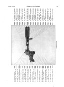
For example, part "1BCD3" is a part belonging to a Size No. 3 1/2 Barth (Machine Code "BCD"). It is a part in Group 1 (which will turn out to be the Frame of the machine). Often I'll refer to Groups both by their number and Machine Code; thus: 1BCD - Frame. Finally, 1BCD3 is the 3rd part in the Frame, which happens to be the right-hand side Standard.
So the parts list for the Size No. 3 1/2 Barth would begin:
(As an entirely arbitrary convention, I'll indicate left and right as they are seen from the operator's point of view (operator-left and operator-right). Port and starboard (that is, machine-left and machine-right) would have been more precise, but probably would have confused people.)
If I also find it useful in some particular situation to correlate a part symbol in this scheme with the numbering in a patent, I'll add the patent's number prefixed by "pat" (unless a different patent is clear by context, the default will be the basic Barth patent 376,765). So 1BCD5 is also (pat5), the Mold Block. (Only the first few part symbols correspond numerically to numbers on patent drawings; soon they diverge).
I'll use a set of machine codes which is consistent with the way in which I designate other machines I'm drawing/modeling at CircuitousRoot. (There's more about this in the CircuitousRoot Project Organization Notebook, but you needn't bother with it.)
For the Barths, I'll use a three character Machine Code. The first two characters are "BC" for "Barth Caster." The third character will designate the particular size (or other specifier) of machine. The Size No. 3 1/2 machine is: BCD.
For a while, I experimented with trying to do a logical system of codes in which the Size 1 machine was 'A', the Size 1 1/4 machine 'B', and so forth. But there are so many possible size Barths (from 1 to 4 1/2 in fractional sizes, plus wide-set variations), and we know so little about which machines were actually produced, that I soon ran out of alphabet while mostly designating machines which never existed (or which no longer exist, and are therefore basically undocumentable).
Instead, I've adopted an exceedingly crude method: I'll letter them as I go. The first three letters will be used for the three hypothetical machines described by the patents. These never really existed exactly as the patents said they did, but it will be useful to reconstruct them. Next comes the Size No. 3 1/2 Barth (which includes both the 60 point machine in my shop and, I think the 72 point machine in Greg Walters' shop). After that I'll see what comes up.
(I'm ignoring Barth's US patent 708,010 (1902) describing a vacuum mold.)
As to names for parts, we have imperfect guidance. Some names survive in the oral tradition handed down from ATF through Theo Rehak and the Dale Guild. When I know what this is, I'll follow it. For other parts, the patents provide a clue. Often, though, I'll just have to make something up.
There are also conflicts. For example, the flat table-like surface on which an operator might put his or her tools is called the "Table" in the patents. ATF/Rehak tradition calls it the "Apron" instead. But, confusingly, the patents use the term "Apron" to name the device which we would normally call the "Nipple Plate" (and which is called the Nipple Plate in the surviving ATF engineering drawing for it ).
To the extent that it is possible, I'll try to maintain parallel part symbols between machine sizes and identical names. So 1BCA3 and 1BCD3 will be the right Standard in both machines, and they'll be calle the "Standard, right" in both. These good intentions certainly will come to naught with the BCC machines (patents not by Barth & Lietze) as they describe a miscellany of potentially conflicting features.
All portions of this document not noted otherwise are Copyright © 2014, 2016, 2018 by David M. MacMillan.
Circuitous Root is a Registered Trademark of David M. MacMillan.
This work is licensed under the Creative Commons "Attribution - ShareAlike" license, version 4.0 International. See http://creativecommons.org/licenses/by-sa/4.0/ for its terms.
Presented originally by Circuitous Root®