This notebook illustrates one procedure for removing the levers at the front of the Lanston [i.e., American] Monotype-Thompson Type-Caster. It may or may not apply to the English Thompson, or to early Thompson Type Machine Company machines. There may also be differences between individual American Thompsons.
Unless otherwise indicated, the part numbers called out are those from the 1956 Monotype Thompson Adjustments manual (Philadelphia: Lanston Monotype Machine Company, 1956) together with the 1941/1942 Monotype-Thompson Type-Caster Parts Price List. (Philadelphia: Lanston Monotype Machine Company, 1941-03-01 (revised 1942-04-02)). Both of these are available in the ../../../ Thompson Type-Caster Source Material (An Anthology).
The following tools will be necessary (or at least handy):
1. A wooden dowel preferably of about the same diameter as (but no greater diameter than) the Cam-Lever Shaft (5TC1; the shaft on which the Levers pivot). As will be seen, it is convenient if this dowel is the same diameter as the shaft, but it need not be. All that is strictly required is a soft punch of suitable material (wood, nylon, etc) to drive the shaft out without damage. On my American Thompson s/n 13,068, this shaft is 7/8 inches in diameter (to within 0.001, actually). This dowel or soft punch may conveniently be 8 to 12 inches long.
2. A medium-weight hammer. A machinist's ball peen hammer is ideal.
3. A medium-sized flat-blade screwdriver (for loosening "Mold Stand Set-Screw (Headless) (for 5TC1)", 54TC39).
4. Ideally, a larger-bladed, relatively long flat-blade screwdriver (for removing the Pump Stop group, 77TC).
5. Long-nosed pliers for removing Pump-Cam Lever Rod Cotter (76TC3). Improvised tools as required for getting old cotter pins out of tight spots.
6. Optionally (if the procedure is undertaken with the pot hot) a shop-made L-shaped diverter tube, not a standard Monotype part, to be placed over the nozzle of the pot (when swung back) to divert any metal from the nozzle downward. This nonstandard safety device may be fabricated out of a copper plumbing elbow of suitable diameter.
7. A clear space of about two square feet on the workbench, covered with a clean shop rag or paper towels, for receiving the Levers removed from the machine. It's easier to clear this before you have the first Lever in your hand.
A new 1" nominal length steel cotter pin probably will be required if the Pump-Cam Lever is removed.
The procedure described was performed on a machine in operating condition. If the machine is already in a partial state of disassembly, you're on your own.
The machine's electrical power switch should be turned off. Further, the machine should be unplugged or its circuit breaker set to OFF. You will have your fingers inside the machine, and really do not want it turning on because you accidentally bumped a switch.
If it is cold, the pot may be either locked up or swung back at the start of the procedure; it will be swung back later in the procedure.
If the Pot is hot it must be swung back at the beginning of the procedure so as to ensure that the Pump and Choker Valve cannot operate. This is important, since in this procedure both the Matrix Carrier and the Pump Stop will be removed. If a casting stroke should accidentally occur with the Pot engaged and the Matrix Carrier removed, extremely serious injury could result from the resultant high-pressure jet of molten typemetal out the front of the machine. Remember that the Thompson's casting stroke is powered by spring pressure, not the motor. The machine can perform a casting stroke even with the motor disconnected.
When the pot is swung back, a suitable L-shaped diverter tube (not a standard Monotype part) should be placed over the nozzle so as to deflect any metal from the nozzle downward.
The machine should be stopped in the "12 o'clock" position simply because the machine should always be stopped in a consistent position when not engaged in casting.
Since this is a maintenance procedure, during the procedure the Matrix Carrier (group 26TC) may (and will) be removed from the machine and set down on the bench. A rigorously enforced (and very intelligent) operating rule at Skyline Type Foundry (the place of my apprenticeship on the Thompson) is that when casting the Matrix Carrier may be in one of only two places: (1) in the casterman's hand or (2) in the machine, with a matrix in it, locked up for casting. You may never put it down and remove your hand from it, because sooner or later you'll forget that you did this and attempt to operate the caster without it in place. (I do, in fact, know of one instance, not at Skyline, where a friend who had not been taught this operating procedure did engage the machine having forgotten to return the Matrix Carrier to it. Fortunately, no harm occurred, but this could have resulted in a very serious injury.) This present operation is a maintenance operation, so it is permissible to set the Matrix Carrier on the bench. It is up to the operator to have in place an adequate start-up procedure which will ensure that the Matrix Carrier, with a matrix in it, is returned to the machine and locked up before casting resumes.
The Pump-Cam Lever (group 76TC) is under tension from the Piston-Spring.
If the Pump-Cam Lever itself is not to be removed, and if a dowel the diameter of the Cam-Lever Shaft is used, then it is possible to remove other levers without releasing the tension on the Pump-Cam Lever (although work will generally be easier if this tension is released). If the Pump-Cam Lever is to be removed, then the tension on it should be released as the first step in this procedure.
This is done by releasing and rotating the Piston-Spring Tension Pulley Shaft Ratchet (with handle), 74TC6, located at the bottom rear of the machine. Before doing this it is a good idea to find some way of getting the old setting back, either by marking it on the ratchet or by recording the number of ratchet steps released. Failure to do this will mean that the tension, and consequently the Pump pressure, will have to be redetermined when casting resumes.
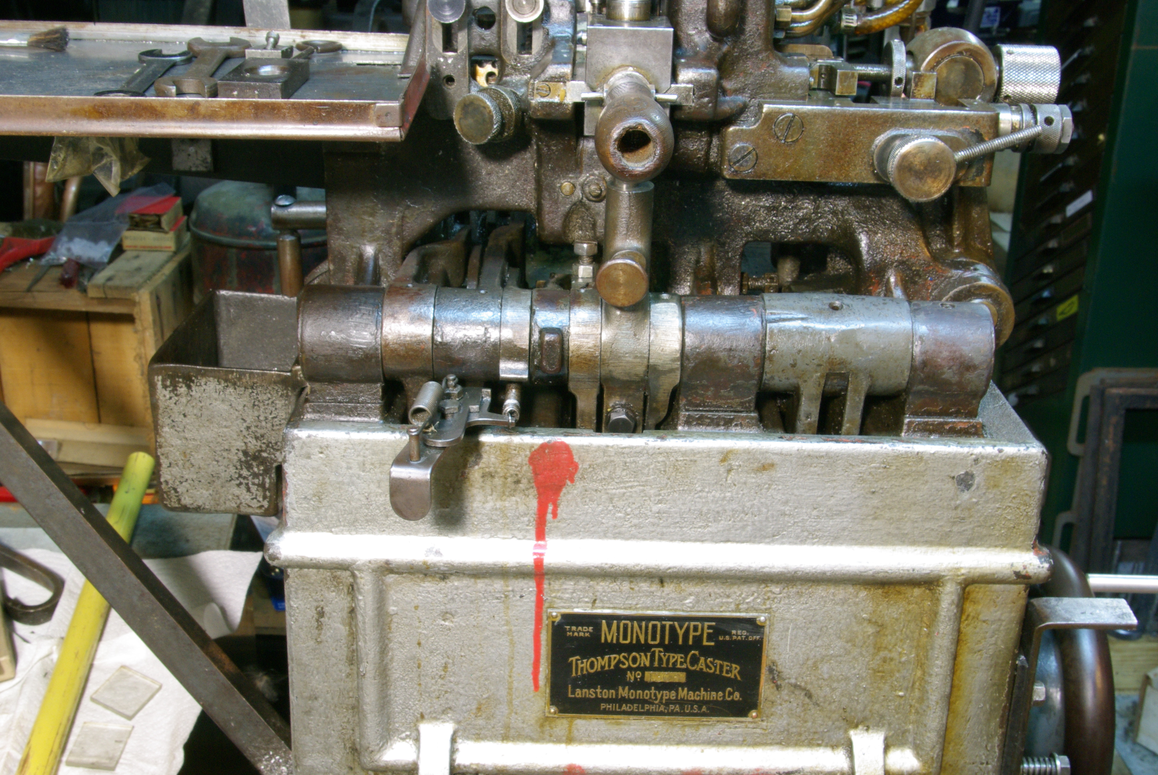
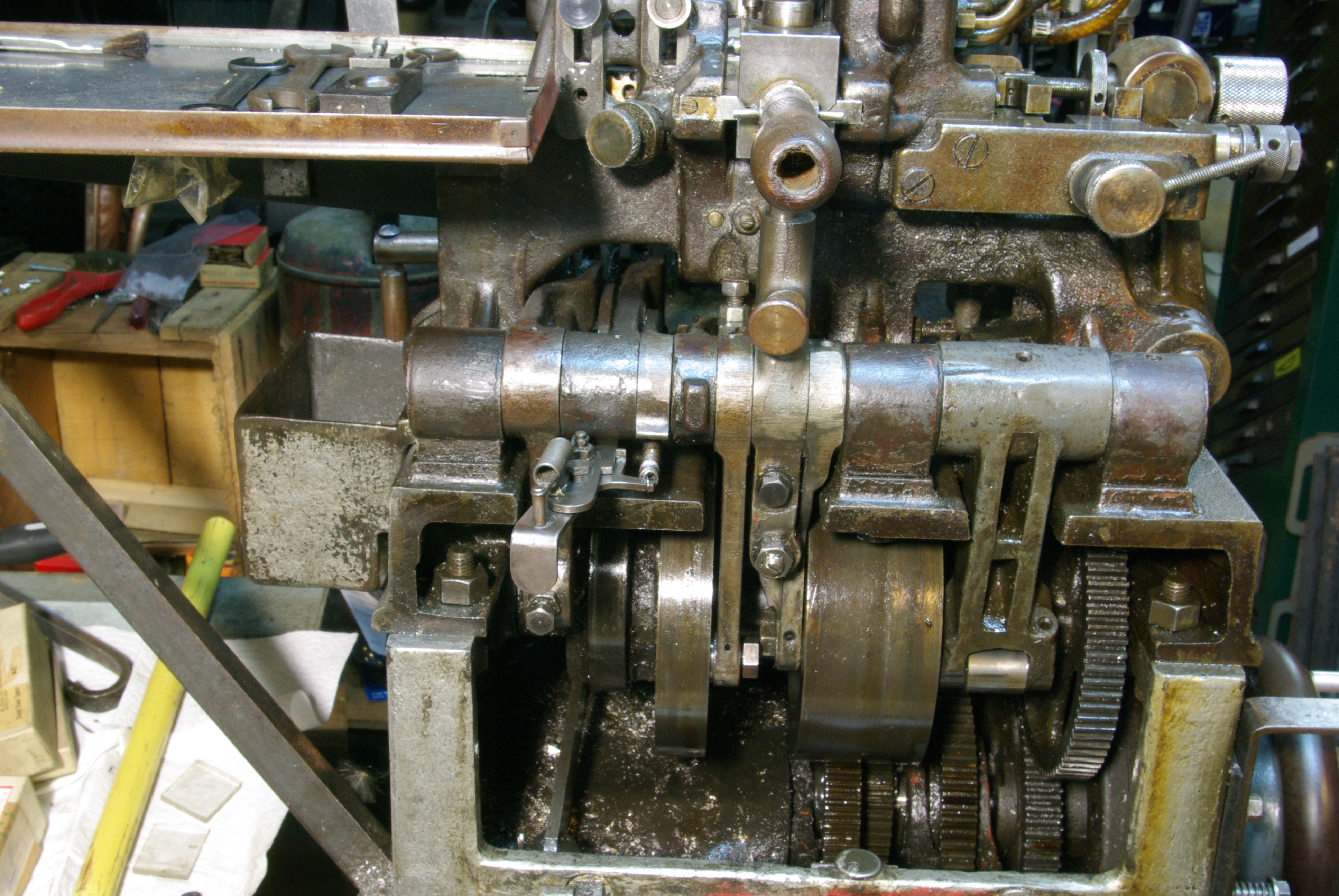
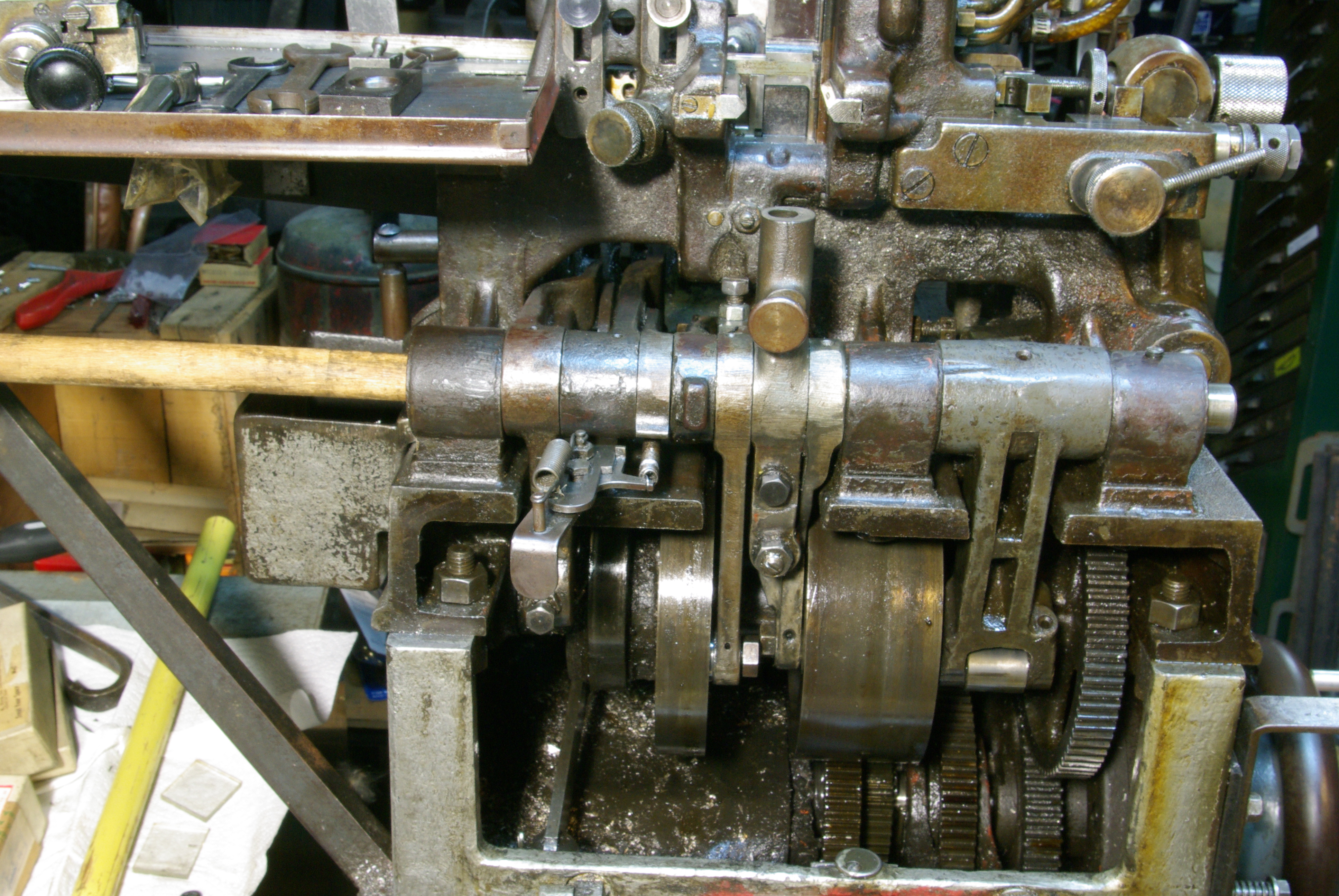
Here's the machine. Ignore the monstrous galley-based "delivery stick" on the left, and the blotch of red paint. This machine has had a hard life, but things are looking up for it now.
IMPORTANT: if the Pot is hot, then before removing the Matrix Carrier for a maintenance operation such as this one ensure that the Pot has been swung back out of engagement, as described earlier. If this is not done, then the machine will be left in a state where a casting stroke, should it accidentally occur, would deliver a jet of molten typemetal out the front of the machine.
Remove the Matrix Carrier. Obviously, the red circle in the image below marks the place where it is no longer.
Also remove the Matrix-Carrier-Cam Lever Extension Fork (30TC3T); this will lessen the chance of it falling out when this Lever is removed.
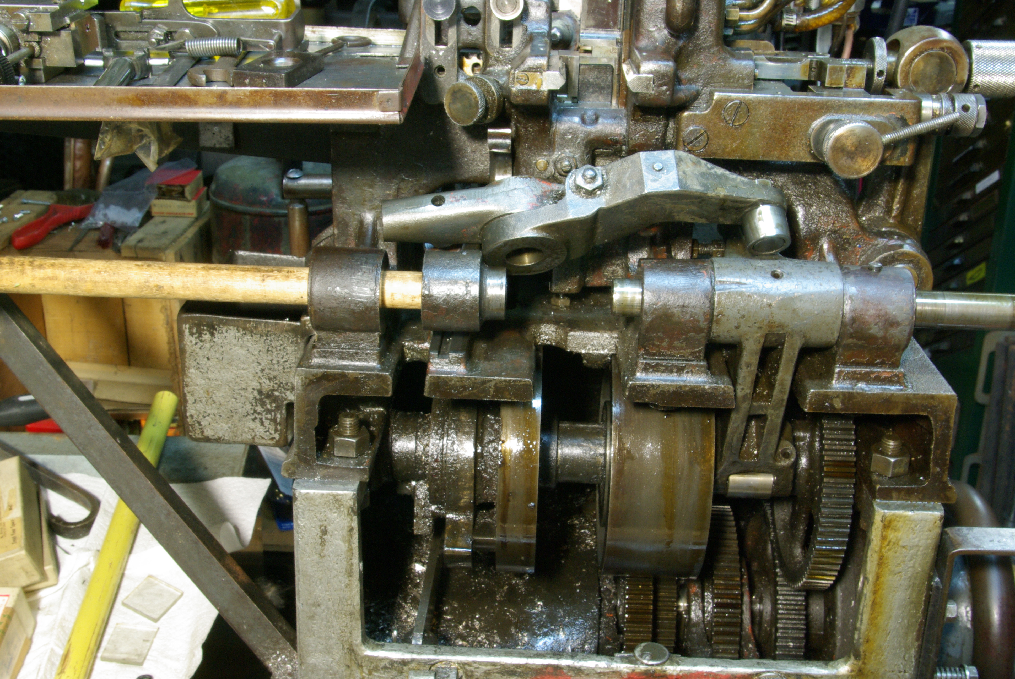
All of the Levers at the front of the machine pivot on a single shaft, the Cam-Lever Shaft (5TC1). This Shaft is fixed; it does not turn. It is held in three plain holes in the left and right parts of the Mold Stand. (These are outlined in blue rectangular boxes in the image below.) It has an annular ring turned into its right-hand side, and is fixed longitudinally by a set screw, "Mold Stand Set-Screw (Headless) (for 5TC1)", 54TC39). This set screw is at the right of the shaft.
Loosen this set screw. It doesn't need to be removed completely.
The 1950 and 1956 Monotype-Thompson manuals indicate one set screw only, on the right of the Shaft. However, I have seen one machine in which a second set screw had been installed on the left of the Shaft. Also, the 1925 Thompson Type Machine Company manual shows a Shaft (K-585, Plate 15) with two annular rings and calls out two parts X-114-4, "Set Screws for Cam Lever Shaft." But the illustration of the Shaft in the 1925 manual shows both annular rings on the same side of the shaft while the illustration of the Mold Stand (N-502 and N-503 on Plate 17) shows one set screw hole on the far left and another on the far right. So if you have never removed the Shaft before, check all three of the points where the Shaft passes through the Mold Stand for one or more set screws. Bear in mind that they may be hidden under grease or typemetal and may not be obvious.
The Shaft may be driven out in either direction, left or right. In the procedure shown here I drive it out from the left to the right because in my own experience I have had to deal more often with the removal of Levers on the left. However, if the only Lever to be removed is the Mold Body Cam Lever group, 49TC, then it would make more sense to drive the shaft out right-to-left.
Here are the tools for driving the Shaft.

Start driving the Shaft out. Take this slowly, and start carefully. The Shaft is a precision sliding fit in its holes. It should come out with gentle taps; if you have to really hammer on it, something is wrong.
Do not just drive the Shaft completely out. We're going to take the Levers off one at a time, and for now only want to drive it far enough to remove the first Lever.
It may be obvious, but you can judge how far you've gone by either (a) taking the dowel out and using it as a measuring stick, or (b) looking at how much shaft is now sticking out on the other side.

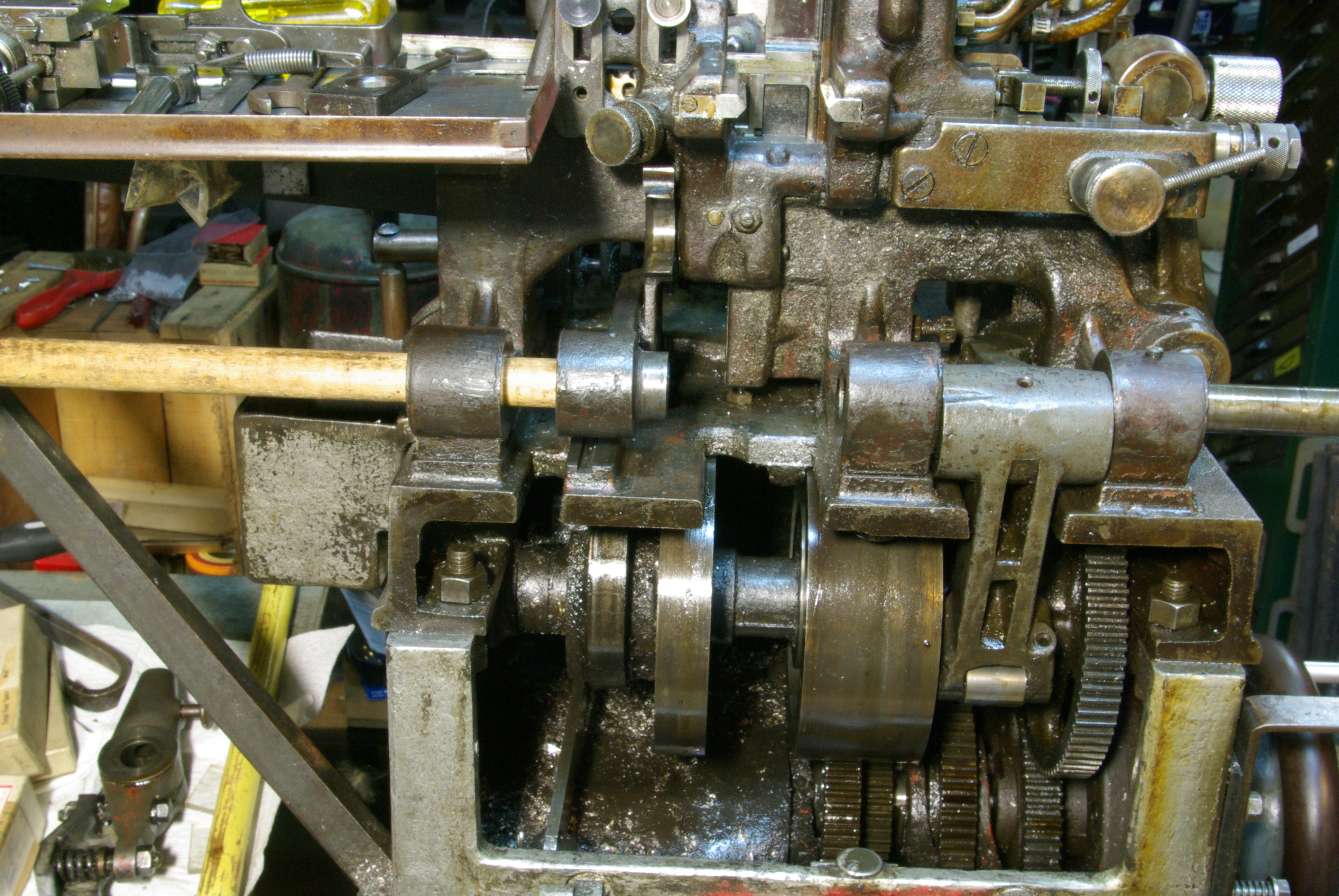
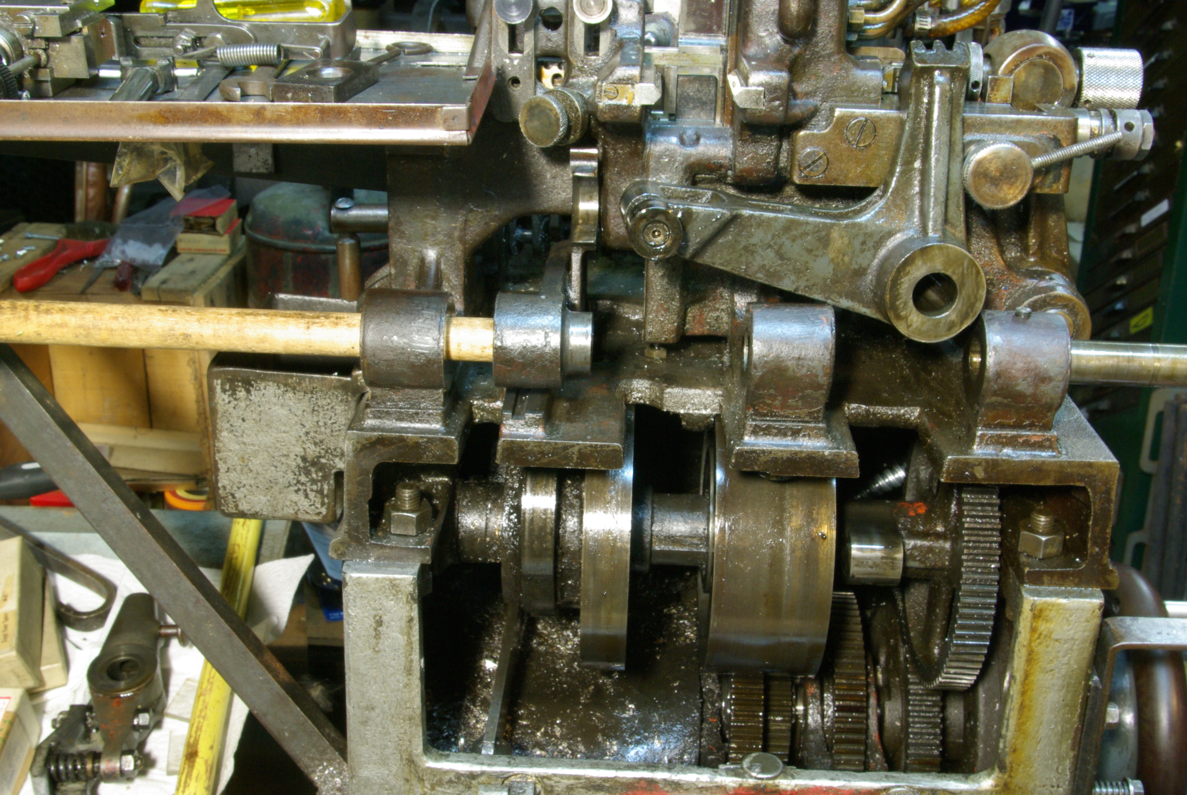
Drive the Shaft just far enough so that it is past the leftmost Lever, which is the Choker-Cam Lever (group 6TC).
This Lever is the easiest to remove. It simply pivots on the Shaft, so when the Shaft is removed there is nothing holding it in. None of its cam followers are constrained by the cams (whereas many of the other Levers have followers which run in grooves). When you punch the Shaft clear of this Lever and remove the dowel/punch, there is nothing at all holding this Lever in the machine. Usually it will stay in place, held in by oil and its close fit, but it could just drop out onto the floor. As you pull the dowel leftward to remove this Lever, therefore, hold the Lever so that this cannot happen.
The photo below shows this Lever removed. You should remove it and place it immediately on the bench on a clean shop rag or paper towel
(In the photo below, and similarly in several photos to come, I've perched the Lever precariously on the machine so as to be able to get a picture of it without moving my camera. I would advise against doing anything like this. I was (a) being very careful, but (b) being lazy in photography.)

The next item to be removed is not a Lever, but rather the Pump Stop assembly.
IMPORTANT: If the pot is hot, then it must be swung back out of engagement with the Pump-Cam Lever before the Pump Stop is removed. This ensures that a casting stroke can never accidentally occur with the Pump Stop removed from the machine. (This present note should be redundant, since if the pot is hot it should have been swung back out of engagement before the start of this entire procedure (and certainly before the Matrix Carrier was removed.))
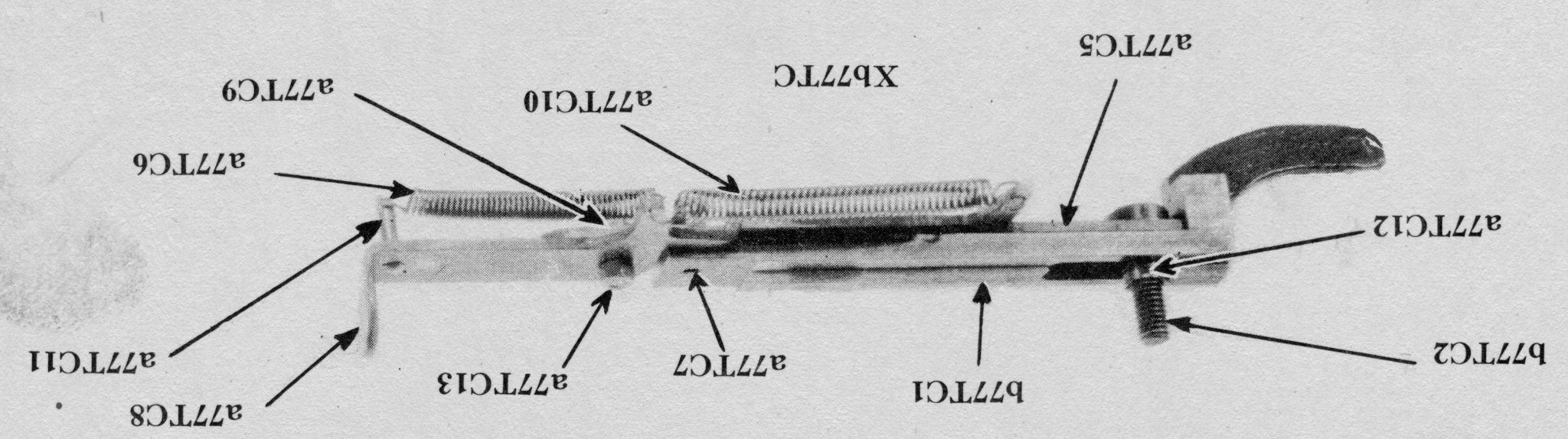
Note: The form of the Pump Stop shown here, Xb77TC, is the latching form applied to machines s/n 11,760 and later, and sometimes refitted to earlier machines. The Monotype-Thompson documentation indicates at least two earlier styles of Pump Stop. Thompson Type Machine Company machines were supplied with a style of Pump Stop quite different from the one shown here (see for example P-682 on Plate 15 of the 1925 Thompson Type Machine Company manual).
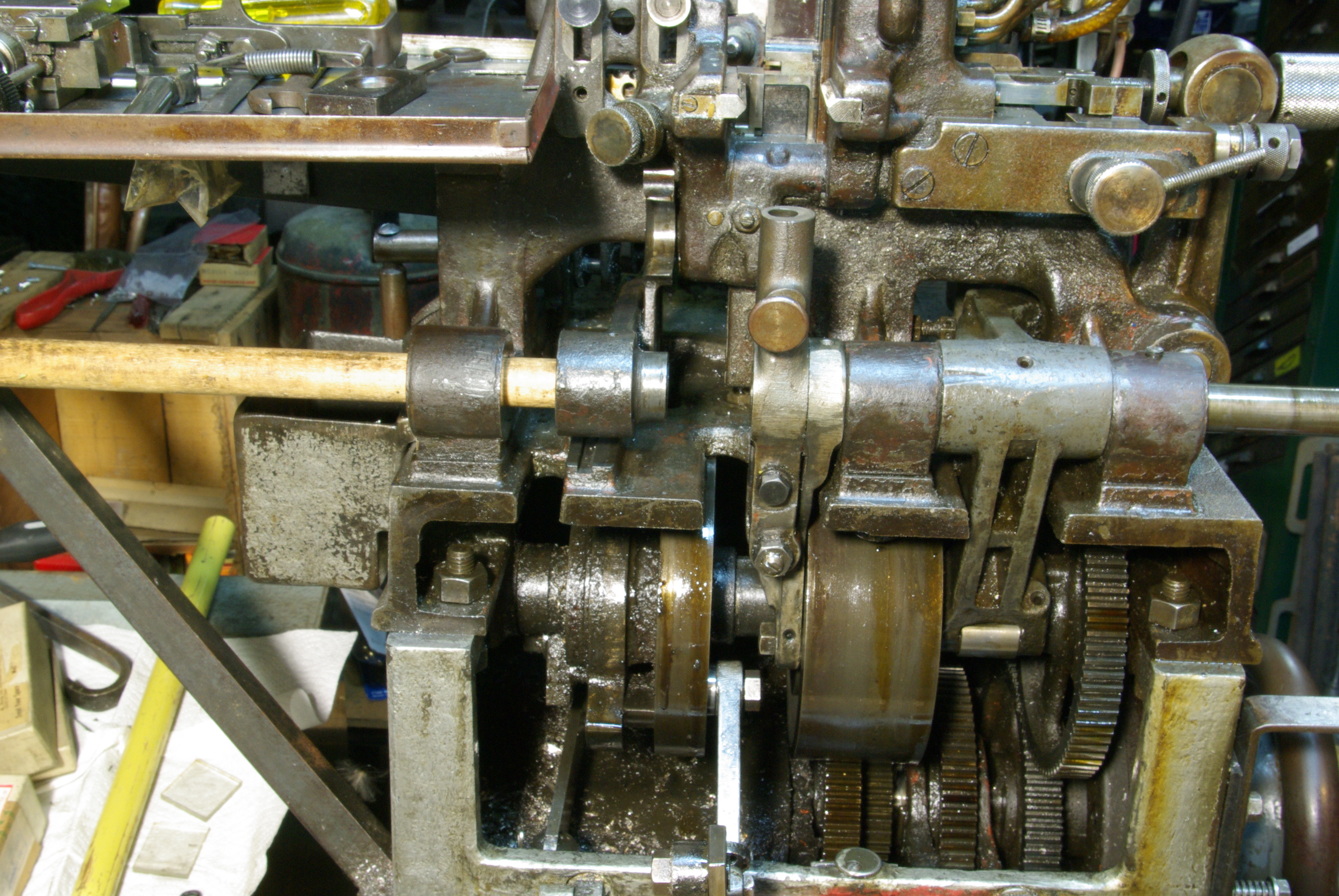
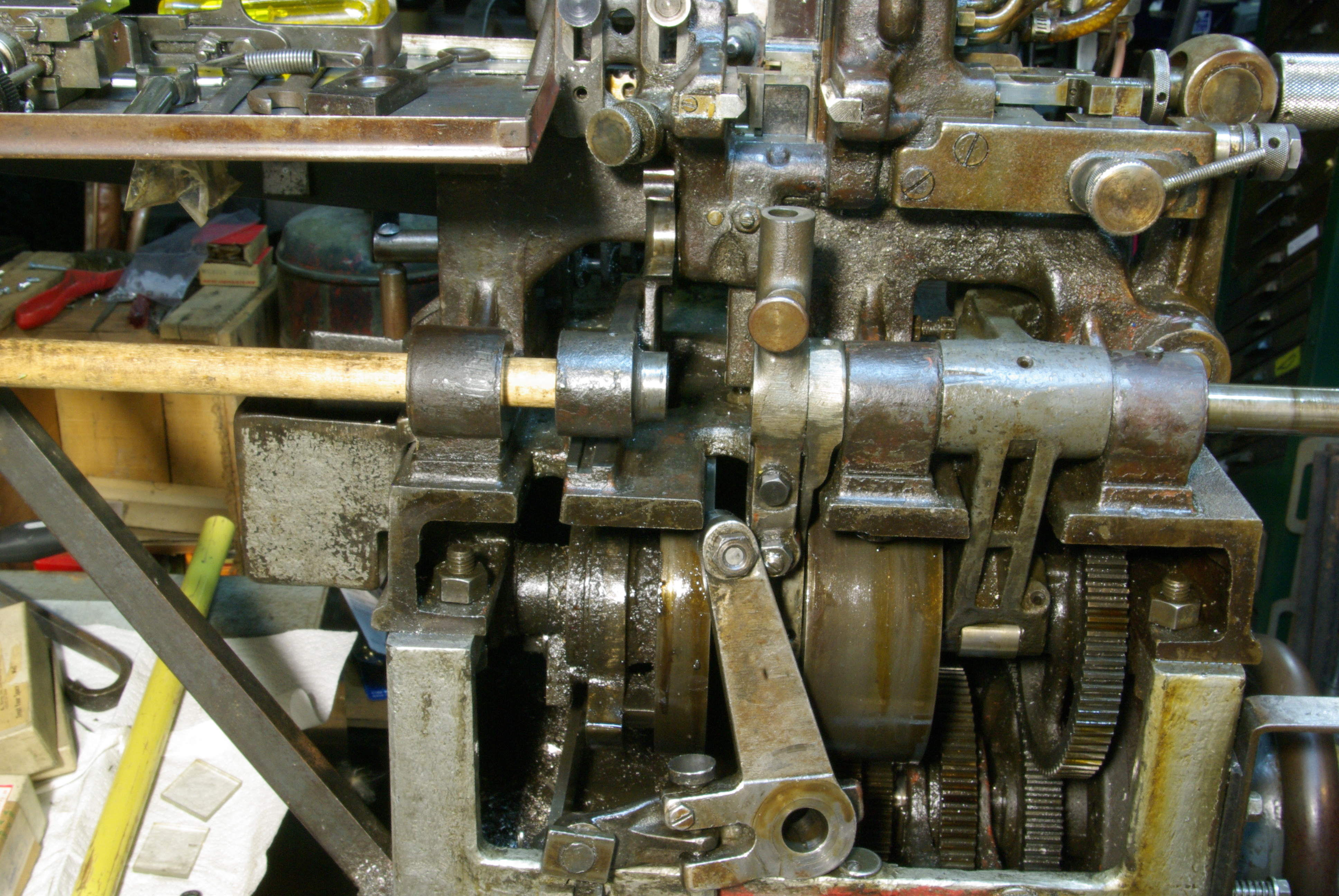
The Pump Stop has two positions.
In its Engaged position, where it is in fact stopping the Pump, the Latch (a77TC8) is knocked to the left, allowing the Pump Stop Plate (a77TC5) to slide in and under the Pump-Cam Lever (a76TC1T). In this position, the Pump-Cam Lever cannot drop, and a casting stroke cannot occur.
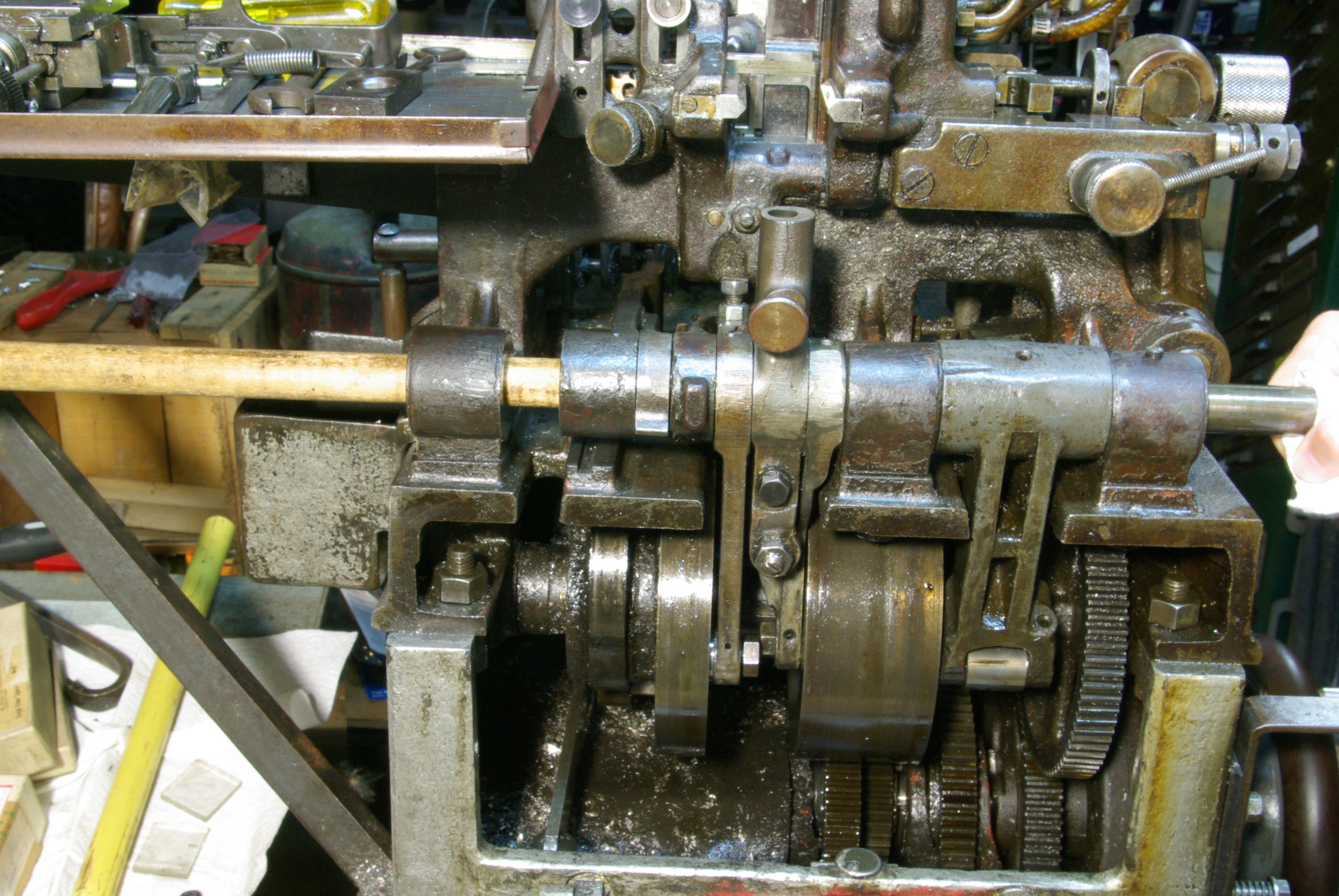
The photo below shows the Pump Stop in its Engaged position, blocking a casting stroke. Note that the Latch (circled in red) has been knocked to the left.
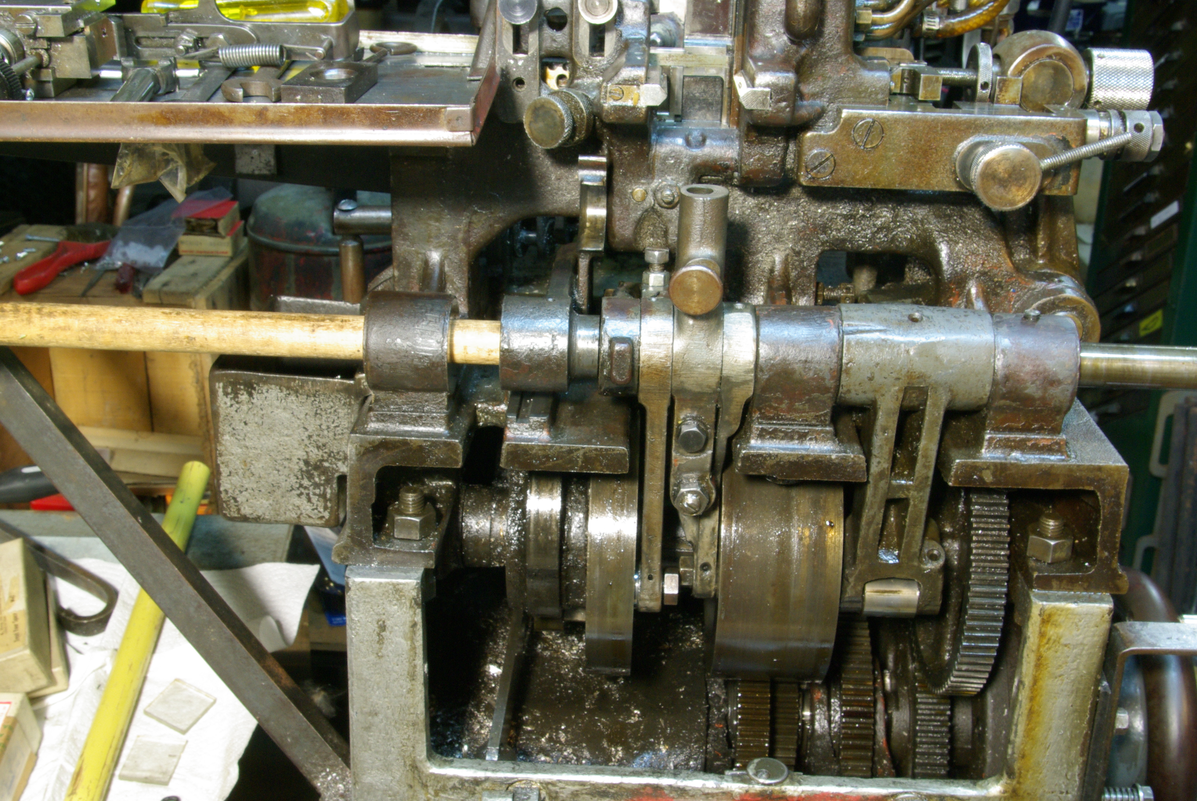
In its Disengaged position, where it is not stopping the Pump, the Latch is pulled out toward the operator. This pulls the Pump Stop Plate outward so that it no longer blocks the Pump-Cam Lever. A casting stroke may occur.
The photo below shows the Pump Stop in its Disengaged position, permitting a casting stroke. Note that the Latch (circled in red) has been pulled out.
If the tension has been released on the Piston-Spring, as described earlier, then the Pump Stop should be under no significant pressure in either of its two positions. It may be removed in either position, but it's probably easiest to remove it in the Engaged position (because the Latch is at its "lowest energy" state and can't snap shut on you accidentally as you remove the unit from the machien).
If the tension has not been released on the Piston-Spring, then the Pump Stop will be under pressure in its Engaged position and must be Disengaged before removal.
Rigging Note: When moving a Thompson Type-Caster, it is a good rigging practice to remove the Pump Stop. It is a piece of relatively thin metal sticking out the side of the machine; it's just asking to be bent during rigging. Remove it, put it in a zip-sealing plastic bag, and keep it somewhere closely associated with the machine it came from. If doing this with multiple Thompsons, clearly identify the Pump Stop so that it may be returned to the machine from whence it came. (Pump Stops were commonly filed down to compensate for wear in the Pump-Cam Lever, and should be considered as items fitted to a particular machine.)
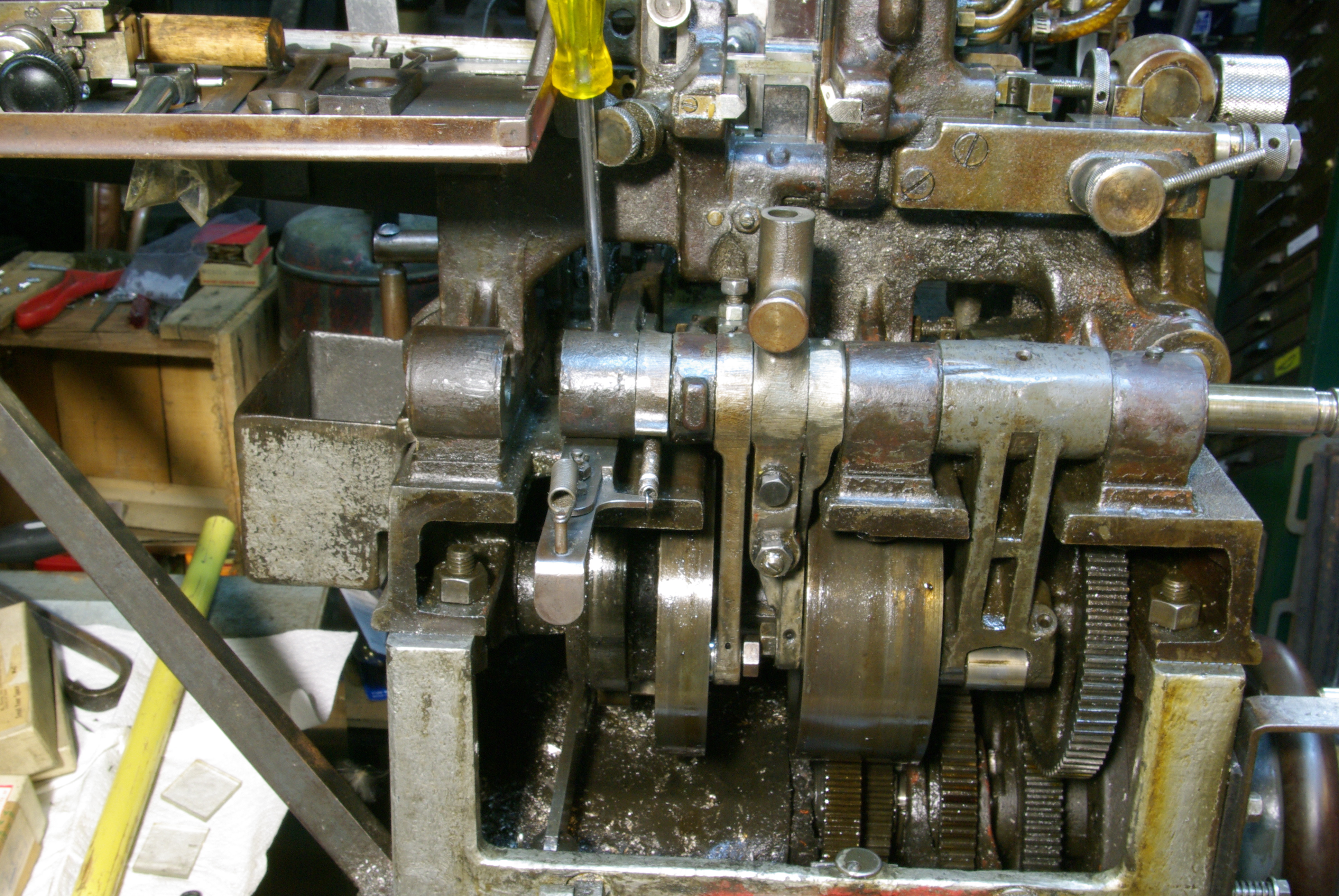
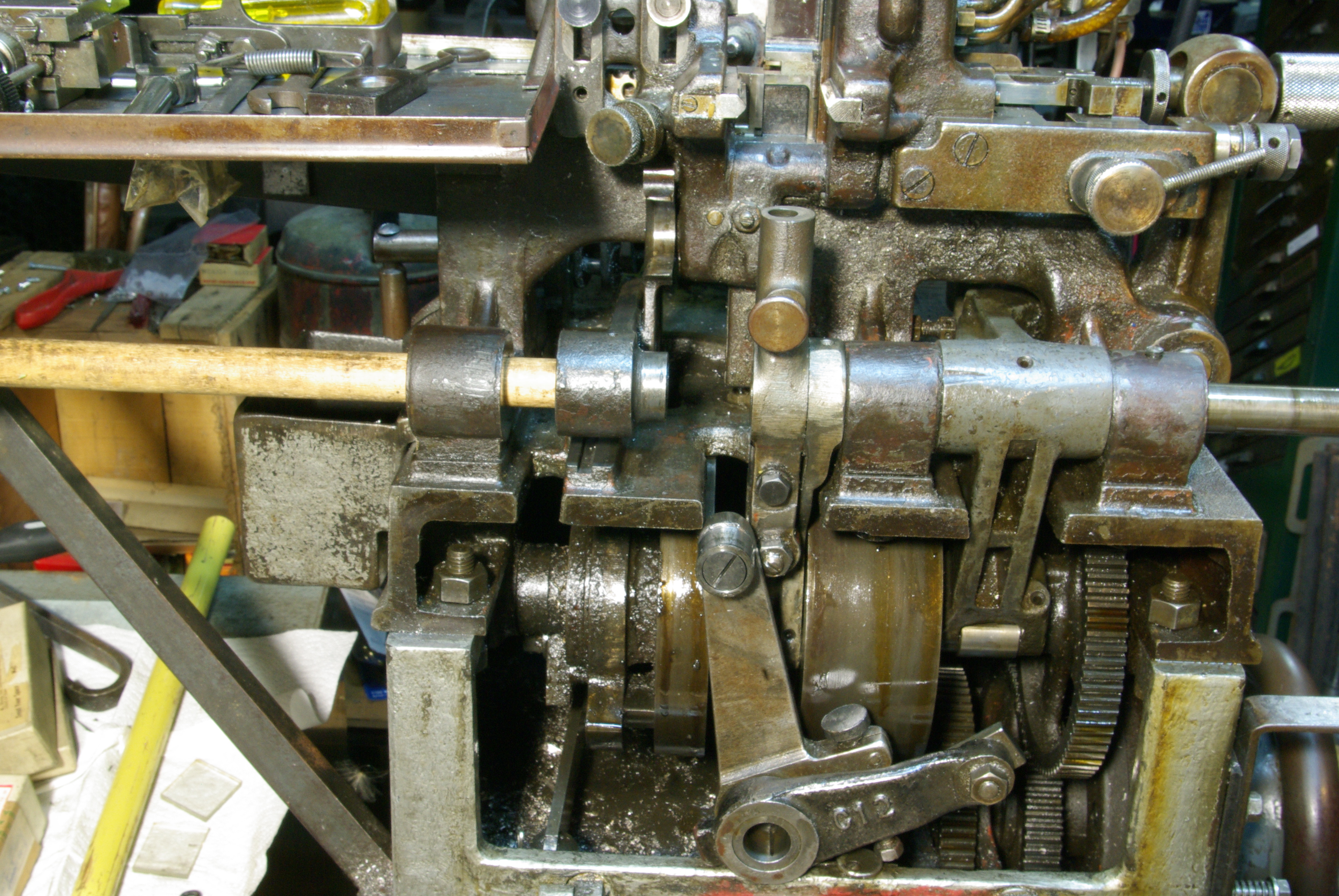
To remove the Pump Stop, first remove the Pump Stop Plate Screw, b77TC2. The photograph above shows a yellow-handled screwdriver being used to remove this screw. The photograph below shows it, removed from the machine.
The only issue in removing this screw is that it is designed for a wide-bladed screwdriver. Yet there is no straight path down to the screw; you must use the screwdriver at an angle. Doing so is easier with a narrow-bladed screwdriver, both because it is easier to rotate a narrow-bladed screwdriver at an angle while keeping it engaged, and because the shaft of a narrow-bladed screwdriver tends to be thinner. However, if the screw is tight then using a narrow-bladed screwdriver risks bending the blade and/or marring the slot. It is good to work carefully and useful to have a wide selection of screwdrivers.
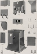
In my Thompson, this screw is a simple cheese-head shoulder screw which acts as a stud. In the Monotype-Thompson documentation, there is an additional part on this screw, a77TC12, Pump Stop Plate Screw Collar. I do not know if my machine is simply missing this Collar and ought to have it or if the form of the Screw on my machine differs from that illustrated in the manual. Here's the assembly from the 1956 Lanston Monotype Thompson manual, rotated so that the Pump Stop is shown right-side-up:
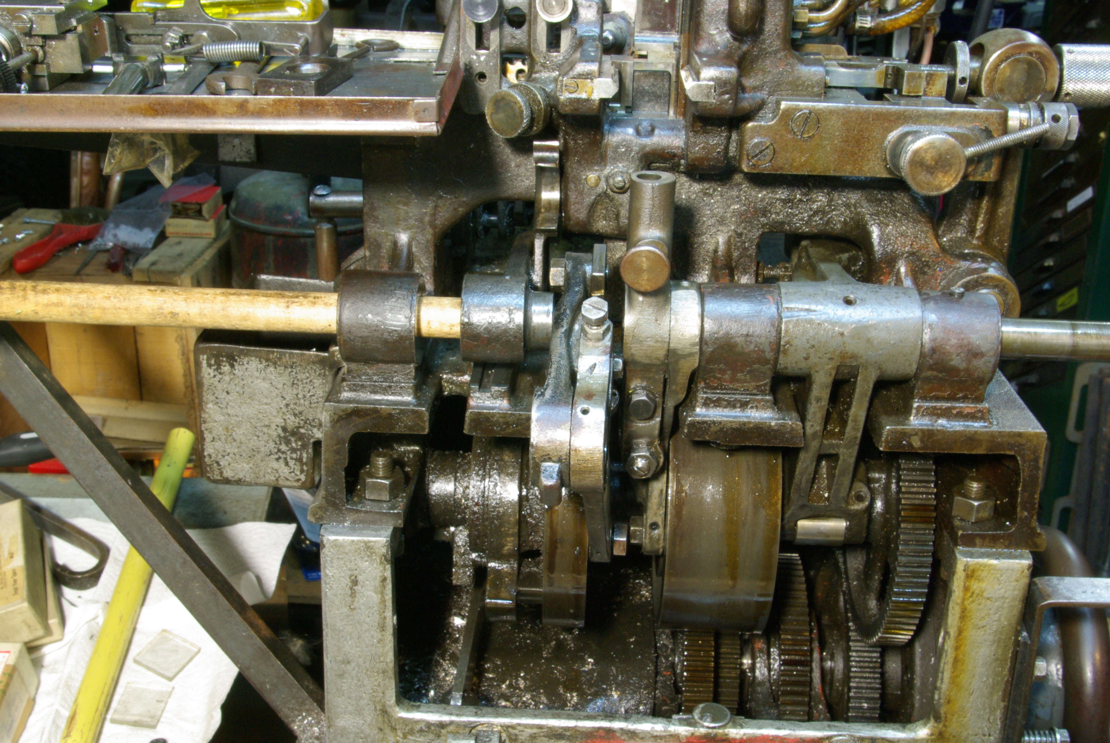
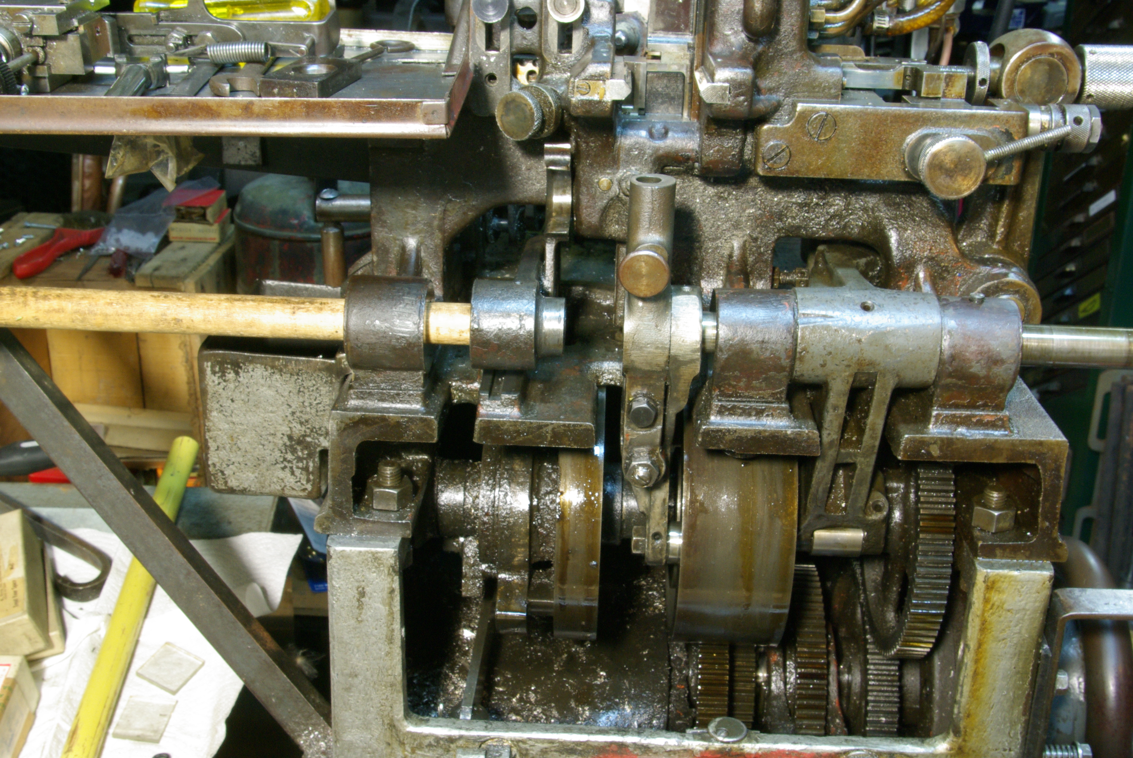
After the screw is removed, wiggle the Pump Stop assembly out. It has a ridge along its bottom side which fits snugly in a slot on the machine. There should be just enough vertical clearance under the Pump-Cam Lever to remove it. The photo below shows the Pump Stop assembly (outlined in a blue box) removed and resting on the machine. The Pump Stop Plate Screw is circled in green. The slot in which the Pump Stop Plate fits is circled in red.

From this point on, it is likely that it will no longer be necessary actually to drive the shaft with the dowel and hammer. On my machine, at least, it slides easily enough that it may simply be grasped on the right-hand side and pulled.
Depending on which Levers are to be removed, however, the dowel still may be useful. There is a mechanic's trick of general utility which may be used here: If you have a number of items on a single shaft and you wish to remove only one in the middle, use another shaft (the dowel, here) to drive the primary shaft over to the point where the removal is to occur. Then separate the two just enough to remove the one piece. This procedure keeps all of the parts on some shaft, in order. (It is very handy when working on Linotye escapements, too.)
In the procedure described here I'm actually going to skip the next Lever, the Pump-Cam Lever, and go on to the Matrix-Carrier-Cam Lever. As it happens, the Pump-Cam Lever isn't just going to fall out of the machine, so it isn't strictly necessary to secure it with the dowel; I find it convenient to do so, though.
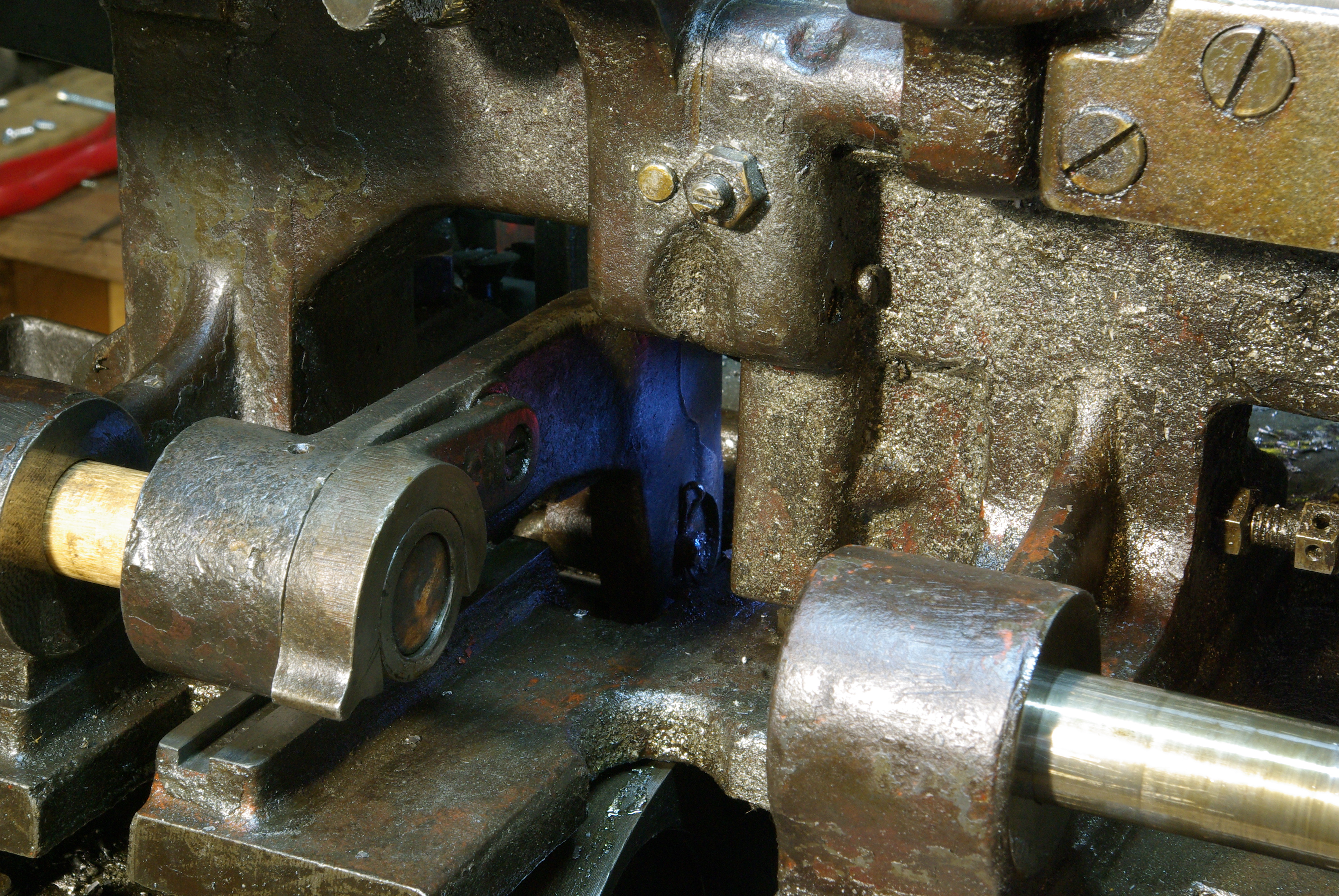
Before continuing, a word about the Pump-Cam Lever Yoke, a76TC10, may be in order.
The function of this part is simply to act as a spacer when in its "down" position (shown below, boxed in red). It keeps the Vertical-Mold-Blade Lever (52TC, which forms an assembly with the Vertical-Mold-blade-Cam Lever 53TC) from shifting leftward on the Shaft.

The Vertical-Mold-Blade Lever (52TC) is designed with a larger (than the Shaft) hole through it so that when the Pump-Cam Lever Yoke is moved to its "up" position the VMB Lever can slide to the left, over the now exposed portion of the Pump-Cam Lever. This allows the VMB lever to be disengaged from the Vertical Mold Blade itself.
If the next Lever you choose to remove will be the Pum-Cam Lever, then you may ignore this Yoke. It will be removed as a part of the Pump-Cam Lever assembly.
(N.B., removing the Yoke does not, so far as I can tell, make it any easier to remove the Pump-Cam Lever. I just tried it.)
If, as I do here, you will skip the Pump-Cam Lever for now then you will have to move this Yoke to its "up" position in order to remove the Vertical-Mold-Blade-Cam Lever / Vertical-Mold-Blade Lever assembly.
If you were simply removing all of the Levers, then the next one to remove would be the Pump-Cam Lever.
The Pump-Cam Lever, however, is the most difficult of all to remove. Moreover, it is frequently the case that one wishes only to remove the Levers involved with the Vertical Mold Blade and the Matrix Carrier. When doing this, it is easiest to leave the Pump-Cam Lever in place.
So in the procedure here I'll skip the Pump-Cam Lever at present and remove it later.
The next Lever in this procedure is therefore the assembly of two levers which control the Vertical Mold Blade. This assembly is removed as a unit. The two levers in this assembly are: (1) The Vertical-Mold-Blade-Cam Lever (group 53TC); this is the Lever which goes from the Shaft down to the Cam below. (2) The Vertical-Mold-Blade Lever (group 52TC); this is the lever which goes from the Shaft back to the bottom of the Vertical Mold Blade.
The Vertical-Mold-Blade Lever engages the Vertical Mold Blade using a rectangular block, the Vertical-Mold-Blade Lever Lifting Block (52TC2). This block is a close fit in the corresponding rectangular recess at the bottom of the Vertical Mold Blade. Once the Lever is removed, this Block spins freely on its Stud (52TC3). This means that when replaced it may go in one of two orientations, 180 degrees apart. To the best of my knowledge, it does not matter which orientation it is in. However, if there is a difference between them then this would affect the position during the machine cycle of the Vertical Mold Blade. If the VMB is not positioned very accurately, severe damage to the machine may result.
It is therefore a very good idea, before removing this Lever assembly, to familiarize oneself with the procedures for the adjustment of the Vertical Mold Blade. In the 1956 revision of the manual this procedure starts on p. 41. If the Vertical Mold Blade is not correctly adjusted, then during the mahine's cycle it might be struck by the Type Body Piece, resulting in serious damage to the machine and to scarce precision parts.
This adjustment procedure is well documented there, with one exception. The manual fails to note that the adjustment of the machine will change with temperature. If the procedure described in the manual is followed with the machine cold then when the machine is operated at temperature the Vertical Mold Blade, having expanded, will be just a few thousandths of an inch too high and will be struck by the Type Body Piece. It is best to make this adjustment with the machine near operating temperature. It is always necessary to cycle the machine carefully by hand before operating it under power.
[NOTE TO SELF: do a series of better photographs of this.]
To remove the VMB Lever assembly:
(1) Flip the Pump-Cam Lever Yoke to its "up" position.
(2) Rotate the main shaft of the machine backwards (towards you; counterclockwise were you to view the Hand Wheel (10TC13T) face-on.) The reason for this is that it moves the Vertical Mold Blade Cam to a position where there is more room in the Cam itself to wiggle the Lever assembly free. This 90 degree rotation is not shown well in the photographs here, but has been done.
(3) Move the dowel to the right so as to support the Pump-Cam Lever (only), stopping before the VMB Lever assembly.
(4) Move the Shaft (by hand) to the right so as to clear the VMB Lever assembly but still support the next Lever (the Matrix Carrier Lever assembly).
(5) Wiggle the Lever assembly leftward so as to disengage the Vertical-Mold-Blade Lever Lifting Block from the Vertical Mold Blade.
(6) Raise the Vertical Mold blade by hand so that you can slide the VMB Lever assembly back to its normal position.
(7) Move the VMB Lever assembly forward out of the machine. It will be pivoting on its cam follower, still in the Cam. Make sure the Vertical Mold Blade doesn't just drop down.
In the photo below, these steps have been done. The VMB Lever assembly is outlined in a blue box. The Vertical Mold Blade Lever Lifting Block is circled in red.
(8) Rotate the VMB Lever assembly forward and slide its cam roll out of the Cam. In the photo below, the VMB Lever assembly has been swung forward and is shown hanging precariously from its cam roll. In the two photos after that, it's balanced on the front of the machine. Neither of these things is of course not to be recommended (I just did them for the photograph); remove the VMB Lever assembly entirely in one motion, holding on to it :-) Put the VMB Lever assembly on the bench on a clean shop rag or paper towel.
The Matrix-Carrier-Cam Lever (group 30TC) is a single Lever in two parts, pivoted and spring-loaded in the middle. It can be treated as a single assembly for removal.
By this time, removing it is quite simple: just slide it to the left, off the Shaft. Its cam roll will disengage easily from its Cam.
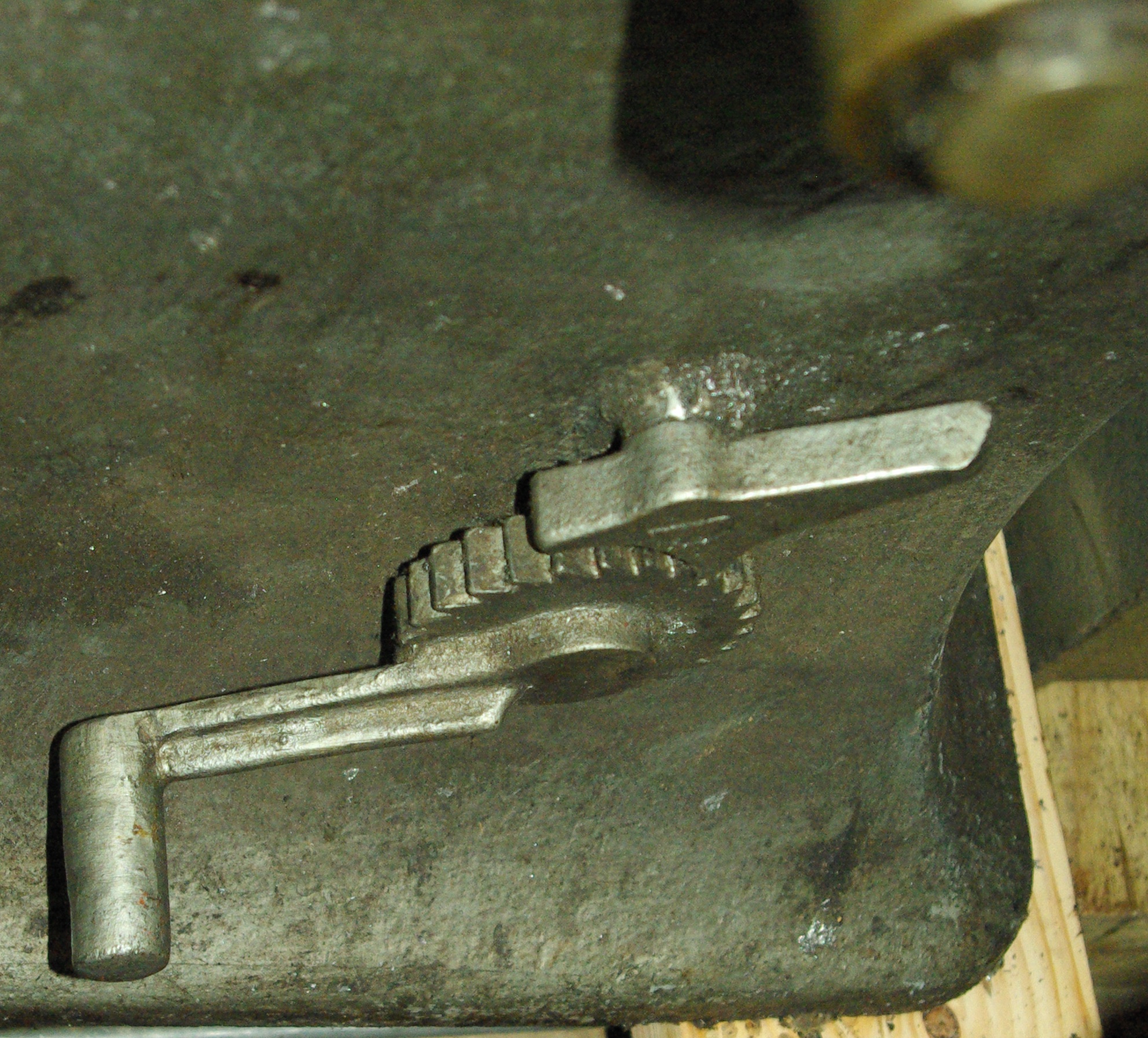
The rightmost Lever to be removed in this procedure is the Mold-Body-Cam Lever. While it is quite easy to remove, it has two features worthy of note.
It is the first in a two-part series of levers which control the horizontal motion of the Type Body Piece in the Mold. The Mold-Body-Cam Lever (group 49TC) transfers its motion to the Mold-Body Lever (group 48TC) with a 90 degree shift of plane via sectors of a bevel gear. This is an unusual motion not found elsewhere on the machine.
The Mold-Body-Cam Lever also has a more complex set of cam rolls. These consist of two rolls: the Mold-Body-Cam Lever Roller (center), 49TC2, and the Mold-Body-Cam Lever Roller (side), 49TC3. These two cam rolls engage different Cams to provide the motion of this Lever.
It is useful to study the way in which these cams, followers, levers, and sectors operate, because the motion they transmit, the horizontal motion of the Type Body Piece in the mold, is one of the most frequently changed settings on the machine. Note that there are no springs or mechanisms for "give" anywhere in this path (other than lost motion due to play in the parts); the path is in theory rigid. It is good to remember this when adjusting the Micrometer Set-Adjusting Device, where this theoretically rigid motion is brought up against an absolutely rigid stop.
To remove the Mold-Body-Cam Lever, return the Hand Wheel to the 12 o'clock position (it's easier to get the Lever's cam roll out with its Cam in this position). Then pull the Shaft to the right past the Lever. Keep a hand on the Lever to make sure it doesn't just fall out and onto the floor.

At this point, the Shaft is sticking well out at the right of the machine. Either remove it entirely and put it someplace safe and clean, or slide it back to the left as appropriate.

Last in this procedure comes the Pump-Cam Lever (group 76TC). It is the most difficult of the Levers to remove, and unless it is necessary to remove it, I wouldn't.
First, swing the Pot back entirely, if you have not already done so. This disengages the Pump mechanism entirely from the Pump-Cam Lever.
The Pump-Cam Lever is at this point held in the machine by only two things: (1) the dowel, and (2) the Pump-Cam Lever Rod (76TC2). The Pump-Cam Lever Rod connects the Pump-Cam Lever down to the Piston-Spring Lever (group 73TC) and ultimately the Piston Spring (group 72TC).
The tension of the Piston Spring must be released before removing the Pump-Cam Lever. This was suggested as a step much earlier in this procedure; if for some reason you have not yet done it, release the Piston-Spring tension using the Piston-Spring Tension Pulley Shaft Ratchet at the bottom rear of the machine, as described earlier.
The top of the Pump-Cam Lever Rod is bent at 90 degrees and passes through the Pump-Cam Lever. It is secured in place by a cotter pin (Pump-Cam Lever Rod Cotter, 76TC3), which is just an ordinary cotter pin.
This cotter pin is hard to get at, but must be removed. Do so in the manner of your choice. Long-nose pliers are useful. It is wise to consider the cotter pin a disposable part and to have secured a supply of appropriate cotter pins in advance. A standard modern 1" nominal size steel cotter pin should work. Interestingly, the price of this cotter pin in the 1956 Parts Price List is $0.00.
The next step is to slide the Rod leftward out of the Lever. First remove the dowel; it will no longer be needed. Then just wiggle the Rod out, without bending anything. In the photo below it's shown free of the Lever. The Lever is now just sitting in the machine, connected to nothing.

So far as I can determine, it is not possible to remove the Pump-Cam Lever from the machine from the front of the machine. I just can't find an orientation which will allow it to slide out.
The Lever can be removed from the back of the machine, with the Pot swung back. In a previous maintenance session I'm sure that I was able to do this without doing anything further to the machine. However, on this and other occasions I found it necessary to loosen and move aside the Melting-Pot-Yoke Lock Bracket (a39TC4; this is illustrated on Plate 18 of the 1956 manual). If you should find it necessary to do the same, after reassembly remember to check the Pot lock-up before casting.

The 1956 Monotype-Thompson Adjustments manual is in the public domain due to non-renewal of copyright as was then required. The image from it used here remains in the public domain.
All portions of this document not noted otherwise are Copyright © 2011 by David M. MacMillan and Rollande Krandall.
Circuitous Root is a Registered Trademark of David M. MacMillan and Rollande Krandall.
This work is licensed under the Creative Commons "Attribution - ShareAlike" license. See http://creativecommons.org/licenses/by-sa/3.0/ for its terms.
Presented originally by Circuitous Root®
Select Resolution: 0 [other resolutions temporarily disabled due to lack of disk space]