The belt tensioning system in the Gorton P1-2 is quite clever. It's also hard to figure out if you're unfamiliar with it. When I was tying down my machine prior to trailering it home, I pressed accidentally on the tensioning rod and it went flying. In retrospect, this was a good thing - it would otherwise probably have fallen off in transit and been lost.
I should note that, as I write this, I have not yet operated my machine under power. I believe, however, that I have everything reassembled correctly.
The belt tensioning system isn't shown very well in the manuals.
It is shown, rather poorly, in photographs in Form 2007, Maintenance & Replacement Parts Manual [for the] Gorton P1-2 Two-Dimensional Pantomill. See www.gorton-machine.org:8080/forms/index.html.
These same photographs are presented as line drawings in US Army TM 9-3417-218-14&P, Operator, Organizational, Direct Support and General Support Maintenance Manual Including Repair Parts List for Engraving Machine, Pantograph Model P1-2 (3417-00-973-9928) Lars Machine, Inc. I've scanned that manual and put it online at The Internet Archive: http://www.archive.org/details/GortonLarsP12ArmyTM1984
Both Form 2007 and the US Army manual contain an illustrated parts list. I find the drawings in the Army version easier to use than the photographs in Form 2007.
Finally, the system of the 3-U (predecessor to the P1-2) is shown in an overhead drawing in Form 1385, Pantograph Instruction Book and Parts Catalog, which is the manual for the 3-U era machines. The actual spindle belt tensioning system seems to be very similar in the 3-U (although I'm not sure that it is identical). Also, the details of the way in which the intermediate, swinging drive pulley is mounted differ in the 3-U. Still, there is a useful general similarity. Various editions of this manual are online at www.gorton-machine.org:8080/forms/index.html. I've also scanned my copies of of 1985 (the 1935 edition) and 1385-E (the 1950 edition), which I happened to acquire along with my P1-2, and put them online at The Internet Archive. See: http://www.archive.org/details/GortonForm1385try2 and http://www.archive.org/details/GortonForm1385E
None of the manuals really shows how the power transmission and belt tensioning mechanism works, though. What follows is a set of photographs illustrating the mechanism on my machine. This is a P1-2 equipped with the standard P1-2 spindle, not the "Heavey Duty" spindle.
Here's an overall view of the drive and tensioning system, for orientation.

The motor is pretty obvious, as is the spindle. The flat "cover" above the motor and the swinging pulley connected to the motor is actually called the "Tool Shelf" (p/n 19234). I suppose this means that it is a convenient place to put tools, but I would guess that this means small, lightweight tools. If you're looking through the parts list (which in US Army TM 9-3417-218-14&P or Gorton Form 2007) do not confuse this Tool Shelf with the "Tool Tray," p/n 19282. The "Tool Tray" is a small removable tray which fits on the column of the machine. In the photo above it is the yellow tray in the middle of the picture.
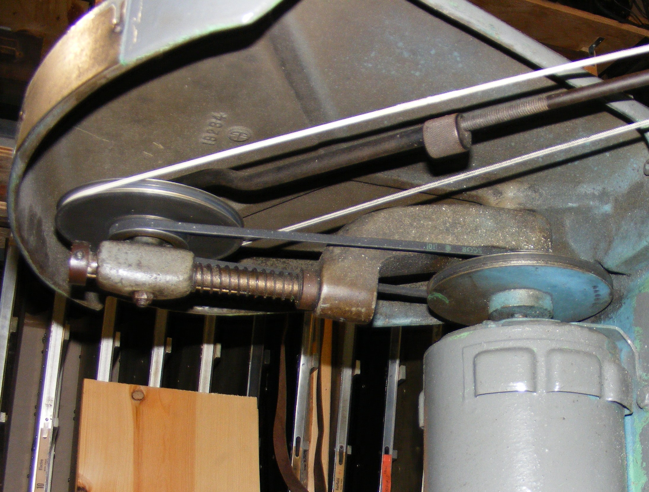
What we're interested in is getting power from the motor to the spindle. Here's a view from underneath which shows the overall transmission path.
The Motor has mounted on it the Motor Pulley (p/n 19241). This transmits power via the Motor V-Belt (p/n K-4298) to the Drive Pulley (p/n 19240). The Motor V-Belt is a conventional V-belt. From the Drive Pulley, the Spindle Belt (p/n K-5640) transmits power to the Spindle. The Spindle Belt is a round belt.
The Motor is just bolted rigidly the the main machine column. On my machine, it is a NEMA 48 frame motor. The motor frame is important as it positions the motor's shaft. In a NEMA 48 frame, the "48" indicates the distance, in numbers of sixteenths of an inch, of the centerline of the motor shaft from the base of the motor. Thus 48 sixteenths of an inch = 3 inches.
The Drive Pulley is held by an assembly consisting primarily of the Swinging Arm (p/n 19235), Drive Pulley Bar (p/n 19242), and Drive Pulley Bracket (p/n 19239). The Drive Pulley Bracket (on which the Drive Pulley is mounted) is pushed away from the motor by a Spring (p/n 13671, not illustrated in the parts list); this provides the necessary tension on the Motor V-Belt.
The Swinging Arm has no connection with the Motor or its shaft. Rather, it is mounted to the underside of the Tool Shelf on a stud, the Swinging Arm Stud (p/n 19244), with associated ball bearings and retaining rings. The shaft of the Motor must be arranged so that it is in-line with (though unconnected-to) the Swinging Arm Stud (which constitutes the axis around which the Swinging Arm swings). This would be an important consideration if re-motoring the machine.
The Drive Pully is connected to the Spindle by the Spindle Belt, as shown above, and by a belt tensioning arrangement which consists of thee parts, the Belt Tension Rod Sleeve (p/n 19246), the Tension Rod Collar (p/n 19247) and the "Tension Rod and Fork" (p/n CP-1862). These are shown below removed from the machine.
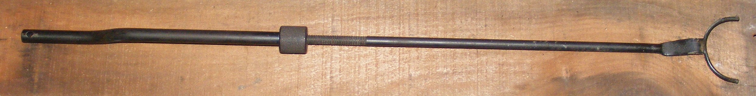
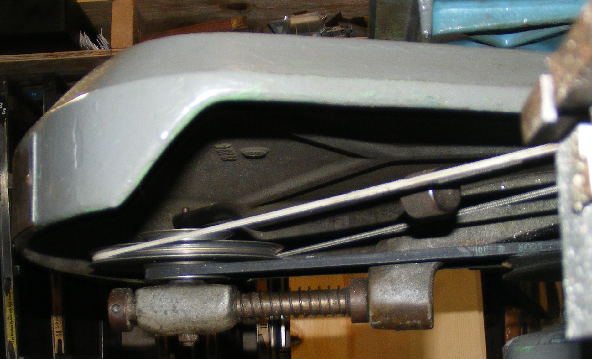
This assembly has a very interesting adjustment mechanism in the Tension Rod Collar; more on that later. First, though, let's see how the entire assembly fits into the machine.
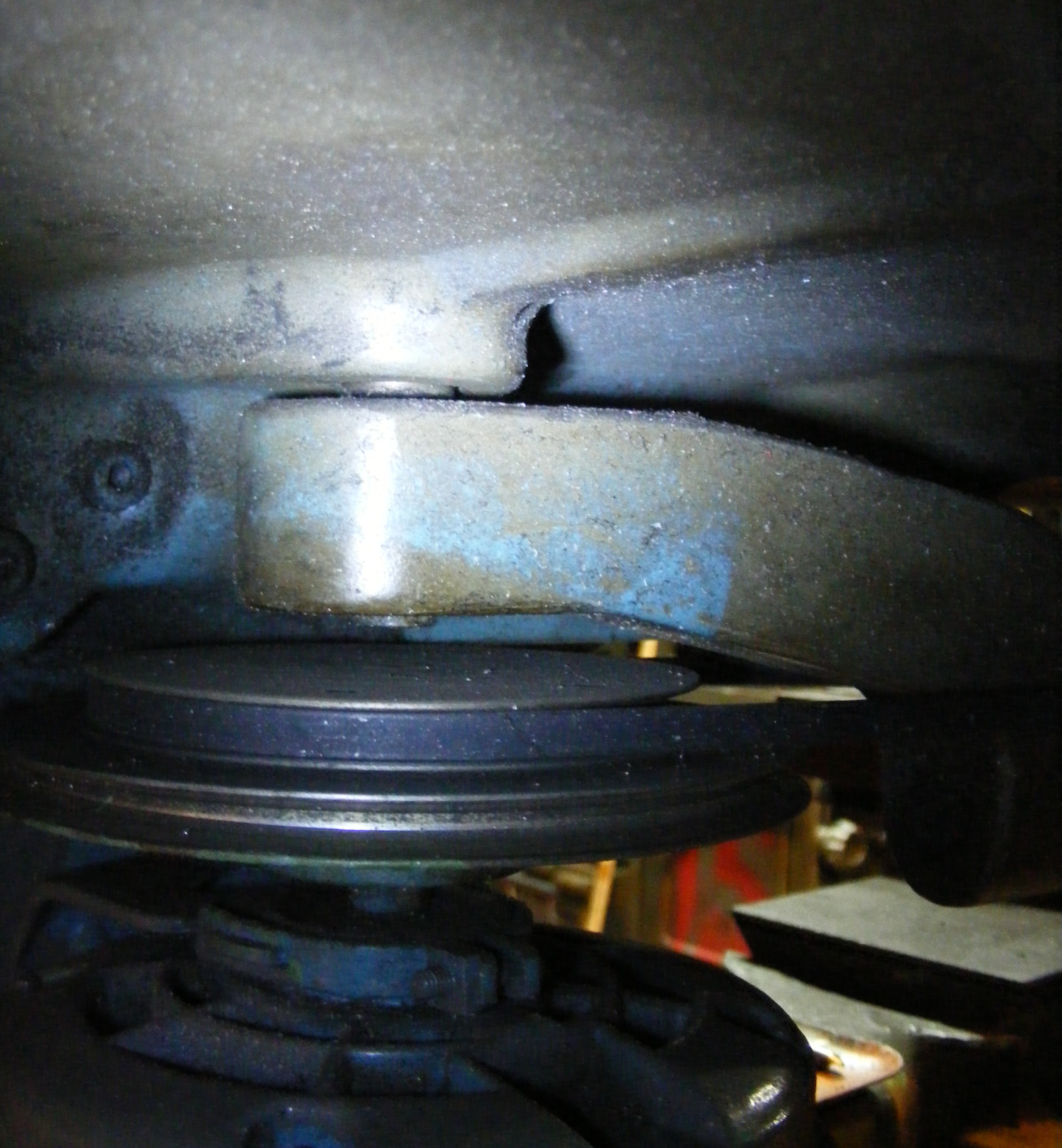
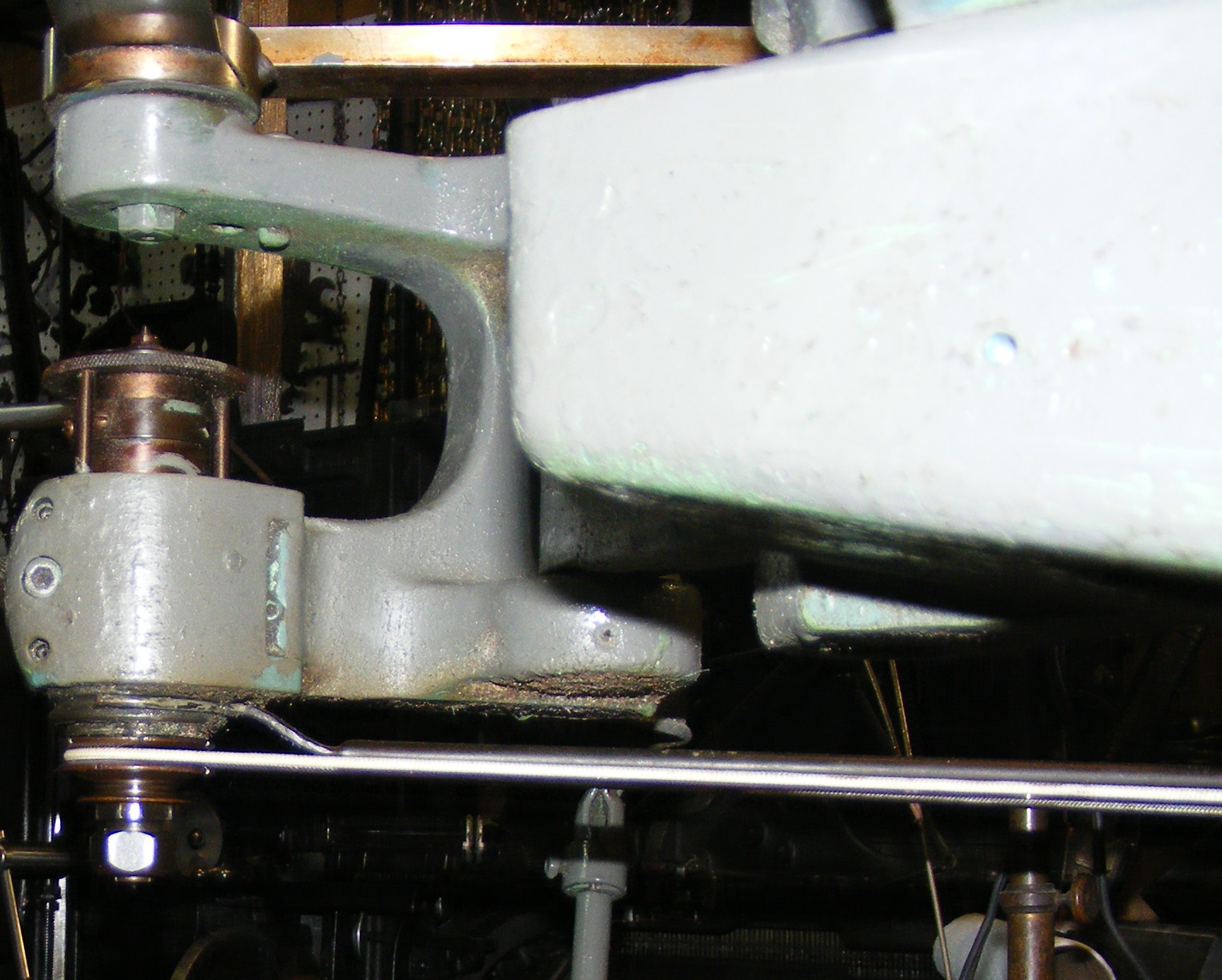
Note in the photo above that the Belt Tension Rod Sleeve has a hole drilled through it on its far end (the left side of the photo). This hole slips over an extension of the Drive Pulley Stud (p/n 19243) on which the Drive Pulley is also mounted. Here's a view showing it in place:
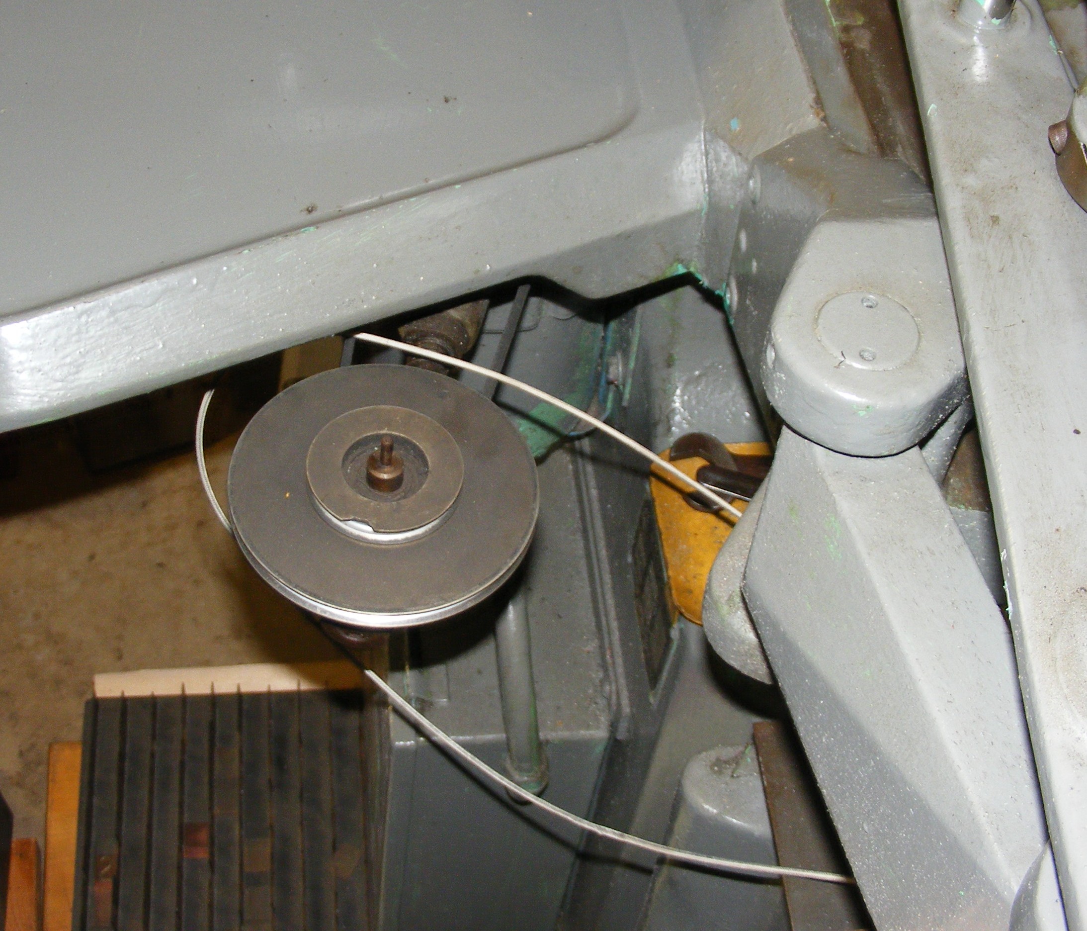
Here's a view of the Drive Pulley without the Belt Tension Rod Sleeve, showing the Drive Pulley Stud.
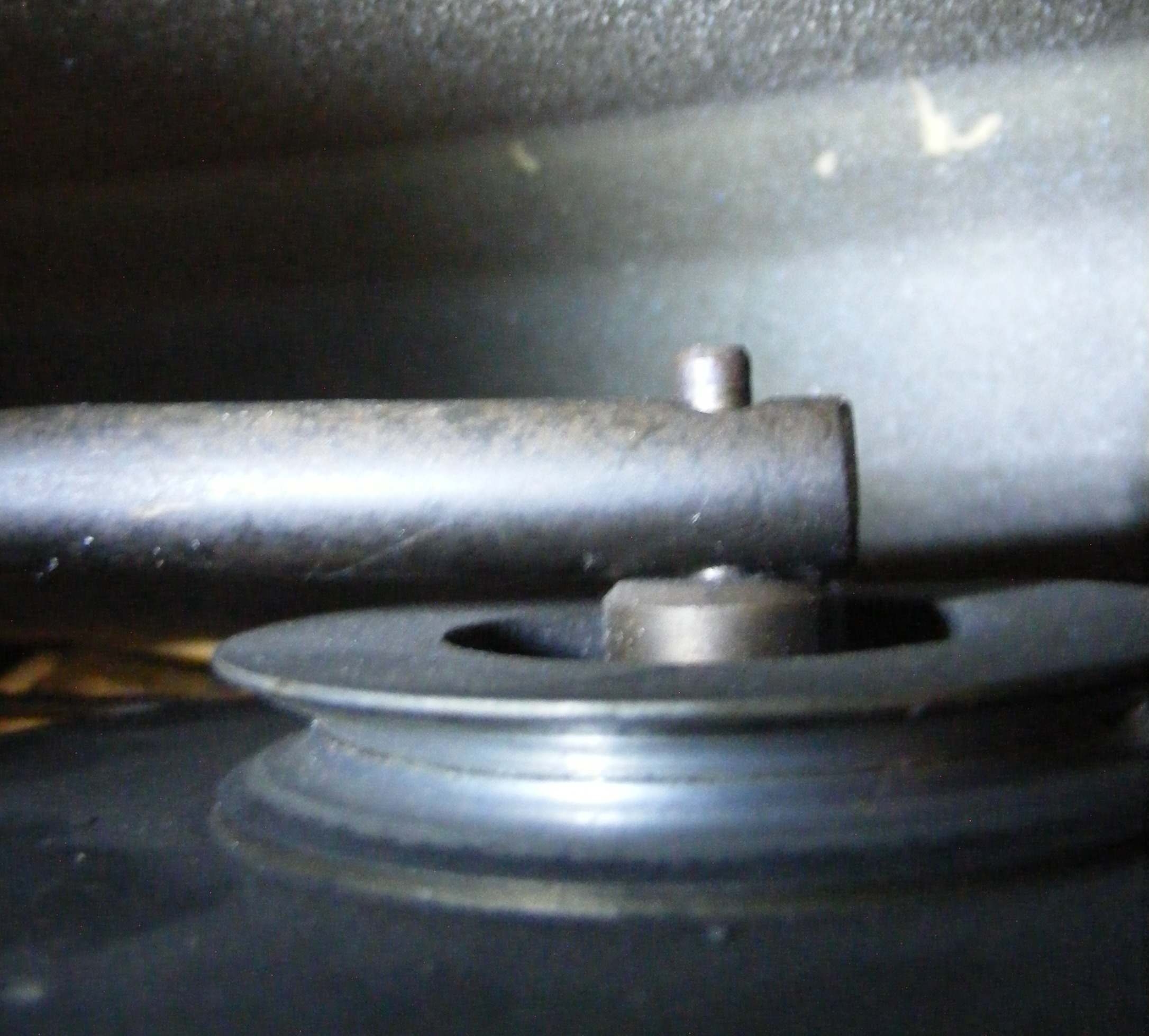
Here's a close-up of the Belt Tension Rod Sleeve mounted on the Drive Pulley Stud. Note that the Drive Pulley Stud does not rotate; the Drive Pulley is mounted on ball bearings around the Drive Pulley Stud.
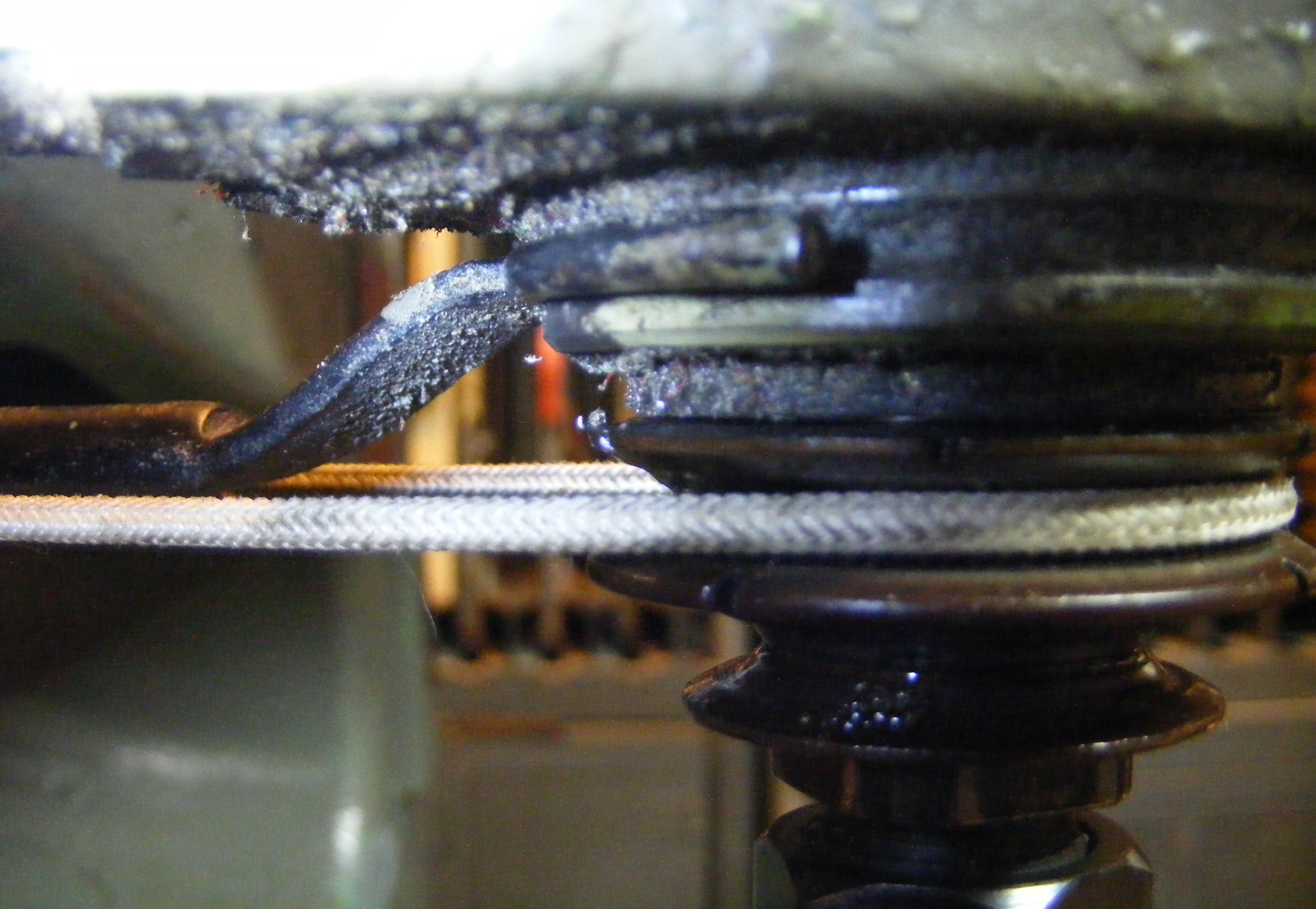
At the other end of this assembly, the "fork end" of the Tension Rod an Fork fits around a sort of a collar machined into the spindle itself (but not around either of the two steps of the pulley on the spindle - that's where the Spindle Belt goes). The part of the P1-2 Spindle Assembly with this collar is not called out with a separate part number in the parts list.
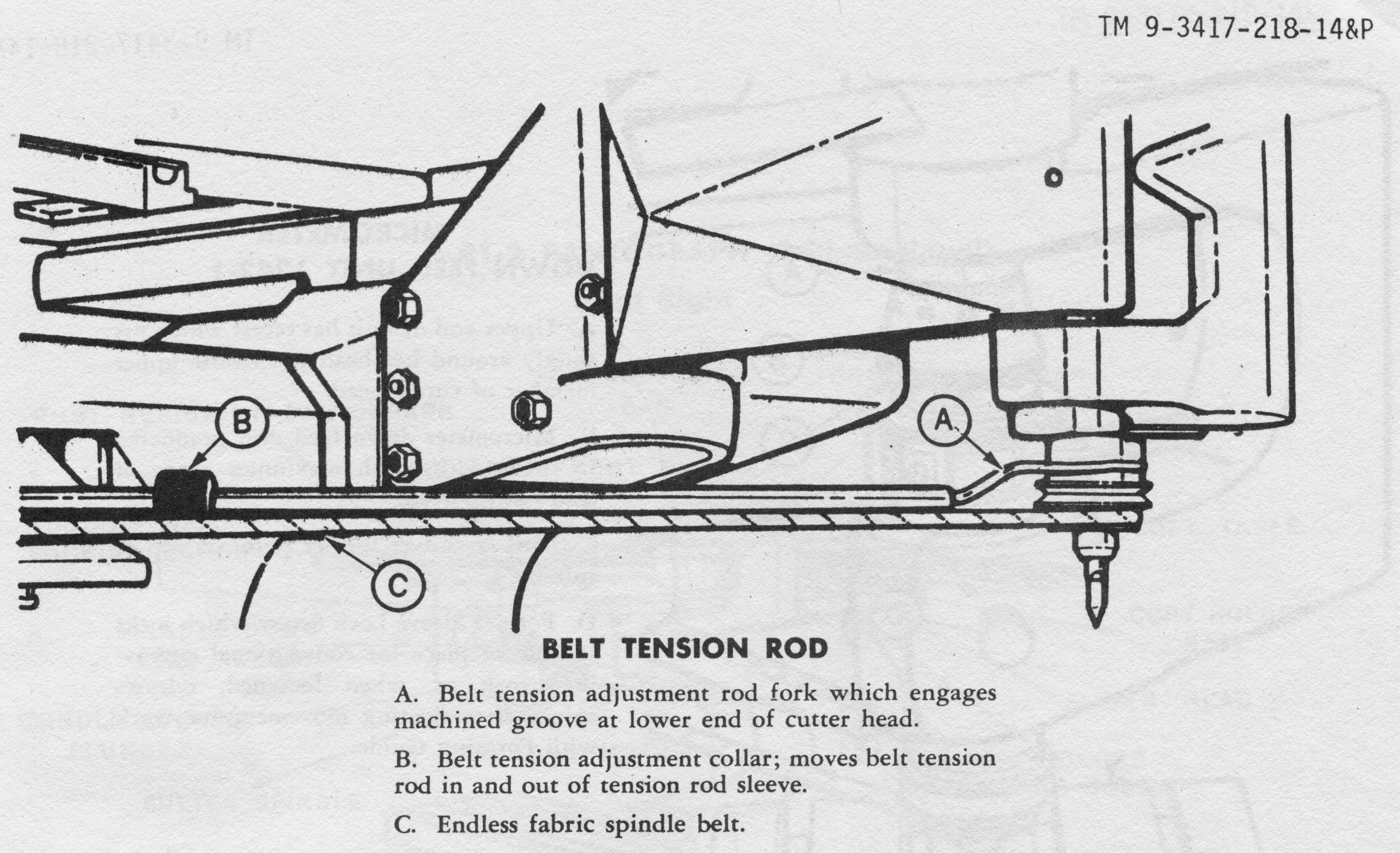
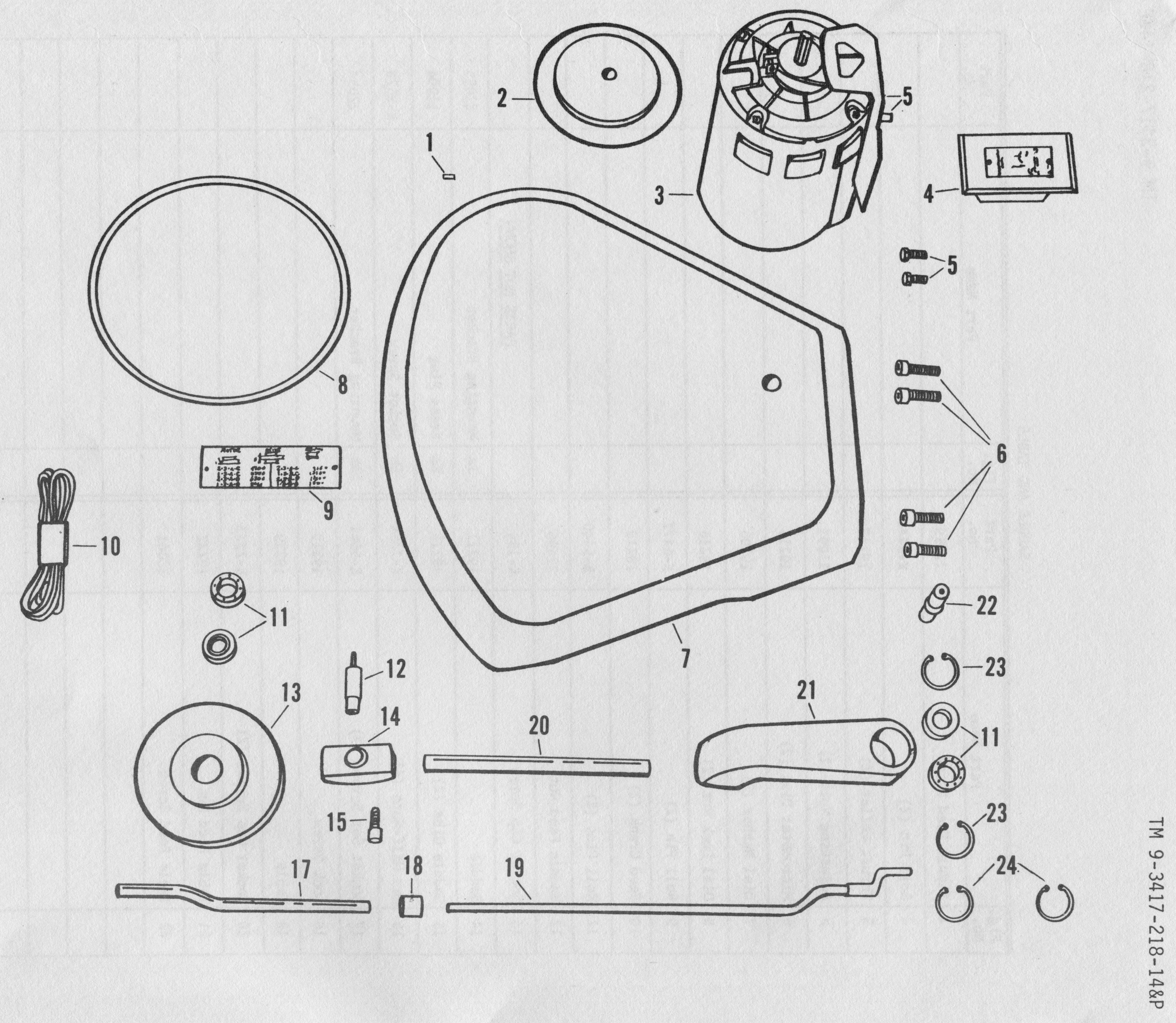
Here's the way it is shown in the Army's manual for the machine, TM 9-3417-218-14&P:

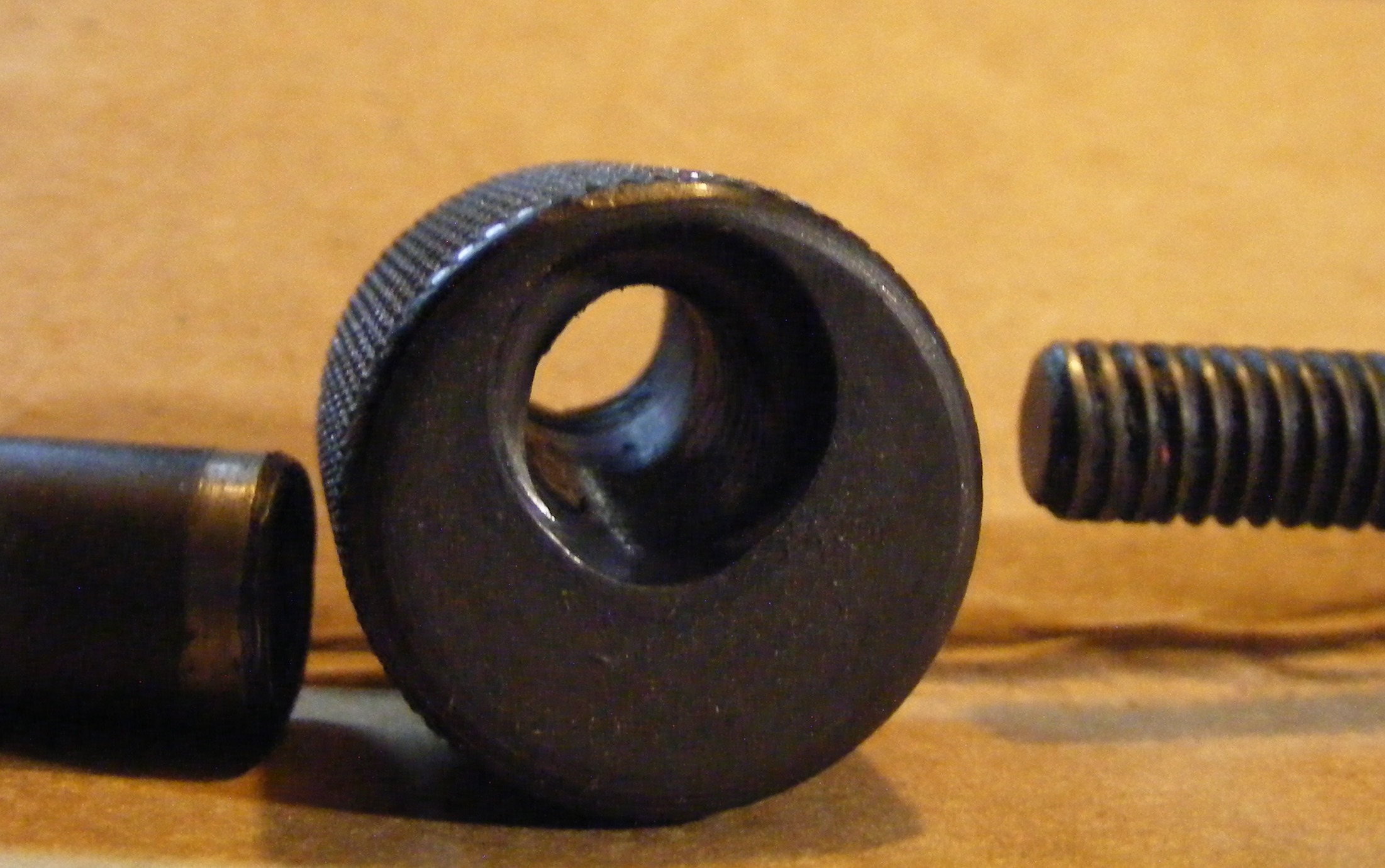
The clever part of this belt-tensioning assembly is in the middle, though. There must be some way to vary the length of this assembly, so as to be able to adjust the tension on the Spindle Belt. The Belt Tension Rod Sleeve, therefore, is a hollow tube (as its name suggests). The Tension Rod and Fork fits into this Sleeve and is threaded on this end. An internally threaded Tension Rod Collar is slipped onto the end of the Belt Tension Rod Sleeve and so, by rotating this Collar, the Tension Rod and Fork is moved in and out of the Belt Tension Rod Sleeve.
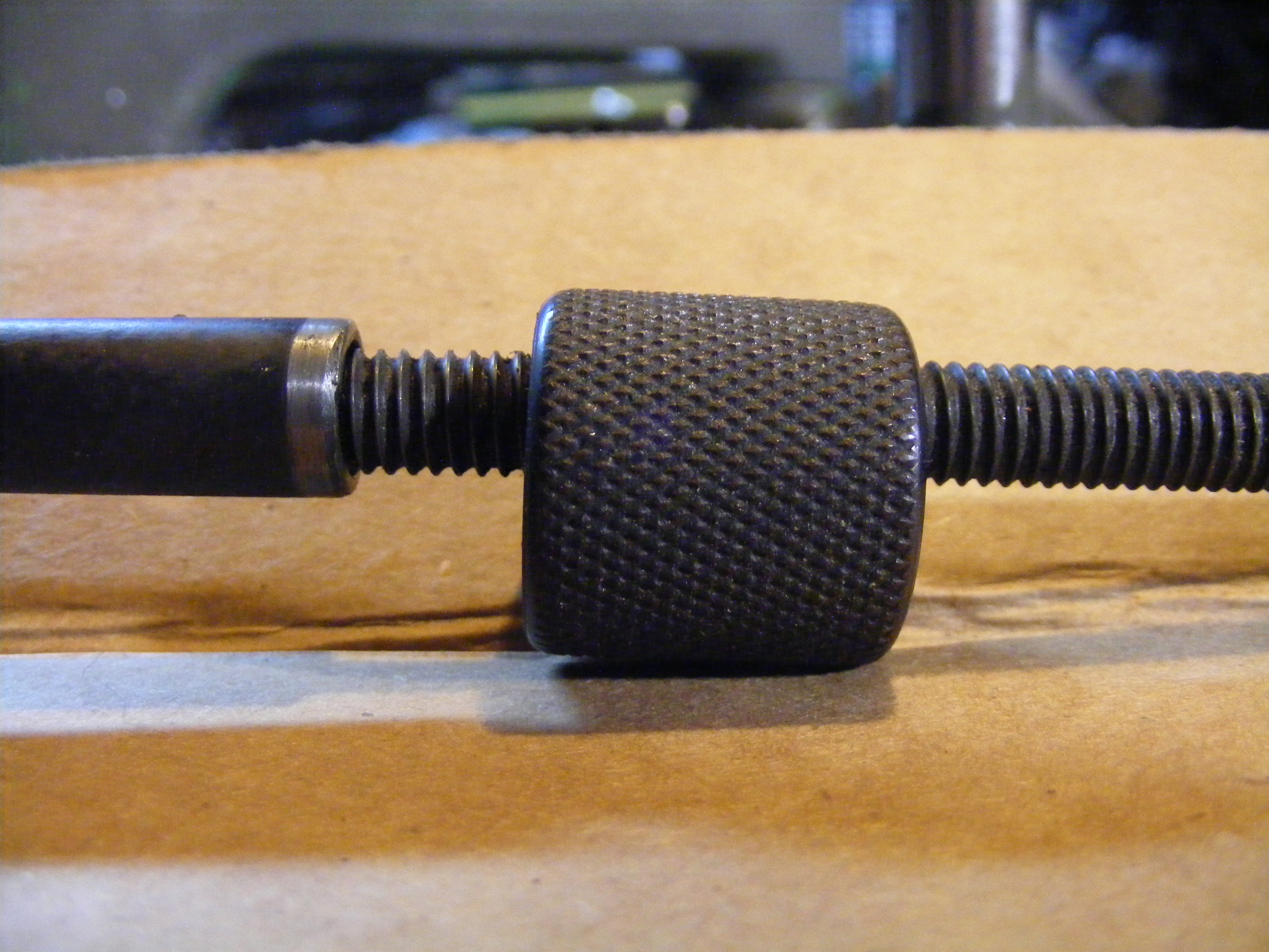
What makes this clever, though, is that the Tension Rod Collar isn't just drilled and threaded. Rather, the threaded hole through it is oval. This allows it to be lifted up out of engagement with the threads for rapid adjustment, or turned with the threads for fine adjustment. (It also allows the whole assembly to come undone and fly across the room when accidentally hit :-)
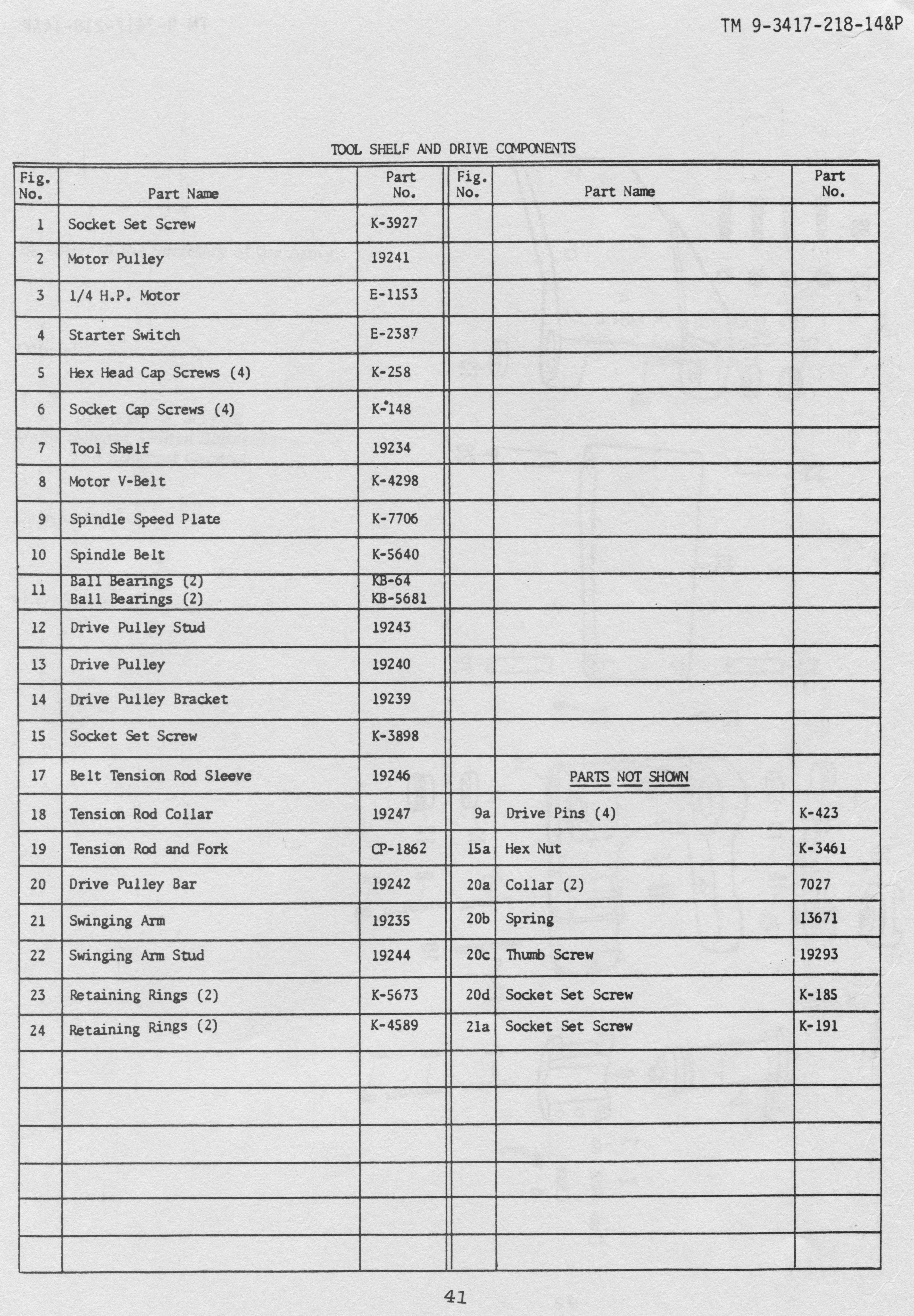
For reference, here are versions of the two pages in the parts list in US Army TM 9-3417-218-14&P which cover most of these components.
Finally, here's an overall view as seen in Gorton Form 1385, Pantograph Instruction Book and Parts Catalog. The belt-tensioning assembly for the Spindle Belt seems to be almost, but not quite, the same as that of the P1-2. (The tensioning Sleeve and Rod are present, but the Collar between them looks in the 3-U as if it's simply a collar with an internal thread and perhaps a locking screw.) The swinging arm (p/n 7106-A in the drawing above) looks to be a bit different (no tensioning mechanism is shown for it).

The image above is taken from the original 1935 release of this manual (simply as Form 1385 with no letter suffix to the form number). The other copy I have is 1385-E, from 1950. The difference between the two is that 1385-E has a lubrication schedule (which is important, but which isn't relevant to the present discussion).
Gorton Forms 1385 and 1385-E are in the public domain due to the expiration without then-required renewal of their copyright. The image from Form 1385 here was scanned by me from an original copy in my possession. These scans remain in the public domain.
US Army TM 9-3417-218-14&P is in the public domain as it is an official publication of the US government. The images from it here remain in the public domain.
The photographs on this page were taken by me of my P1-2. They are licensed for re-use under the terms of the same Creative Commons "Attribution-ShareAlike" license which governs this page as a whole.All portions of this document not noted otherwise are Copyright © 2011 by David M. MacMillan and Rollande Krandall.
Circuitous Root is a Registered Trademark of David M. MacMillan and Rollande Krandall.
This work is licensed under the Creative Commons "Attribution - ShareAlike" license. See http://creativecommons.org/licenses/by-sa/3.0/ for its terms.
Presented originally by Circuitous Root®
Select Resolution: 0 [other resolutions temporarily disabled due to lack of disk space]