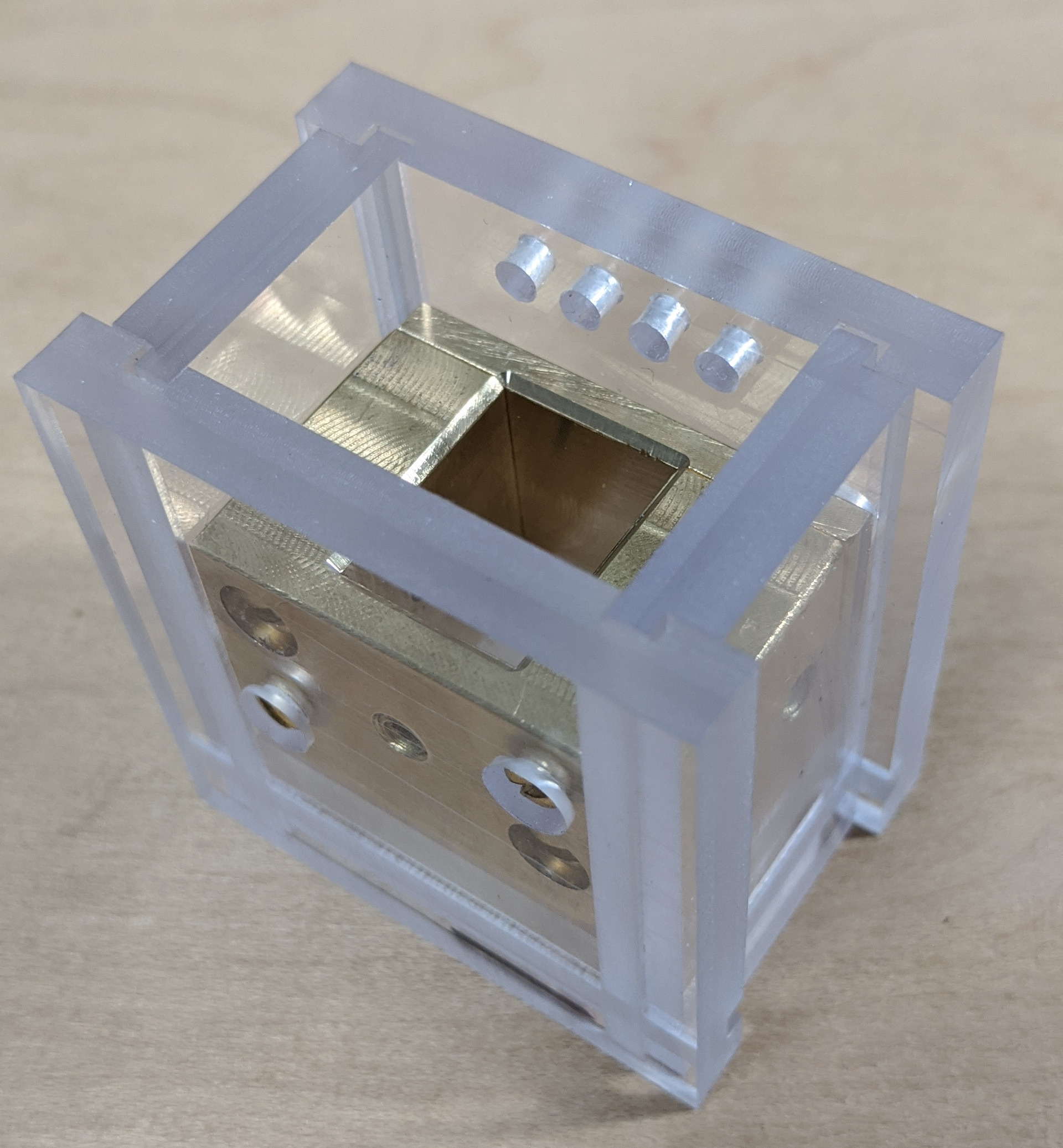
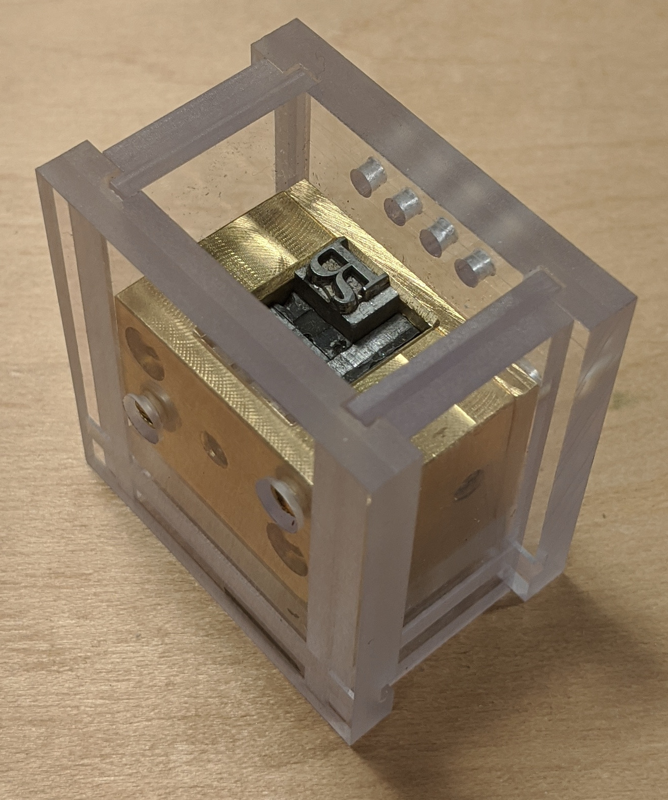
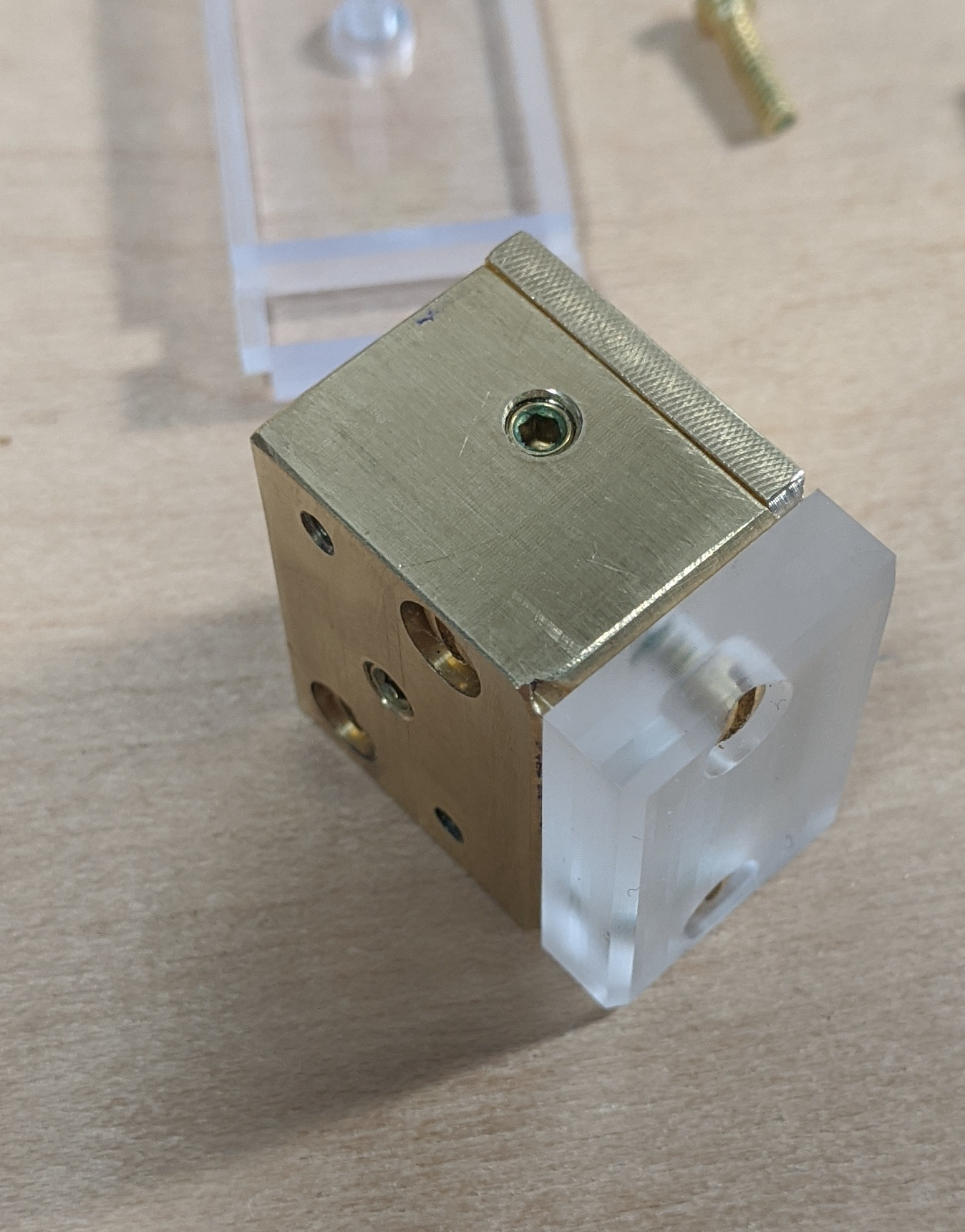
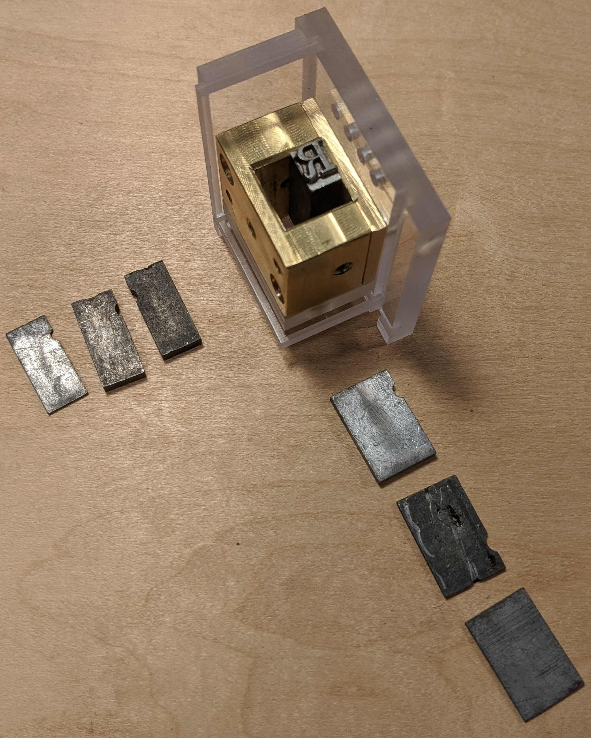
Here's an actual workshop project - the first that I've posted to these Workshop Updates. Explaining exactly what it is (which I'd love to do, in detail, at length) would require quite a bit of background information. In the briefest description: it is a fixture used in a process of making type using (at one stage of the process) eletrodeposition. Here it is in completed form (left) and filled with a type from which to make a matrix (right):
The basic idea is that after some further preparation (waxing to make parts of it nonconductive, bronze powder to make other parts conductive, and a hookup wire) this fixture will go into a copper electroplating bath. There the rectangular space above the type will be filled with a heavy plating of copper (the term in industry for this process today is "electroforming"). Once it's thick enough, this copper deposit will be removed and machined to final size as a matrix.
(This particular method, as described to us in a single surviving document, also requires that the shoulder of the pattern type be cut back by about 4 points. This would of course preclude its use on originals of historic importance. (However, since the electroforming process always carries a risk of destroying the original if it does not go well, it should never be used on unique or historically significant types in any case.) I have not yet cut back the shoulder of the type shown here.)
This is the method used by the late Andrew W. Dunker to make matrices. It differs from the methods more commonly used (since at least Thomas Starr's 1845 patent), in which a brass blank (or "planchet") with a hole in it supplied most of the mass of the matrix. (In the more common method, only the area directly around the type was electroformed into the hole in the planchet.) Dunker's method is almost certainly more difficult (I'll know for sure after I've done both), but it produces a beautiful, solid matrix. Here are genuine Dunker matrices shown in use by me during my apprenticeship at Skyline Type Foundry in 2010. These matrices (and the ones I will make) are of a form appropriate for use on the Thompson Type Caster. (Although you can't make it out in the photographs, the face is Nestor Script, Barnhart Bros. & Spindler, Chicago, 1895.)
If you are a typefounder who knows anything about machining, Dunker's matrices are astonishing to behold.
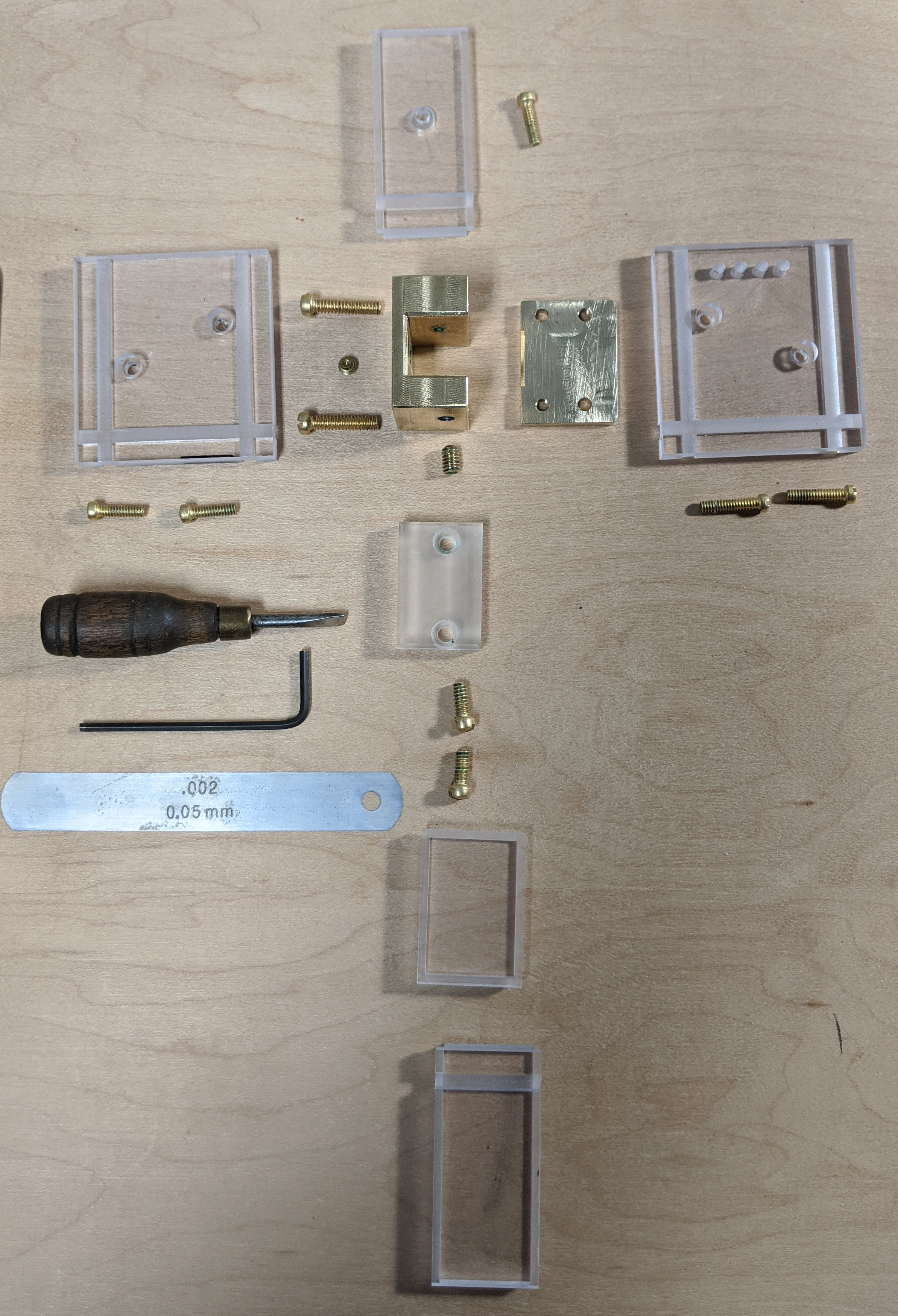
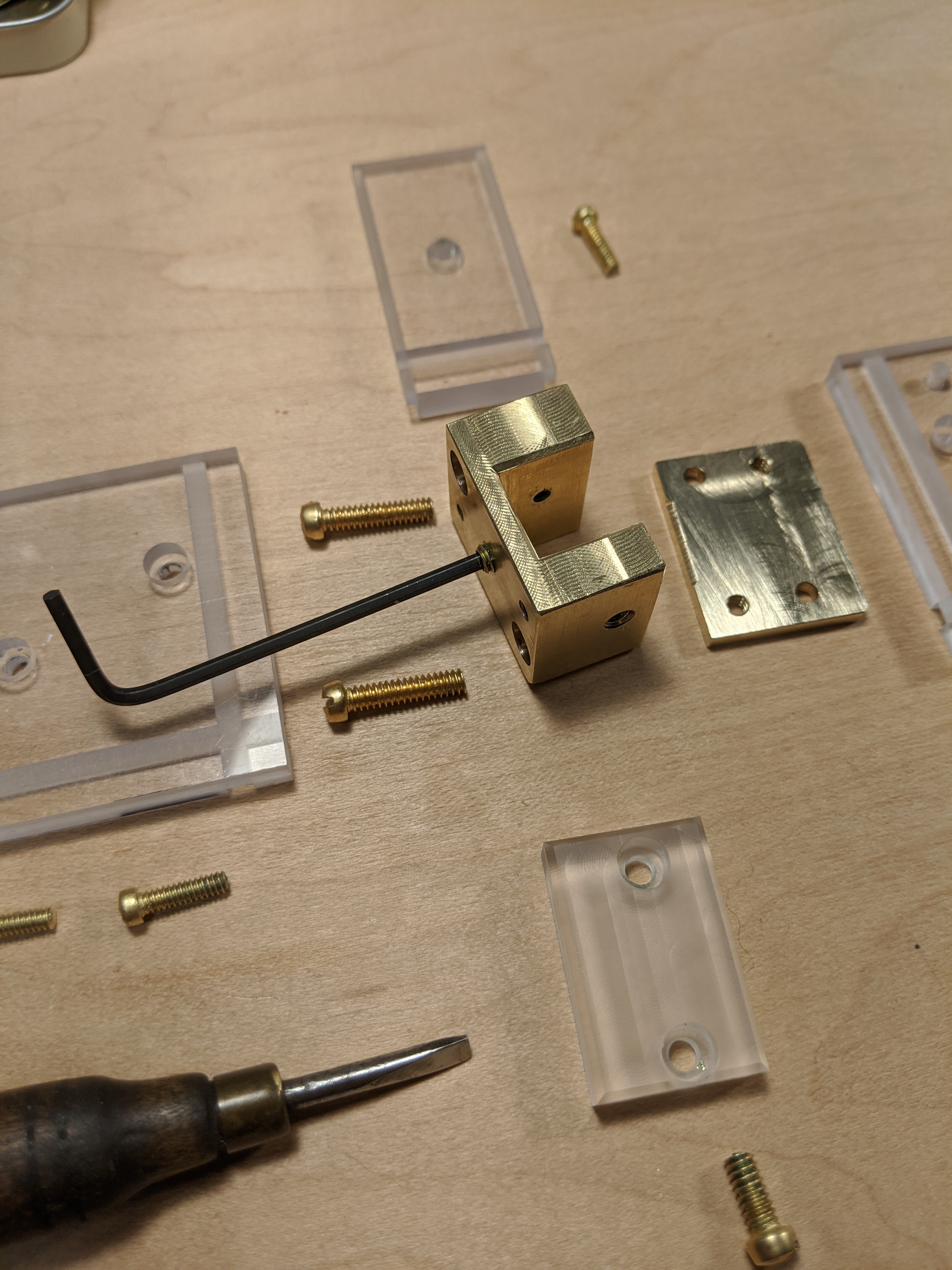
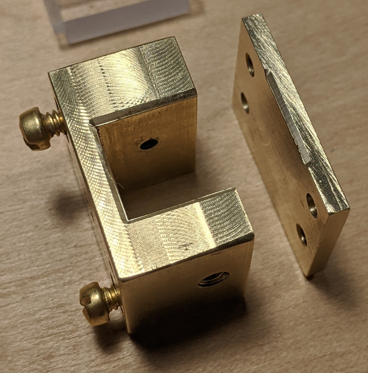
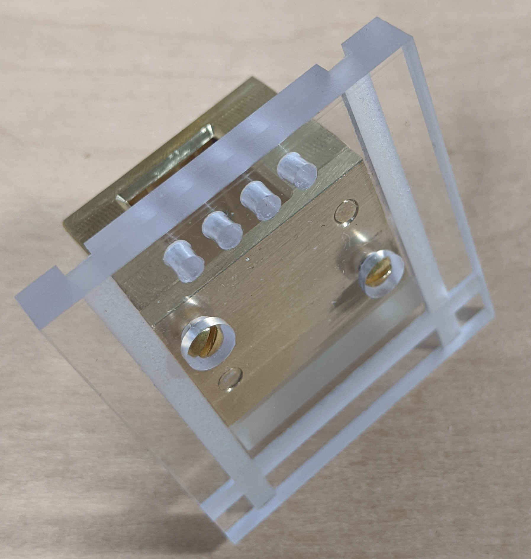
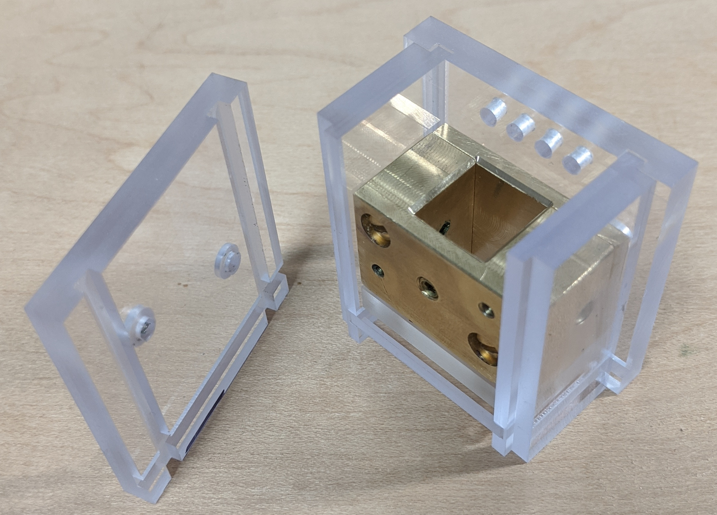
Here are all of the parts of my new Electroforming Case laid out. (Dunker himself probably called it a "Deposition Case." The late Paul Hayden Duensing, to whom we owe much of our information on Dunker's method, called it a "Depositing Case.") A few of these items were not made by me. The screwdriver came from my box of old small screwdrivers, and the hex key and feeler gauge are obviously commercial items. The screws are brass socket head set screws (grub screws to the English) and fillister head screws from McMaster-Carr (though they do not have true fillister heads with parallel sides, and in any case they should have been cheese head screws; you just can't get proper 19th century screws anymore). For scale, they're 4-40 and 6-32 UNC thread. I've shortened several of them from their stock lengths. I machined the two brass components and the six plastic ones. Five of the six plastic pieces are polycarbonate. The piece shown in the middle with two holes in it is cast acrylic. Polycarbonate is much nicer to work with, but nearly all plastic stock sold today is sold under-thickness. This didn't matter for the outside components, but the bottom of the inner case had to be made to dimensions. I happened to have a sufficiently thick piece of acrylic - it's actually nearly the last of some scrap that my late wife Rollande and I salvaged from a dumpster in Los Angeles over thirty years ago. Even simple things have their history.
For an experienced machinist, this project would be very simple. It involves nothing but ordinary milling and drilling operations at a convenient size in easily worked materials. However, I am not yet an experience machinist, so for me it was a "learning experience" (as the phrase goes). I was able to hold most dimensions to within 0.001", but even so it required a little bit of hand fitting at the end in order to assemble smoothly.
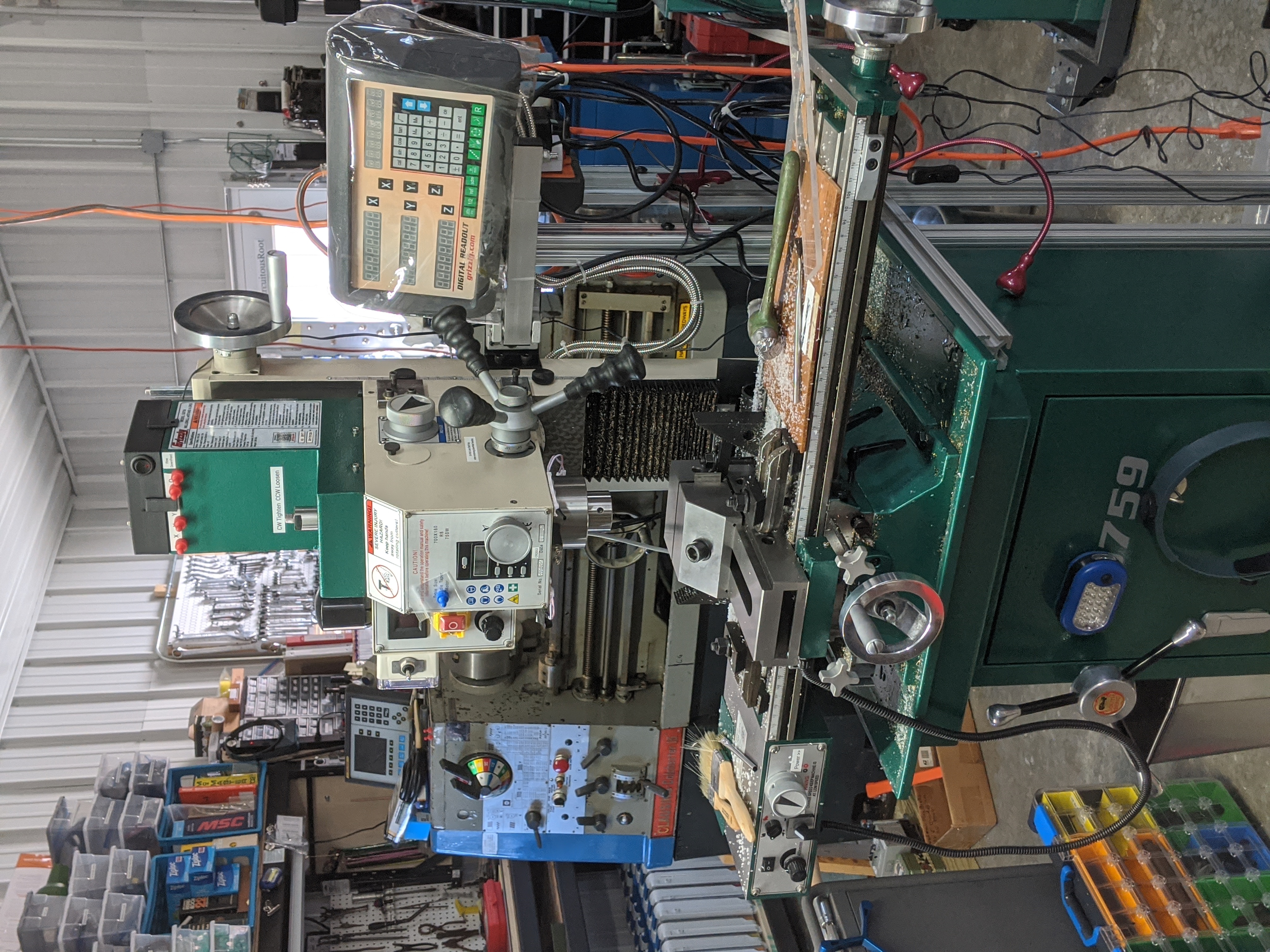
Here's the machine I made it on. It's a Grizzly (brand) G0759 benchtop milling machine (mounted here on a pedestal). The G0759 is the same as their popular model G0704 but has a factory-installed Digital Readout (DRO). I find the DRO to be essential, and in practice never even use the graduations on the handwheels. This mill is Grizzly's version of a very common Chinese design known generically as a "BF20". (I have been unable to track down the origins of this model designation. With my love of well-researched detail, this bothers me.) Behind it is my Clausing-Colchester 13" lathe (which is really a Colchester Master 2500, made in England).
Although I've had this mill for a couple of years now, this is the first complete project I've finished on it. I learned a lot not only about machining but also about this particular milling machine. The quick summary is this: for what it is, it's a pretty good machine. The caveat is "for what it is." The main issue is rigidity. By this I mean two things: First, the machine will flex. This is true of all machines (the great Youtube machinist Stephen Gotteswinter has observed, wisely, that we only think our machines are made of metal - in fact they are made of rubber), but a lightweight machine such as this will flex more than a full-size floor-standing knee mill. But secondly, and more importantly, I mean a lack of rigidity in alignment. Out-of-the-crate, this mill is good for work within about 0.005". That would be fantastic for a woodworking machine (a "scant sixty-fourth" is about 0.015"), but hasn't been acceptable to a machinist since Maudslay in 1805. With careful adjustment, it is possible to bring the machine into alignment to within 0.001 (in fact, for one brief, shining moment I could hold 0.000,1" (a "tenth") over two inches). But the alignments on the machine are mostly held in place by simple friction (and sometimes shims, which are better). It simply will not stay aligned. Yet it is possible to produce accurate work on this machine. The methods you use are the same as those used by an experienced machinist to produce accurate work on a worn-out machine: you anticipate the errors and compensate for them. You also end up doing a lot of measuring of the part on the machine (which takes up much time).
The saving grace of this particular machine is that the DRO is spot-on.
I didn't take any photographs during the machining process (because these were such ordinary processes). [I hate it when they say things like that in 18th century technical works.] Here are a few shots of the finished article, the better to show its construction. As is obvious from the photographs, this first effort is by no means a fine machining accomplishment. To a trained eye it is a good illustration of just about every mistake you can make while still producing a (probably) functional result.
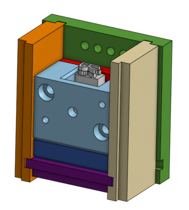
It is really a very clever assembly. The CAD model can be a great help in previsualization, though there's still no substitute for making the real thing.
(Note: It turns out to be rather difficult to model a type realistically in CAD. The version above isn't right, but it is sufficient for its purposes. But whatever you do, when illustrating type-making, never select a sort which has symmetry in either the set-wise or body-wise axes. Historically, 'H' and 'M' have been very common, but very bad, choices.)
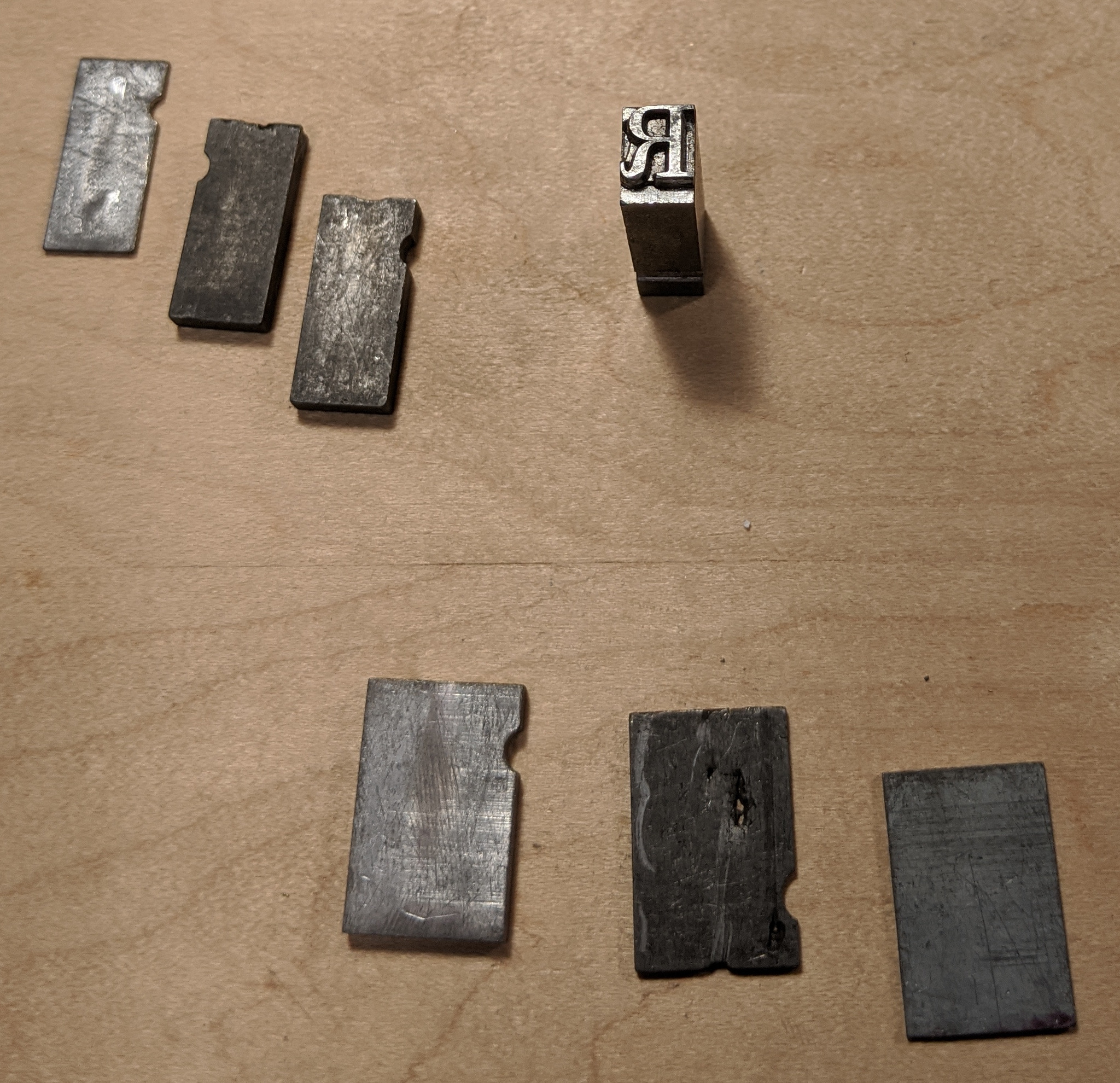
Here are two views of a type and its placement in the holder. This particular piece came out of a box of scrap type in my foundry. I'm not entirely sure what it is (I'm really not that good at typeface identification). It's probably a Lanston Monotype face; it looks like a Clarendon to me. The empty space around it is filled up with spacing material. This is something that a typefounder would simply be expected to have on hand.
A close look at this type will show that it has a damaged face. If the electroforming works, this damage will be reproduced perfectly in the matrix and I'll be able to cast brand new damaged type from it.
It might be appropriate to point out the purpose of this exercise. I'm trying to do what Dunker did, in a way which is as close as is reasonable to they way he did it. I'm not trying here to improve upon his method or to make matrices by any possibly better or best method. I'm doing this because, well, Dunker was a pretty smart guy and I'd like to experience his process in detail before embarking upon any changes. We know from the surviving mats that Dunker produced beautiful work; I'd like to learn how he did it.
On Not Thinking Things Through
One question which (to be honest) I hadn't actually thought through until after I made this deposition case is intended depth of drive.
The intended matrix "depth of drive" (depth of the casting cavity in the mat) is not actually specified on Dunker's drawings. Most of Dunker's mats have an 0.043" depth of drive because that's the mold he had on his Thompson, but Duensing's notes on how to use a Dunker electrodeposition case seem to be for these drawings and describe the making of 0.050 drive mats. I have both 0.050" (Lanston display) and 0.043" (Linotype) molds for my Thompson, but there are some issues with my 0.043" equipment. I'll be trying to make 0.050" mats.
It comes down to whether or not there is enough deposited copper on the face-side of the mat to mill it down to height. I think that there will be, but I won't know for certain until I try. Even if the mats end up being under-depth, though, it doesn't really matter. I'll learn just as much about matrix forming (I'll just end up with under-height type). I can also always mill the holder in the case down slightly to produce a deeper depth of drive.
The next step is to revive Rollande's old electroplating setup and try to make a mat. I hope to do this soon, but make no guarantees. This is a fun project, but it is not on the "critical path" for my central priority right now: the 2020 ATF Conference.
Naturally, a complete writeup with sources and technical drawings is in preparation. Here are links to the draft versions of the writeup and drawing portfolio (with an emphasis on draft - these are incomplete).
The CAD model and derived drawings were done in Onshape and are freely available at: https://cad.onshape.com/documents/0c412a5cb0e263a0c7c3711a/w/ae499bc626bab1ca697671e0/e/3dc0540e4ed9ffe5bfb65163 or just search cad.Onshape.com for "Dunker Matrix Deposition Case".
In starting out something such as this series of Workshop Updates, it is interesting (well, to me at least) to wonder if it is worthwhile. One friend described my recent decision to eschew social media (and do this instead) as "courageous." It is an alarming indication of just how powerful the social media have become that simply not participating is perceived as an act of courage.
But I'm not sure how I could do anything else. This present posting is just about as short as I could make it while still conveying enough to be worth saying anything at all. Would it fit in Instagram? Twitter?
Yes, it does take longer to do. It requires actual writing (and image editing, which even if only crudely done takes longer than writing). But, then again, this is the bumper sticker on my car:
(Mostly when you click on images on my pages you get a bigger version of the image. The image above, however, is a link over to Viroqua Creative Workshop LLC, who sell this bumper sticker.)
As a postscript, the more elaborate section dividers will be familiar to anyone who has read John Crowley's novel Little, Big in its 1981 or 2006 trade paperback editions. I've tracked most of the ornaments used in these editions back to their 19th century sources (although as used in the printing of Little, Big they almost certainly came from a photocomposition service). The ones used here were from a series of Head and Tail Pieces by the MacKellar, Smiths and Jordan type foundry in the late 1880s or early 1890s.
All portions of this document not noted otherwise are Copyright © 2020, 2022 by David M. MacMillan.
Circuitous Root is a Registered Trademark of David M. MacMillan.
This work is licensed under the Creative Commons "Attribution - ShareAlike" license, version 4.0 International. See http://creativecommons.org/licenses/by-sa/4.0/ for its terms.
Presented originally by Circuitous Root®