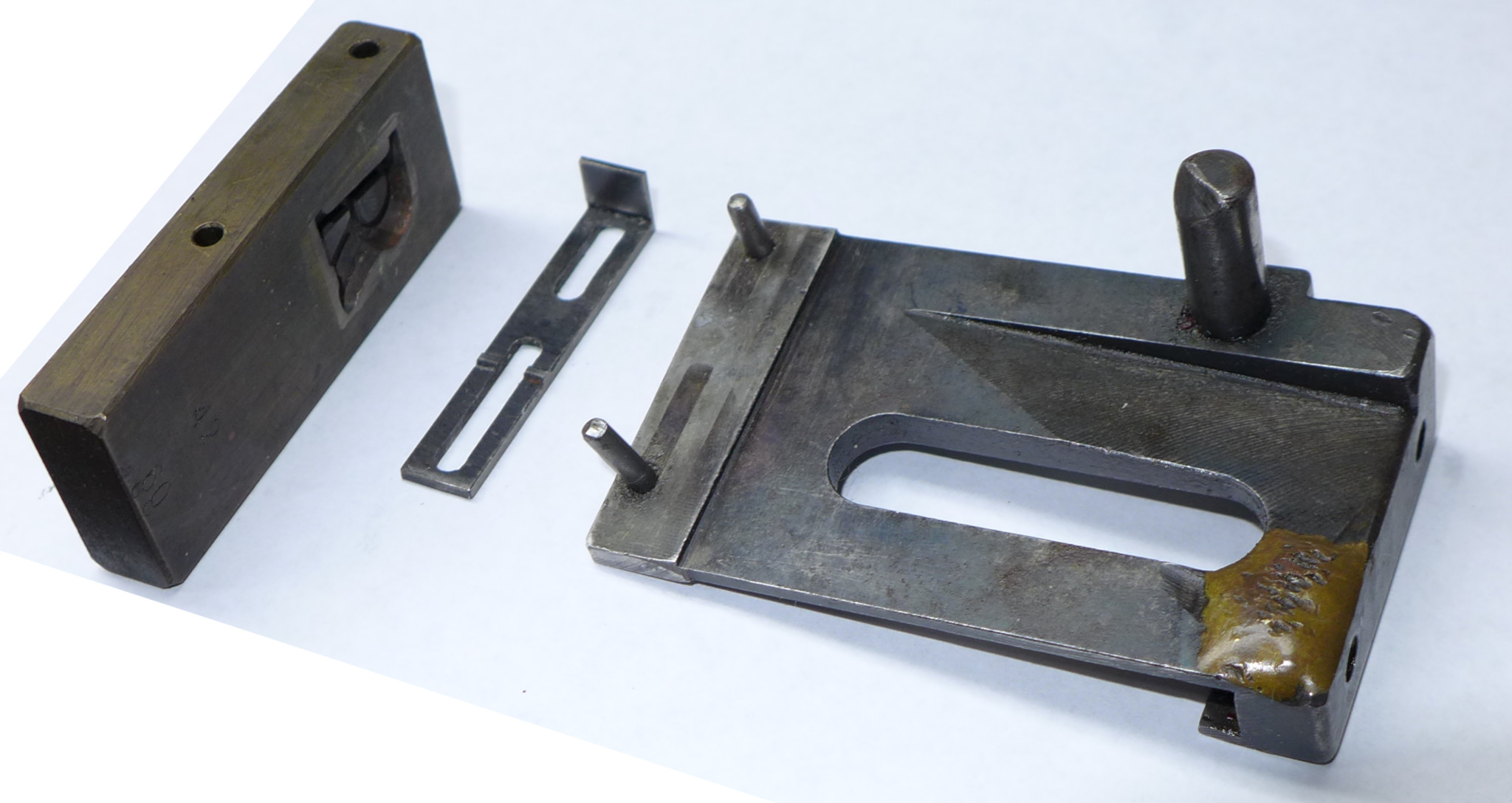
One of the parts which I need to make in order to run the 60pt Barth Type Caster is the "Shoe" in the matrix equipment. It is a reasonably complex component.
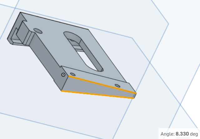
Barth Notes: This Barth is a No. 3 1/2 machine equipped with a B4-drive 60pt mold. Only one other No. 3 1/2 Barth exists, the 72 point machine. The Shoe and Slipper for the 72pt machine exist (and are shown in the photo above), but they have not survived for my machine. In the photo above left, the "Shoe" is the largest item. The "Slipper" is the two-slotted shim which fits between the Shoe and the Matrix. The Matrix is here shown with its side-holes up; in use these would be down, fitting over the two posts on the Shoe (and the casting cavity of the matrix would face away from the Shoe, into the mold). The matrix shown is a 60 pt mat (Goudy Handtooled Italic.) In the 3D CAD model of the Shoe (above, right) it will be clear that I have simplified it slightly. I don't think that I'll need the triangular relief on the top surface. I'll find out when I try it.
Anyway, this posting is not about making this Shoe. It's about making tooling which will let me produce the unusual angle the Shoe requires: 8° 20′ (8.33°).
There are any number of ways you could set up to mill this angle. Classic options include:
I chose a different method: making custom angle blocks. Mostly I did this because I thought it would be fun to make the angle blocks (it was). This method also has the advantage that, once made, these angle blocks may be used repeatedly and are much faster than the other methods.
But how do you make an angle block for a bizarre angle such as this? The machinist Joe Pieczynski of Advanced Innovations, LLC in Austin, TX, described a really elegant method in one of his Youtube videos: "Making super accurate angle cuts on the mill - GREAT TRICK !!", https://www.youtube.com/watch?v=lDwAzcSUVtI (posted 2016-08-20). You should watch it (and all of his other videos - especially the one about thread cutting without panic).
In general I like Pieczynski's approach in his videos because he thinks things through clearly and comes up with extremely intelligent solutions. He uses his brain rather than just throwing a computer at the problem. (He also probably did really well in geometry in school.) In this case, his method allows you to make an angle block for any angle you desire using only common shop tools (no angle measuring tools at all). It's simple (once he shows it to you):
1. Square up some piece of stock which will become your angle block.
2. Calculate a right triangle which fits inside this piece, which is square with the piece, and which has your desired angle.
3. Accurately drill and ream two holes at the acute vertices of this triangle. Make them some convenient diameter for which you have accurate dowel pins.
4. Put two dowel pins through these holes and use them to support the block on top of the milling vise. If you don't have precision dowel pins, most quality end mills are good substitutes).
5. Mill the top flat - and there's your angle.
It's so elegant that it makes you feel good just thinking about it. This method really seems as if it ought to be an old toolmaker's kink. But I have a reasonable collection of old books on toolmaking and fine machining and I cannot recall ever having seen it before. Thanks, Joe.
I'll add only one thing to his method. He does the trigonometry by hand (of course he does; he's good). I found that it's faster (for me) to throw together a very quick CAD model and let the CAD system calculate the dimensions for me. (So, yes, I'm cheating a bit.)
I've constructed this example with a "hook" in it. Pieczynski mentions this as an option late in his video.
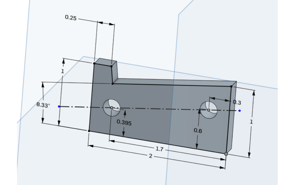
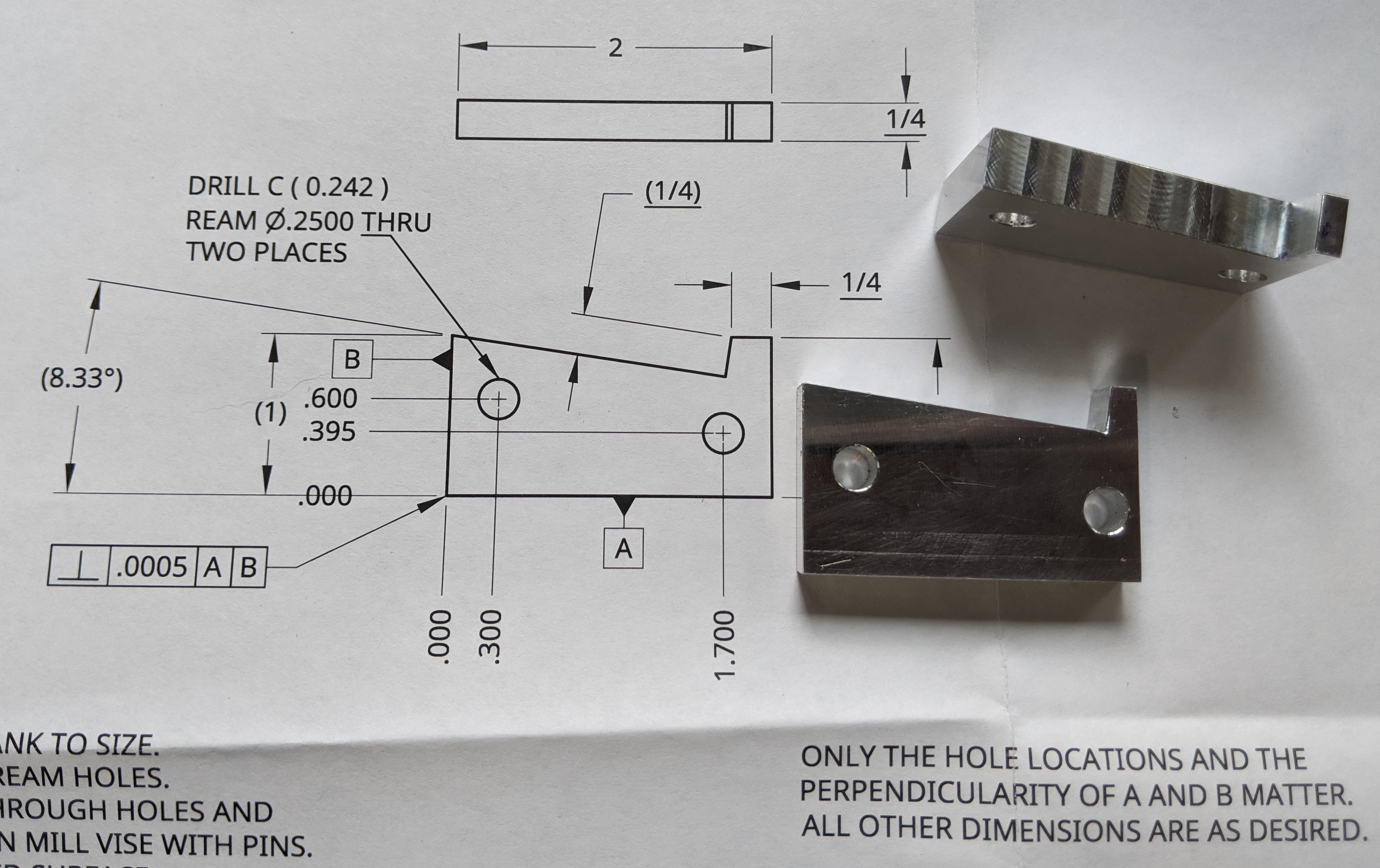
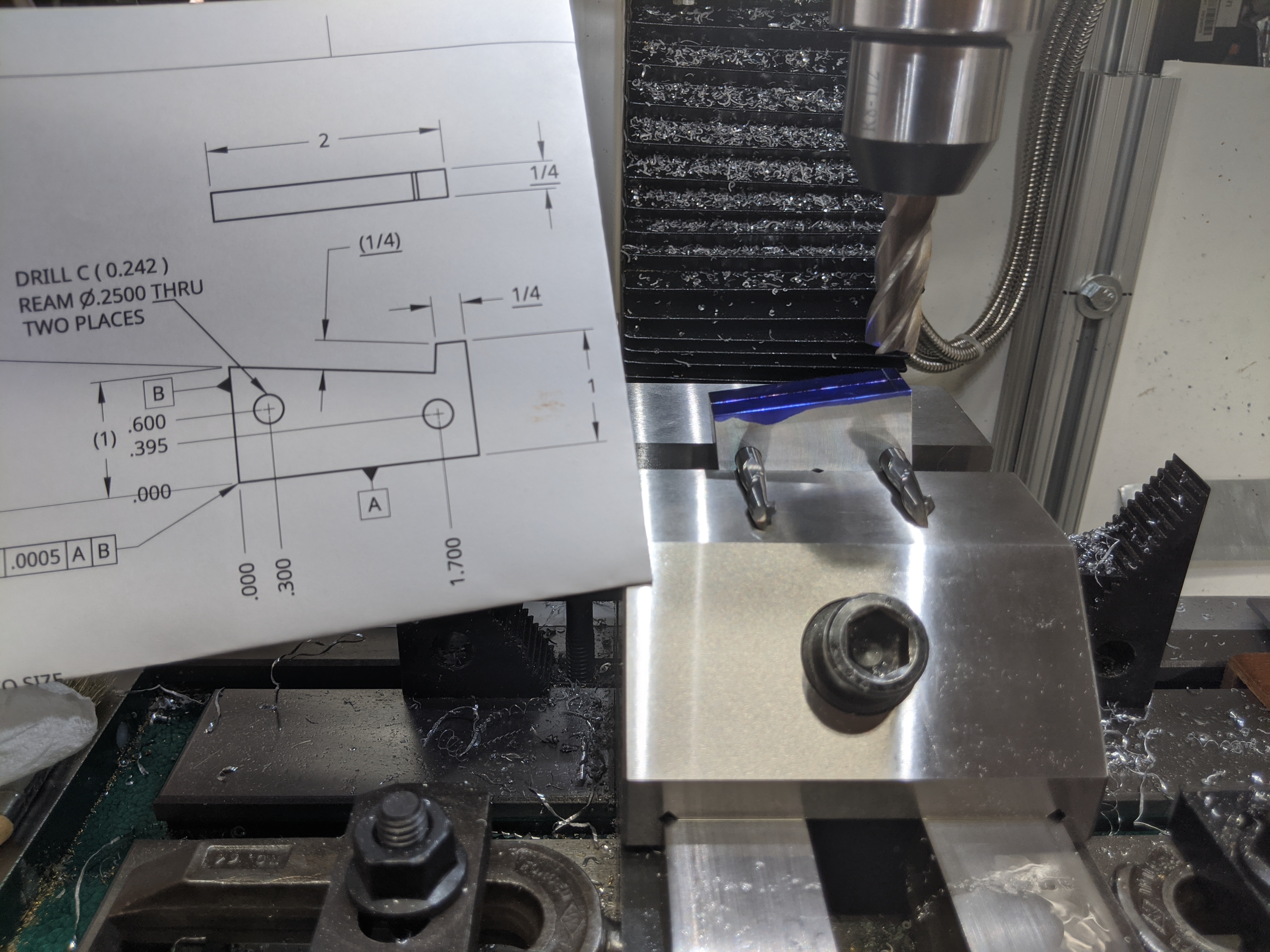
So here is a view of the CAD model. It's 3-D, but really this is a 2-D part. The only trick to doing the CAD model is this: Positioning the holes takes four dimensions. Make three of them easy (0.3, 0.6, 1.7 in this example) and let the CAD system compute the remaining one as it falls (0.395 here). The exact positioning of the holes/triangle within the block doesn't matter. The holes just have to fit with some reasonable amount of stock around them.
(Note: In Joe Pieczynski's description (and in my writeup here), he speaks of computing a triangle. That's what I'm doing in this CAD model, theoretically. But in practice what I do is use the CAD angular dimensioning to set the angle of the top surface to what I want and then constrain the construction line through the holes to be parallel to it. You could draw a triangle explicitly, but this way is faster.)
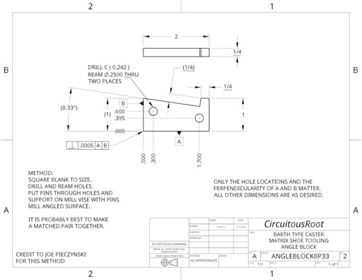
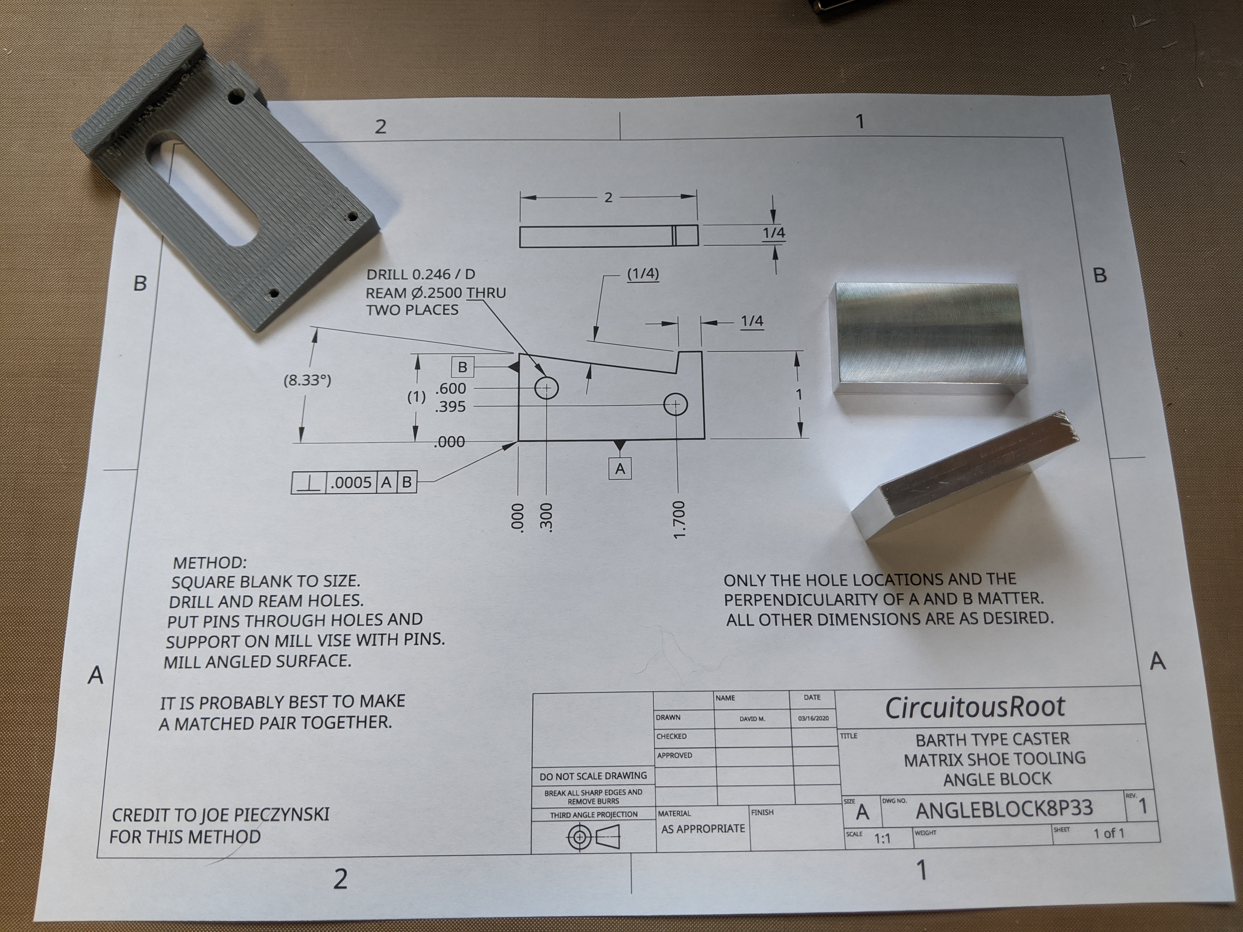
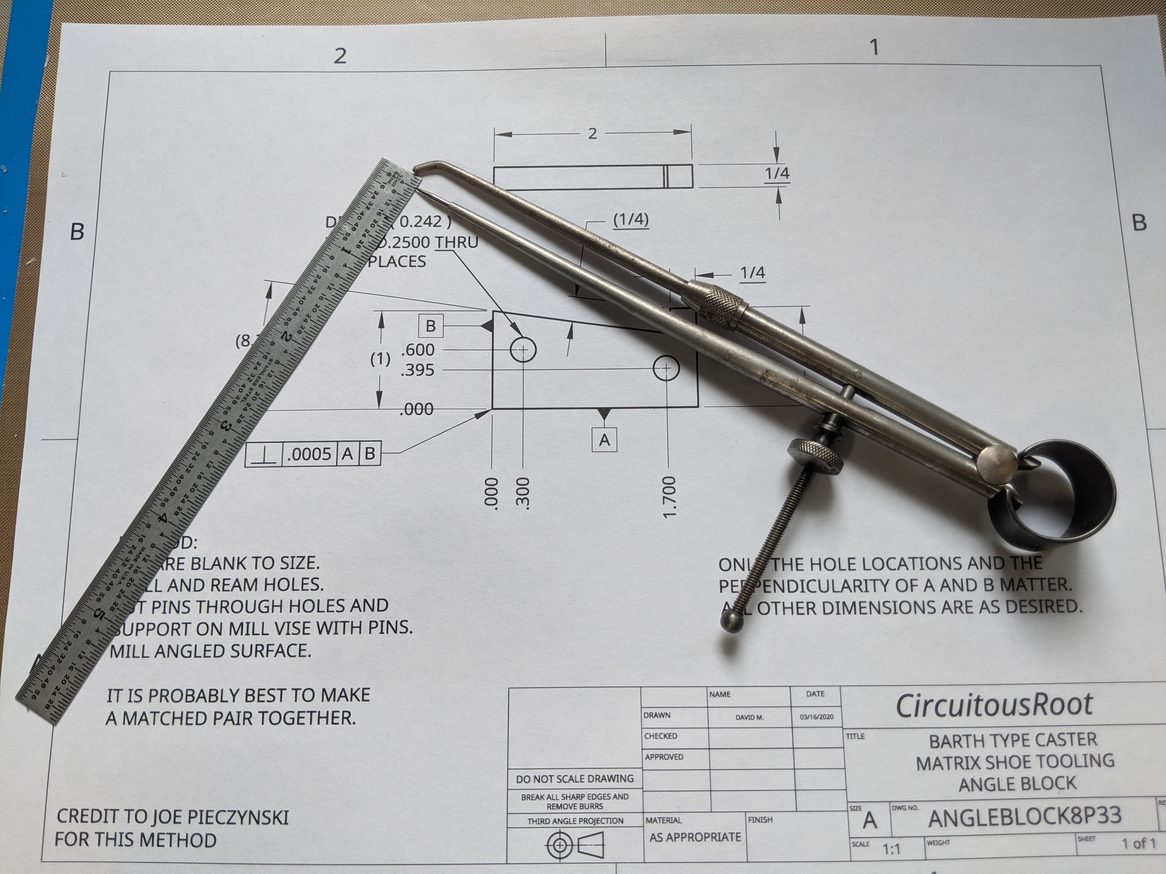
Here's the drawing (click or right-click for a PDF). As noted on the drawing, the only things which must be specified and made accurately are two of the sides and the positions of the holes. Every other dimension and feature may be as convenient (in fact, on the angle blocks that I made most of these other dimensions differ from the drawing by 1/8 inch or more).
(Dimension the holes from the bottom and just one of the sides. Do not dimension the two holes from both sides. This lets you avoid having to control the length of the part accurately.)
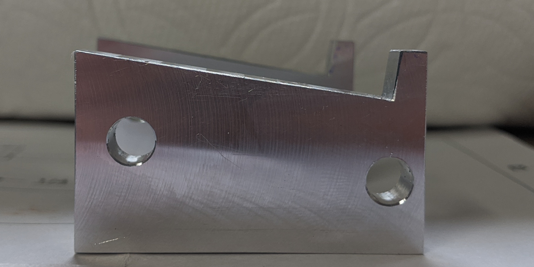
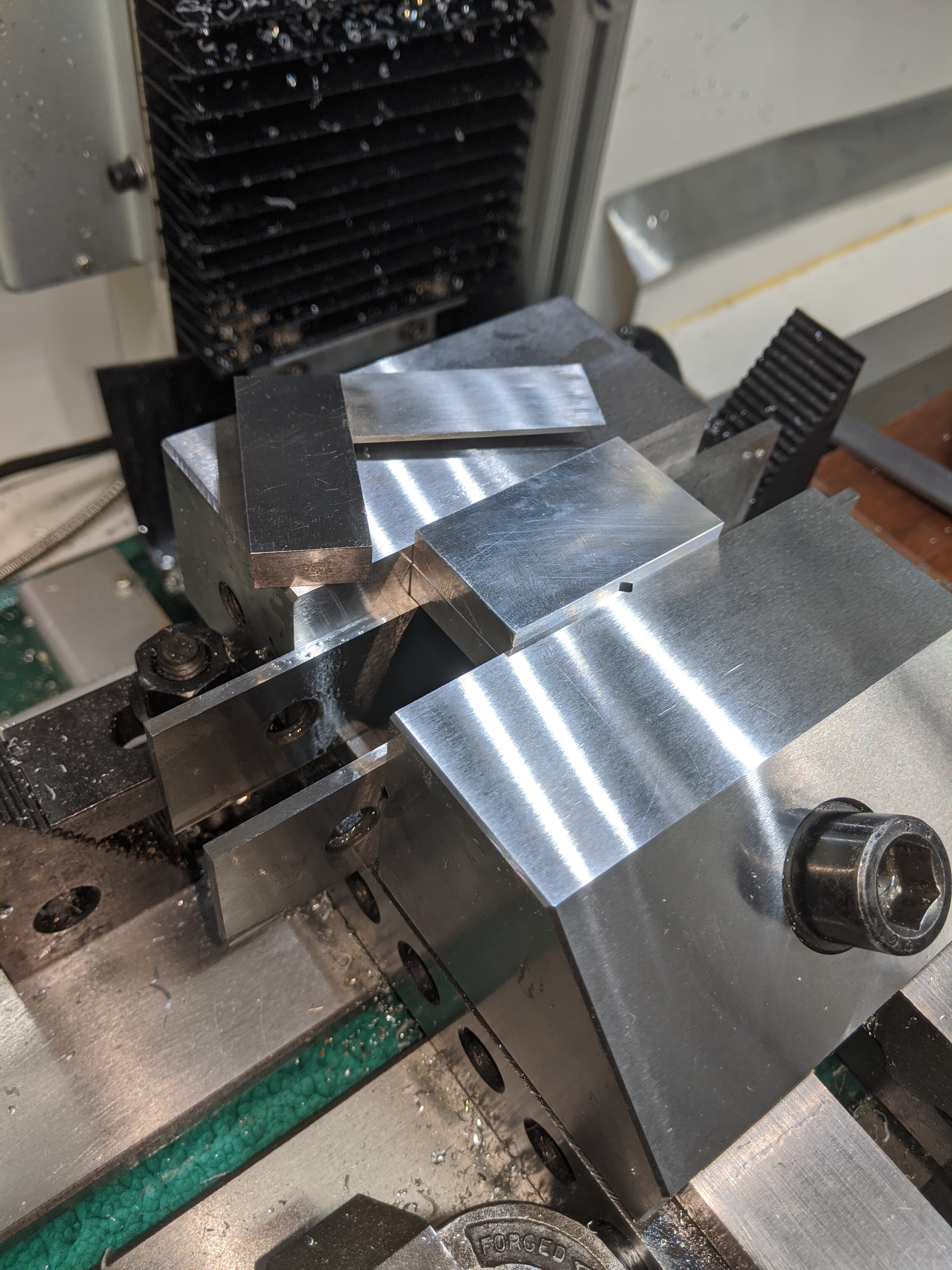
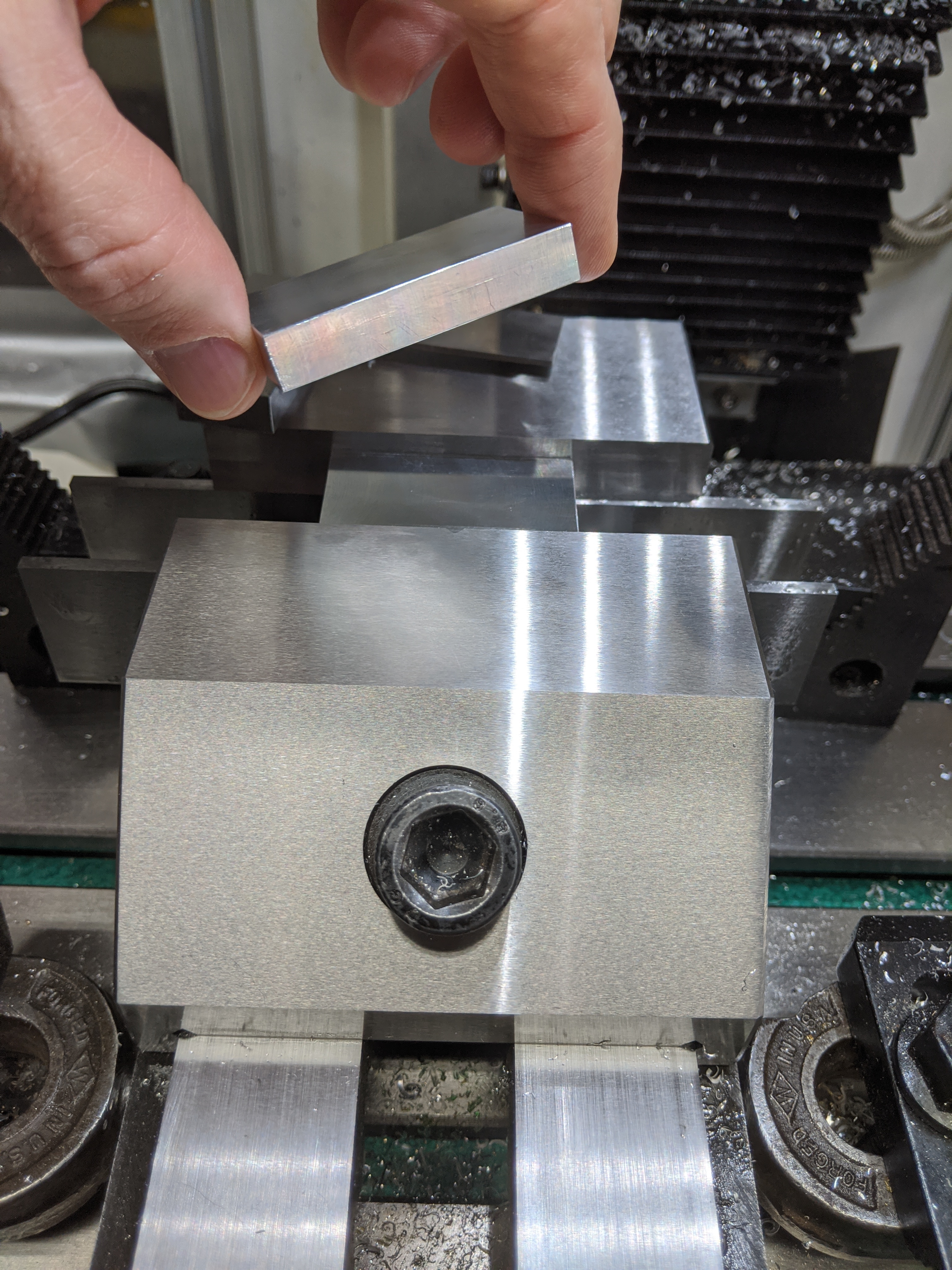
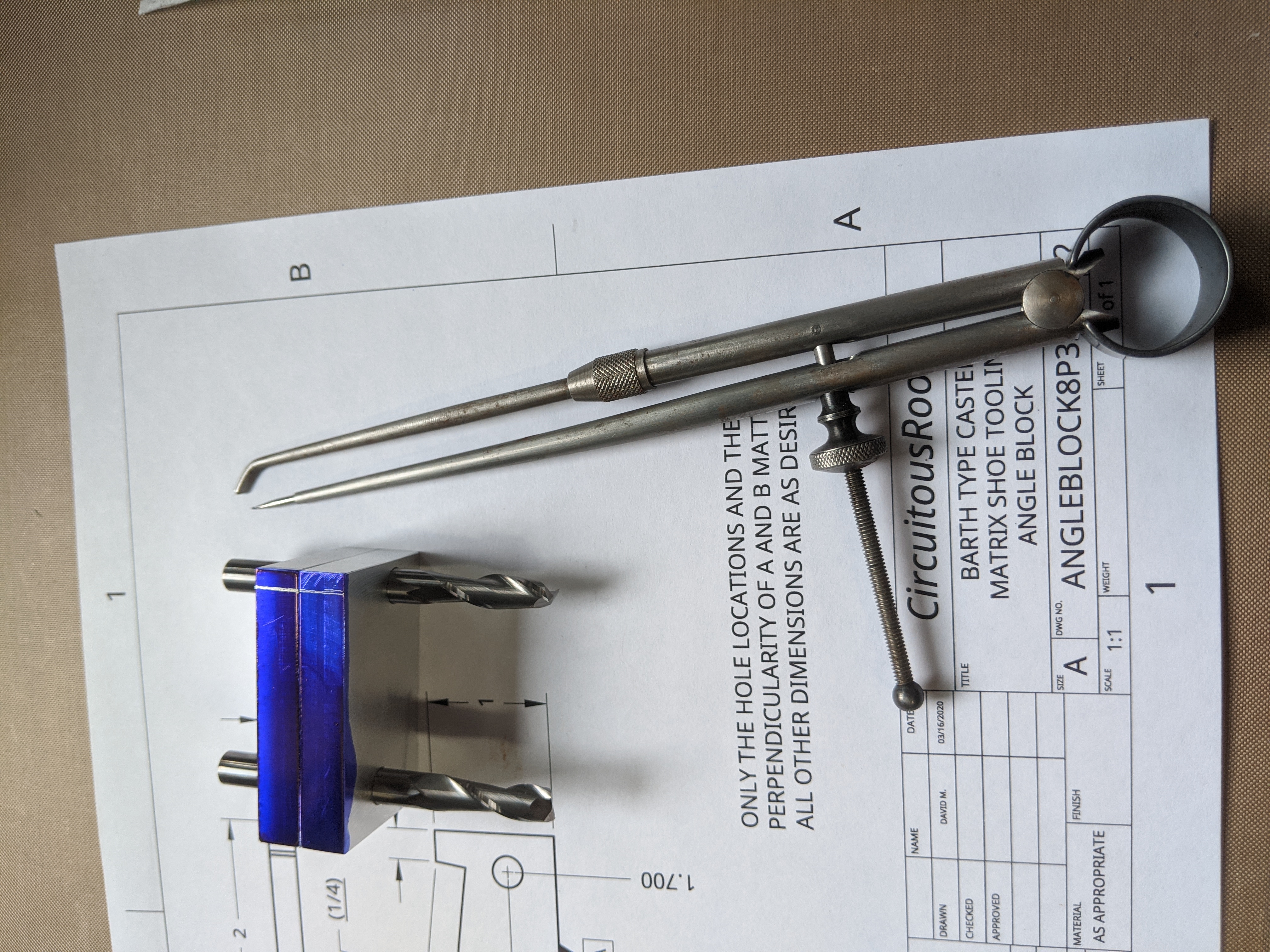
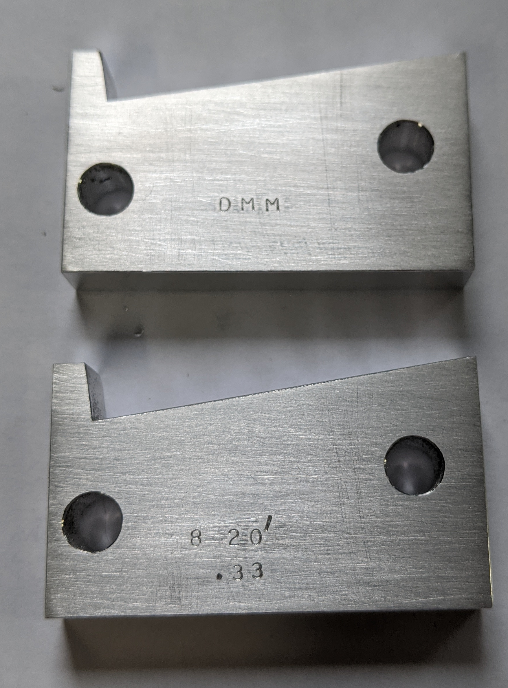
Here is a completed pair of blocks (it's always best to make a set). The material is aluminum (6061-T6, but that's just what was handy). Aluminum is fine for these because they'll never see much wear. If you were making them for production you'd use steel. If you were making them for sale you'd grind them out of hardened steel. (But the world market for 8° 20′ angle blocks for making Barth type caster parts is . . . one.)
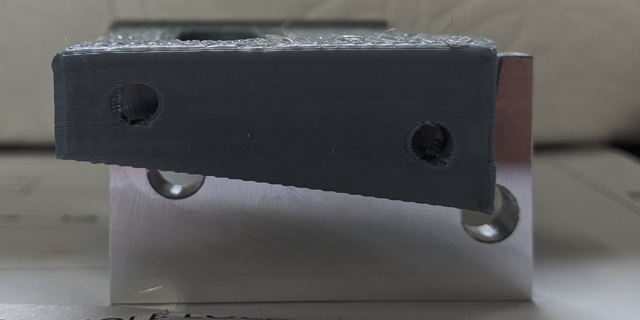
Here they are in "simulated use" with a 3-D printed mock-up of the Barth Matrix Shoe.
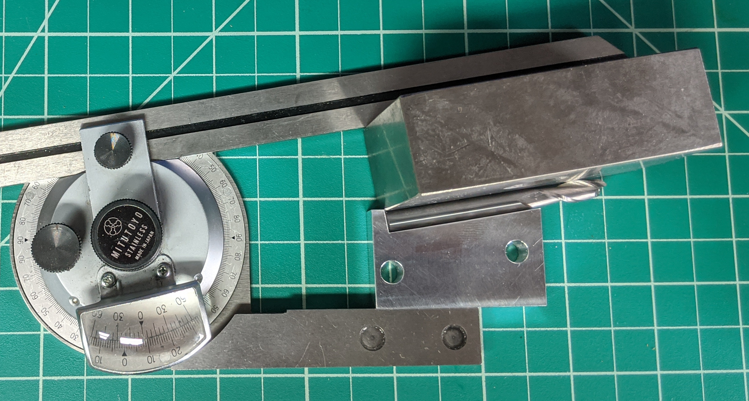
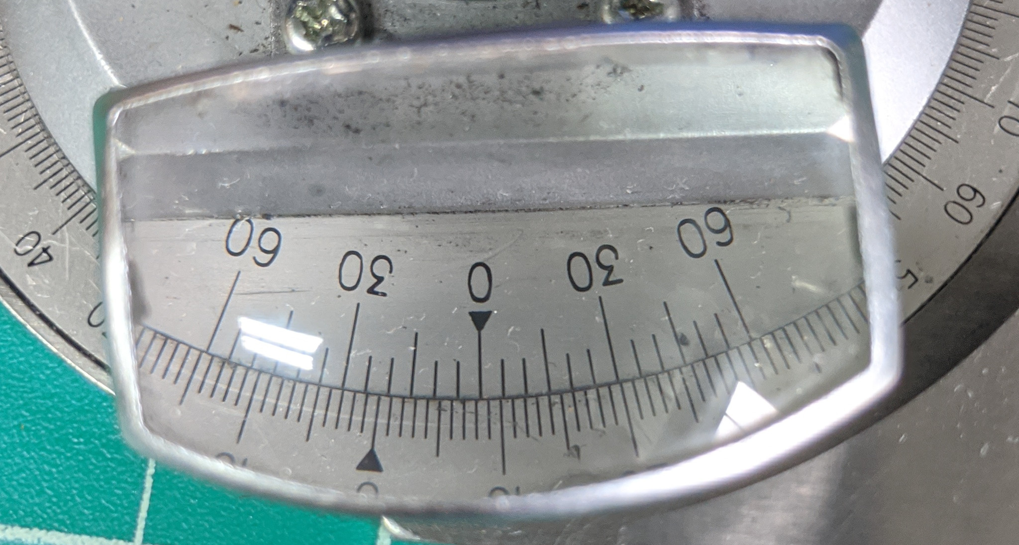
How accurate are they? Within the limits of my Mitutoyo vernier protractor, they're spot-on at 8° 20′ (which is 8.33°). The G0759 mill on which I made these struggles to hold a thou. A method which allows you to make an angle to +/- 2 1/2 arcseconds on such a mill isn't half bad.
None of the actual machining steps involved anything out of the ordinary. This is simple work well within the capabilities of any beginning machinist (even me!) Here are some miscellaneous photos of the process.
Even though I milled both of these parts to size together in a single operation, it still isn't a good idea to stack them in the vise to drill both at the same time. As near as I can tell with a Mitutoyo 1-2" micrometer, the widths of the parts are 1.102,5" and 1.102,7" (only 2 tenths difference). Yet with both clamped firmly in the vise, one on top of the other, I can lift the top part out with my fingers. It's a pretty rigid vise.
It's better to set up a workstop. This allows you to find the left edge, zero the DRO in X, and then cut both parts without re-finding the edge. If you set things up so that you locate Y=0 at the fixed jaw of the vise, you don't have to re-find any edge for the second part.
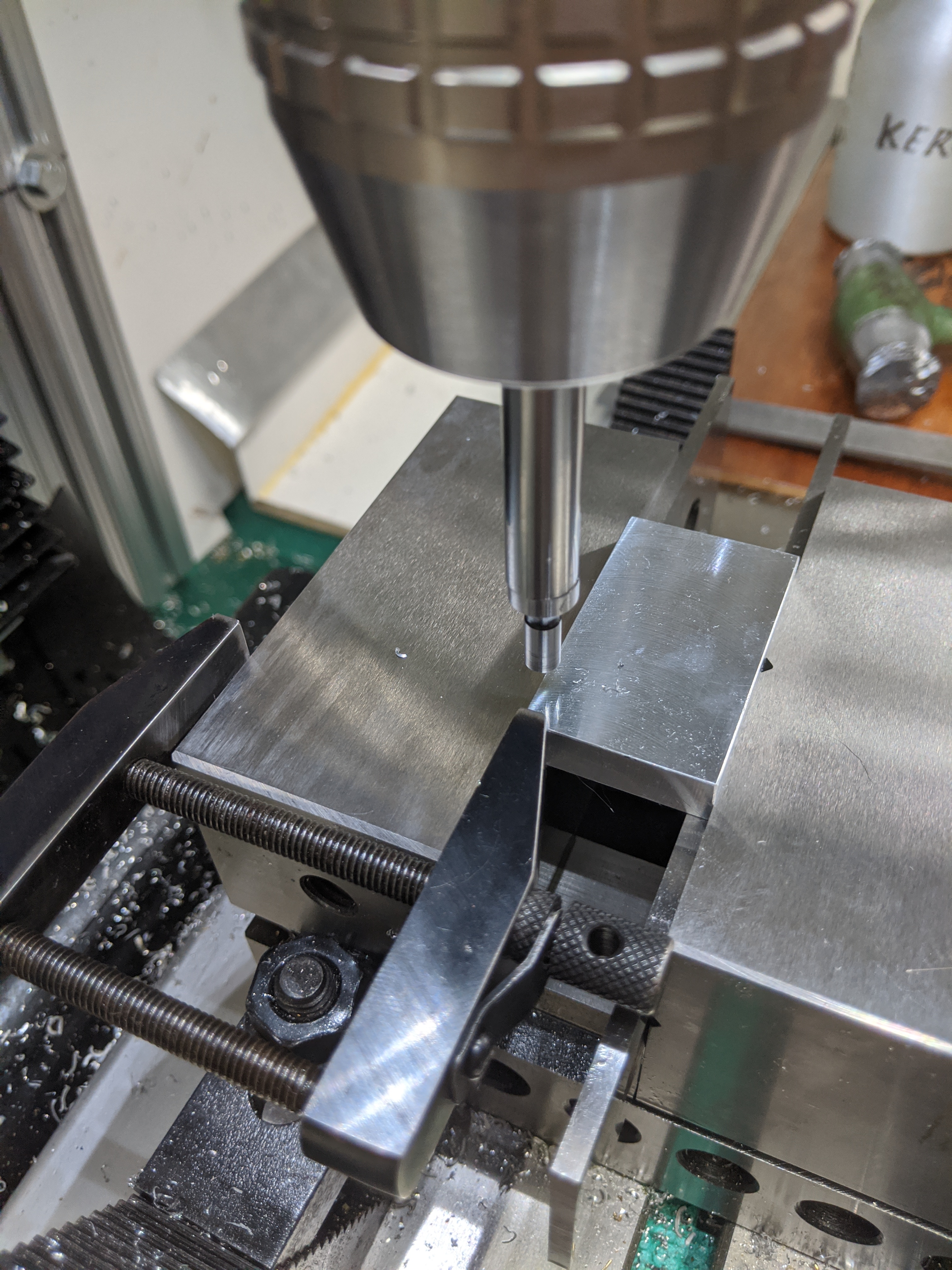
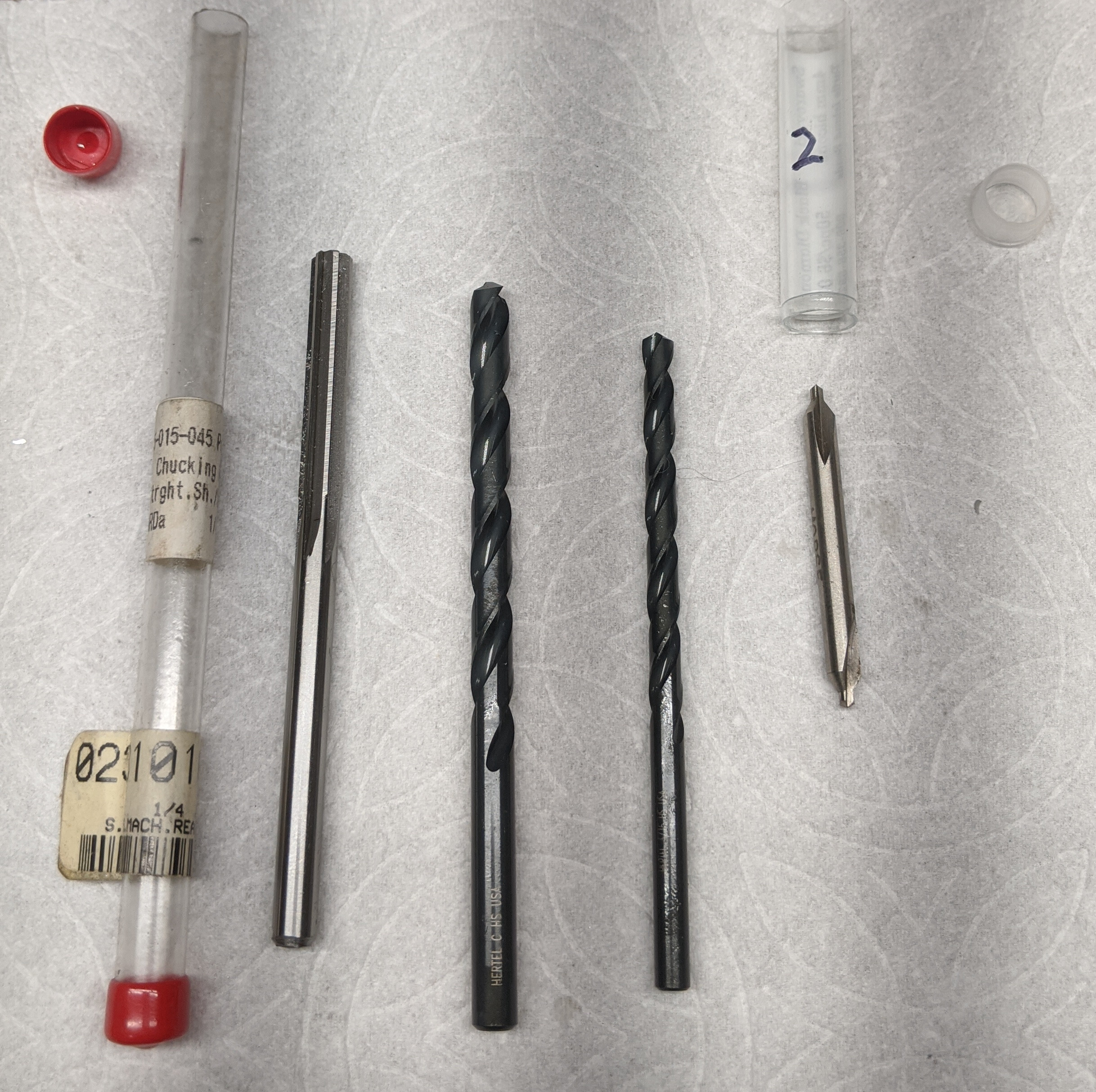
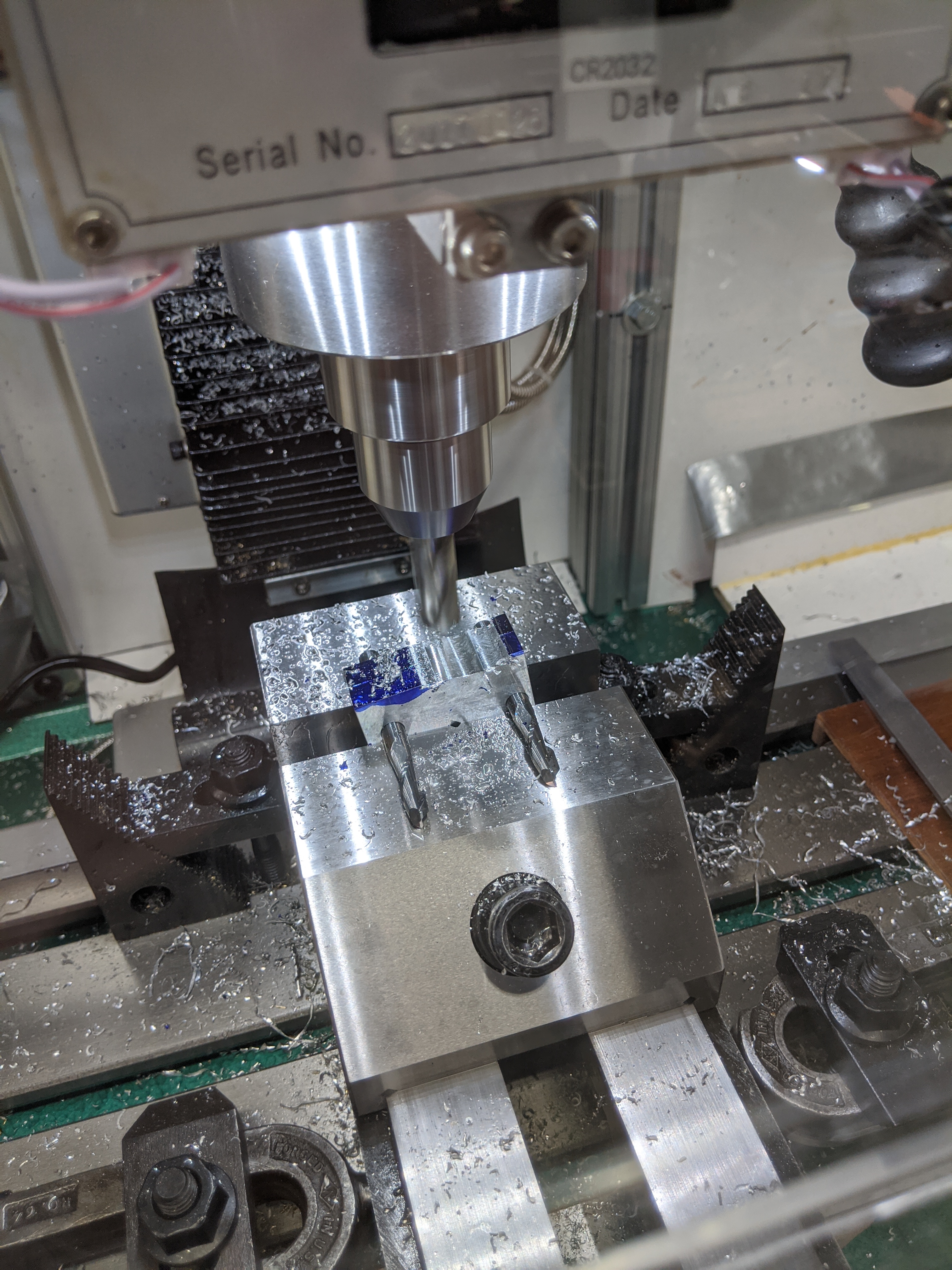
Then just centerdrill, drill to clear stock, drill to specified undersize, and ream to size, as usual. Deburr.
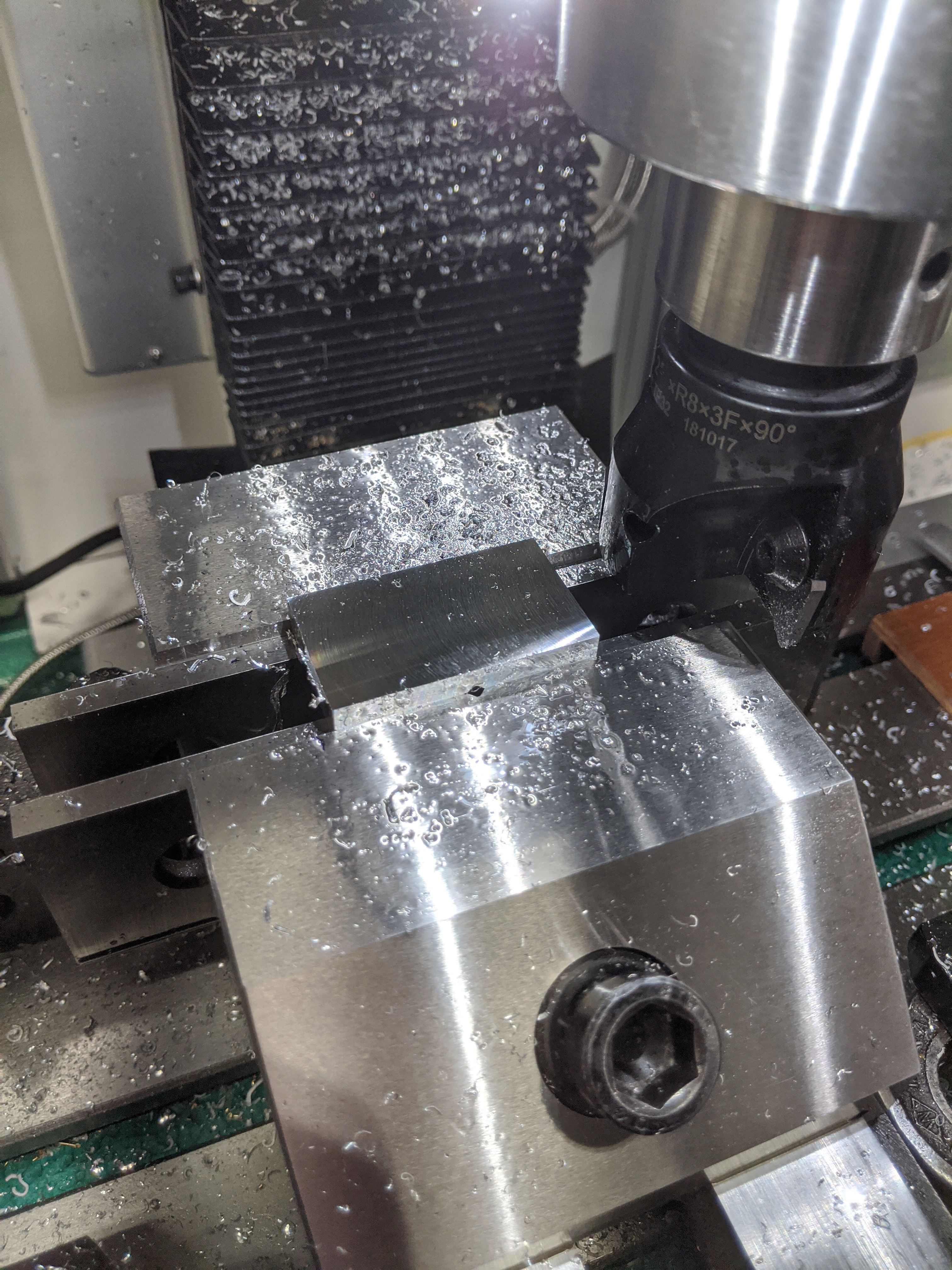
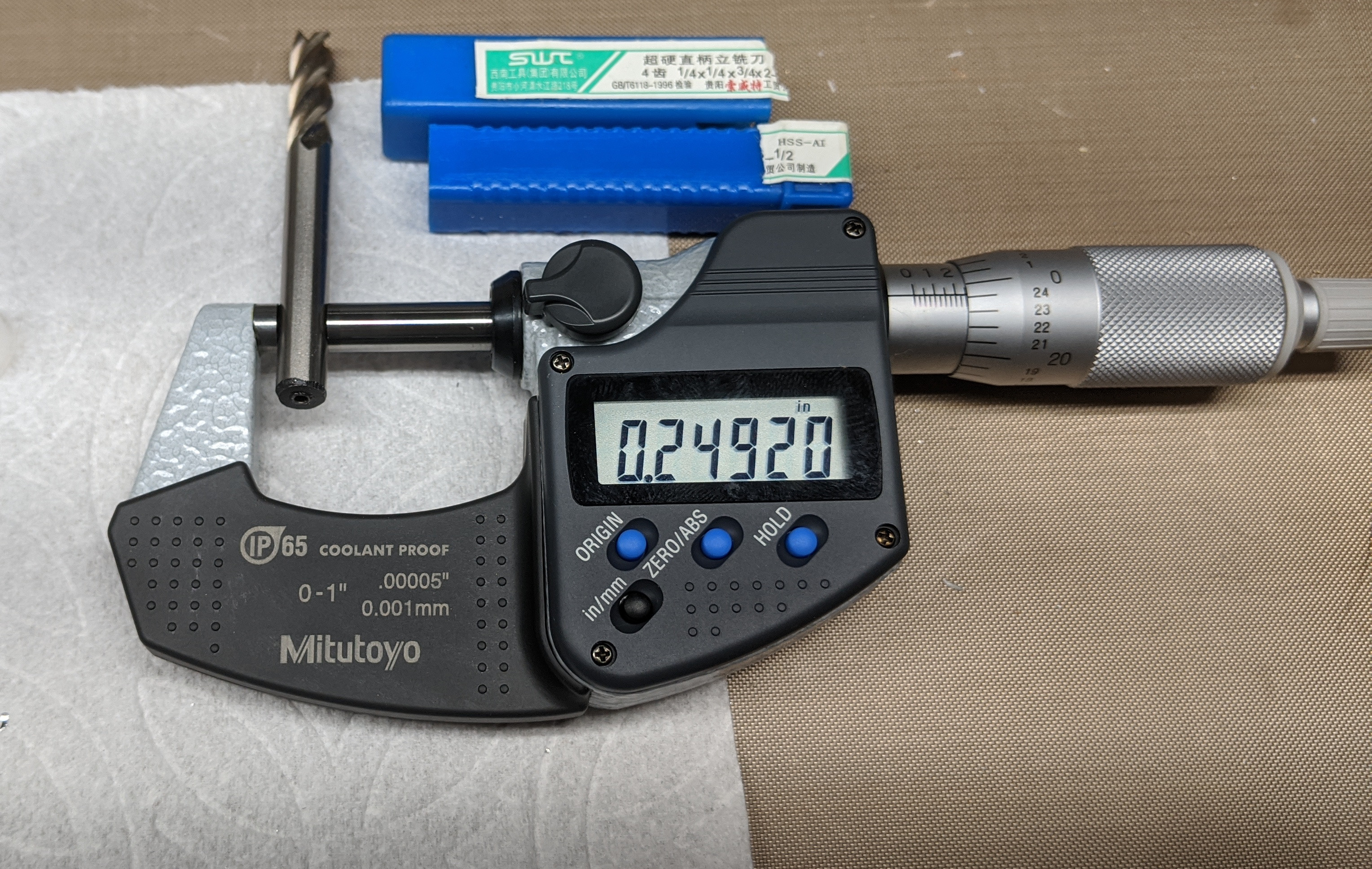
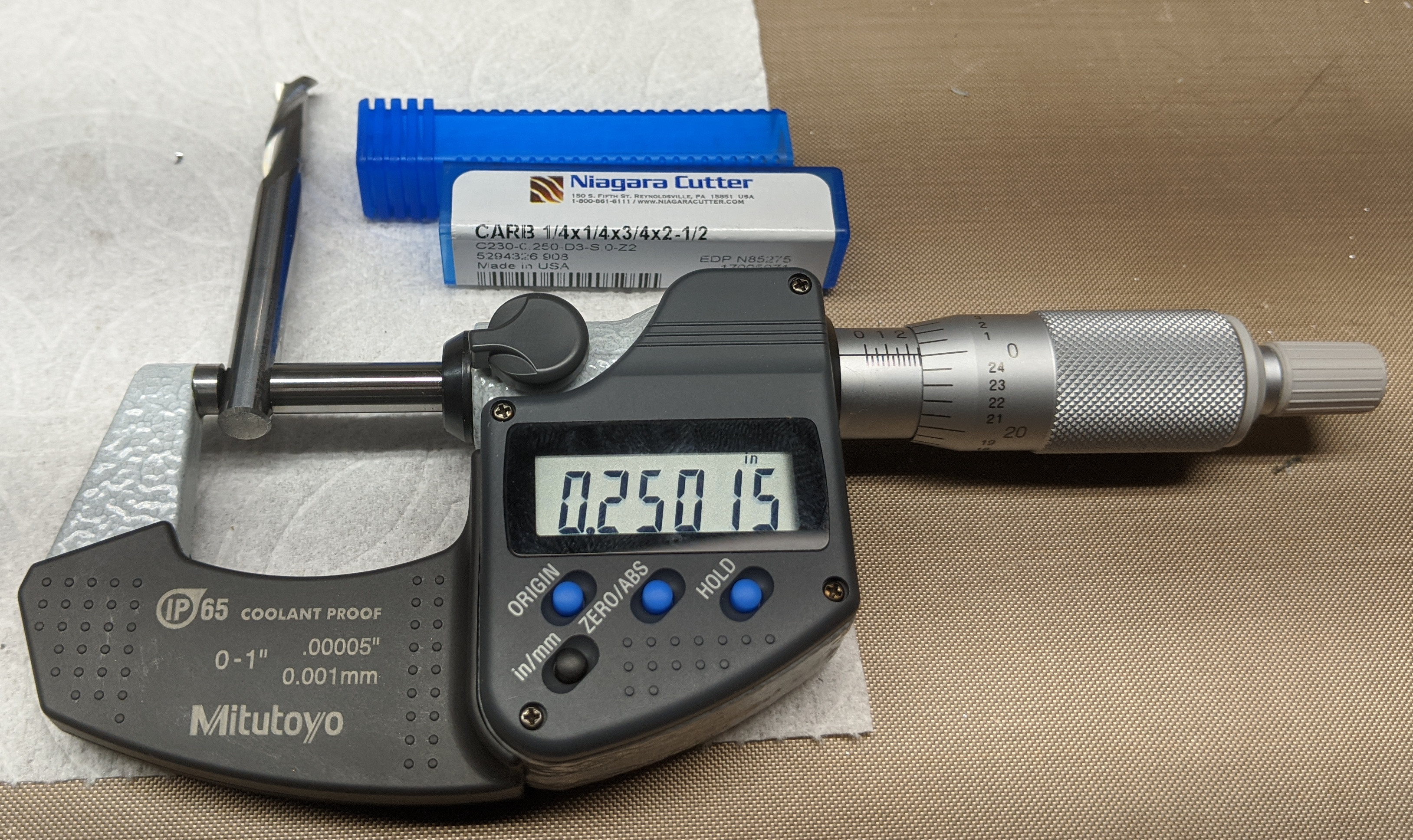
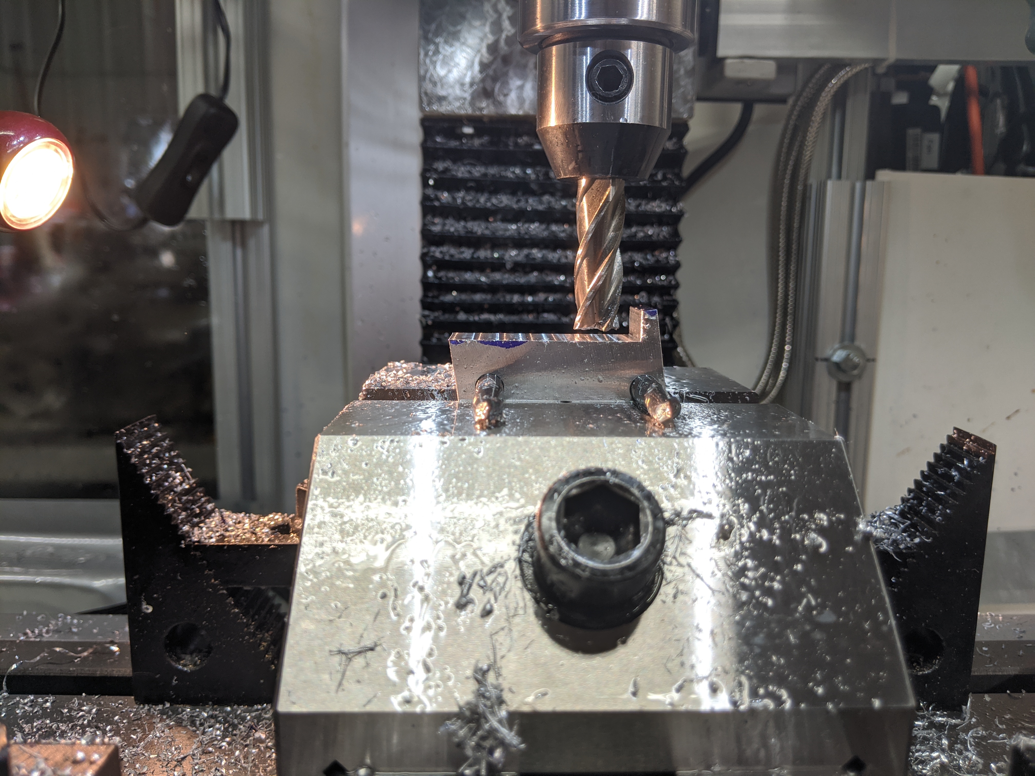
In theory, you would use gage pins through the holes, to locate the blocks against the top of the vise. But that takes two sets of gage pins, and in any case I didn't want to put the extra wear on them. Generally, end mill shanks are really close to nominal diameter and they make excellent substitutes. But all end mills aren't quite the same. Below, left, is a less expensive end mill clocking in at 0.249,20 (Mitutoyo digital micrometers are, in modern debased language, awesome.) This end mill is perfectly suitable for the purpose for which it was sold (being an end mill). At 0.000,80 undersize, it isn't bad. But below right is a Niagara brand end mill at 0.250,15. At 0.000,15 oversize, these are the ones I'll be using.
The "hook" feature on the top of the block is optional. Sometimes it helps, but in other situations it might be in the way. It doesn't really matter how big it is. The drawing calls out 1/4", but I just made that up. In practice, since my block ended up about 0.1" short, I decided to make it 1/8". This dimension doesn't have to be accurate. I used semiprecision layout to scribe it and then just came up close to the line by eye on the mill.
The method of scribing is insufficiently well known. All layout is semi-precision. For the most precise semi-precision, you'd use a height gage on a surface plate. Don't need that here. For this kind of thing, many people just use the tips of their 6"/150mm calipers. There is absolutely nothing wrong with that - so long as they're Harbor Freight calipers. (You're not going to find me doing this with my Mitutoyo calipers!) But if people give you grief about this, there is an alternative: hermaphrodite calipers. Any style of hermaphrodite caliper will work; slip-joint versions are the most common. My own preference is for these long-discontinued Craftsman (brand) calipers. They have a nice screw adjustment and a replaceable bent-tip.
(The fact that this is a pretty crappy layout job (below, right) is independent of the quality of the calipers. I shouldn't have just tried to hold it all freehand. It doesn't matter, because I could have eyeballed it all on the mill, but it doesn't look nice.)
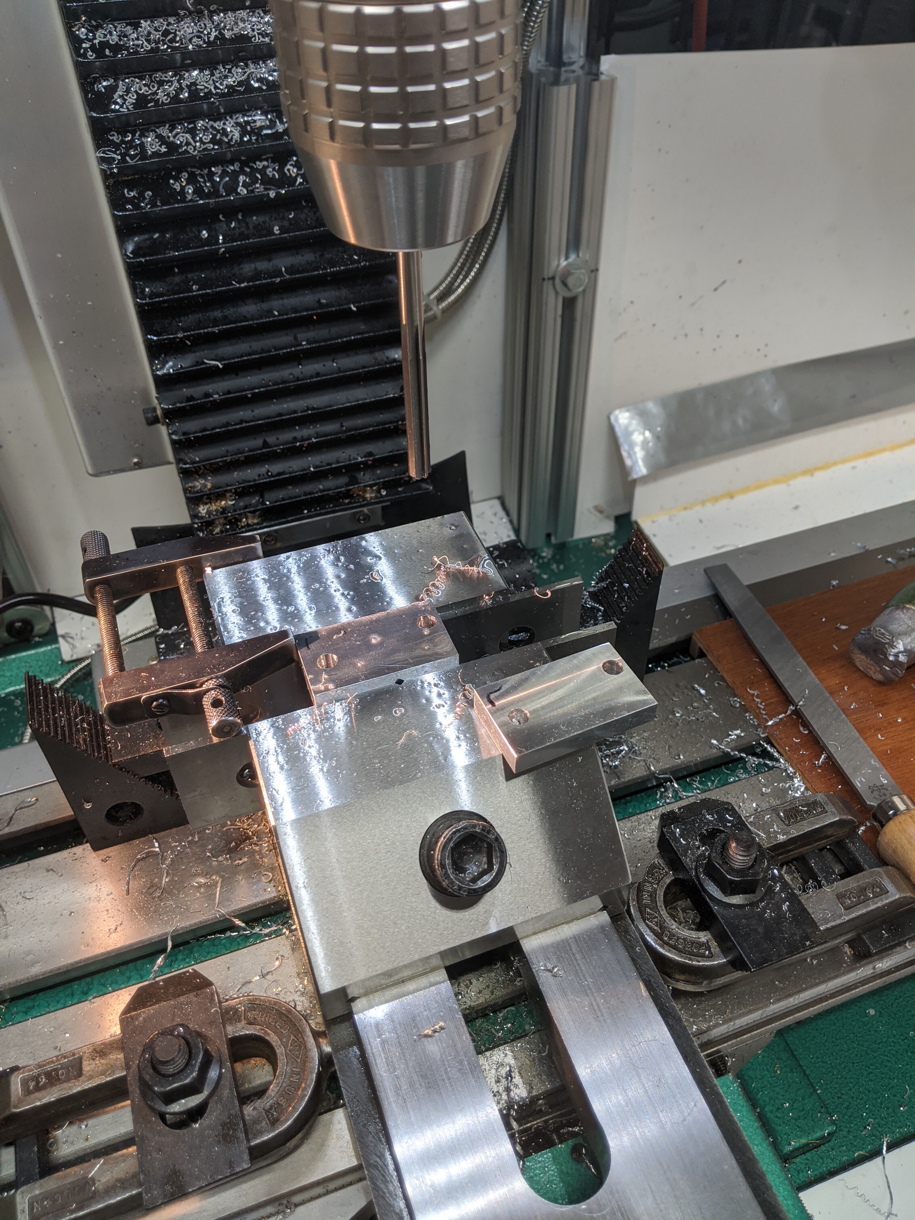
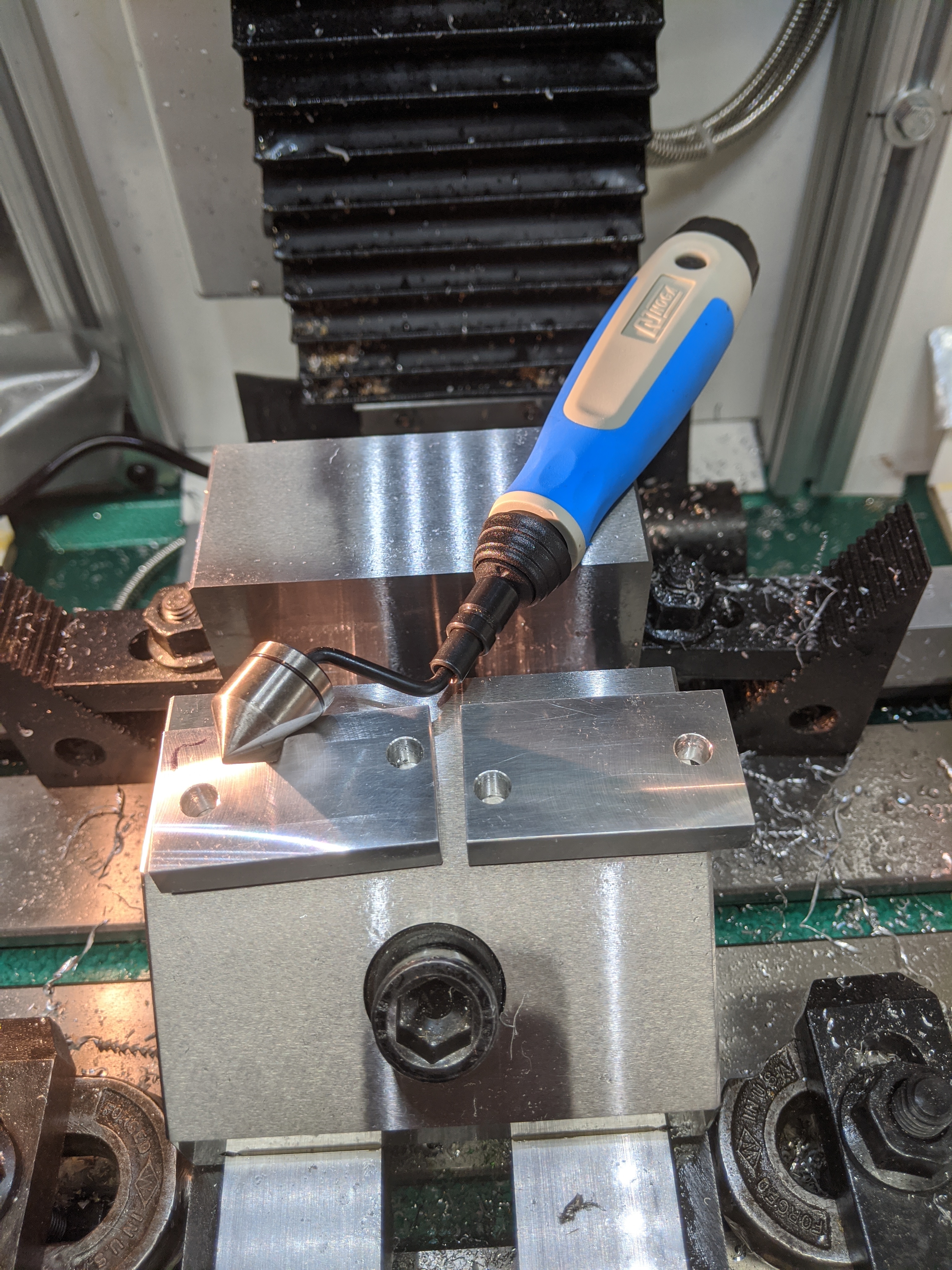
Here's where the magic happens.
Marked, as crudely as any teenager's shop project from 1950. I really need to go further back and learn 18th century engraving.
All portions of this document not noted otherwise are Copyright © 2020, 2022 by David M. MacMillan.
Circuitous Root is a Registered Trademark of David M. MacMillan.
This work is licensed under the Creative Commons "Attribution - ShareAlike" license, version 4.0 International. See http://creativecommons.org/licenses/by-sa/4.0/ for its terms.
Presented originally by Circuitous Root®