I should be clear at the outset that this project is just an experiment. It's not even a prototype yet. It's something lashed together to see what does and doesn't work. It's ugly.
This writeup will of course be too long. That's partly because I like writing. It's also because I'm writing this as I'm building the project. The first part of this writeup is really a design requirements document.
Oh, and this mill enclosure is being cobbled together out of materials on hand during a lockdown in the 2020 coronavirus pandemic. This is not engineering, it is bricolage.
It's actually very hard to find pictures of old machine shop floors in need of sweeping. Turns out most people tidy things up for the photographer - and I'm not going to take a picture of my own shop floor as an example!
If you're just working at a small milling machine using small end mills and cutting without a flood coolant system, handling the chips it produces isn't difficult. They don't go very far and you can deflect them as needed with small movable polycarbonate screens (neodymium magnets are very useful here). This is no different than the traditional method of using any mill: the mill makes chips, the chips fall on the floor, and you sweep up the floor at the end of the day/shift. The floor can get pretty "crunchy" during the day, but that's just a part of a traditional shop.
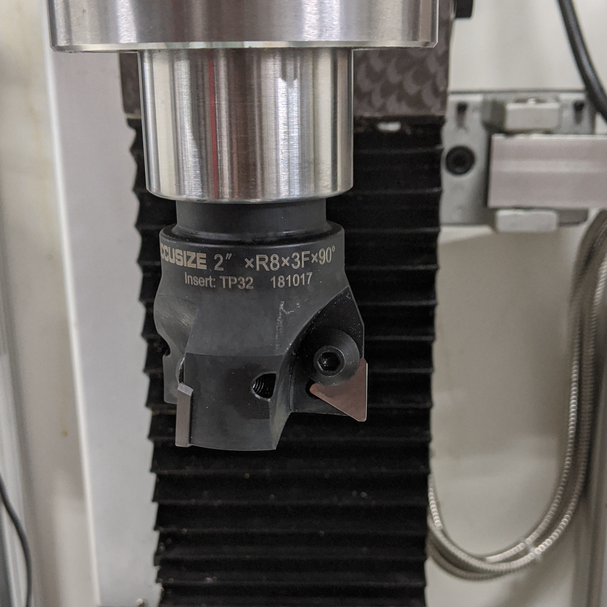
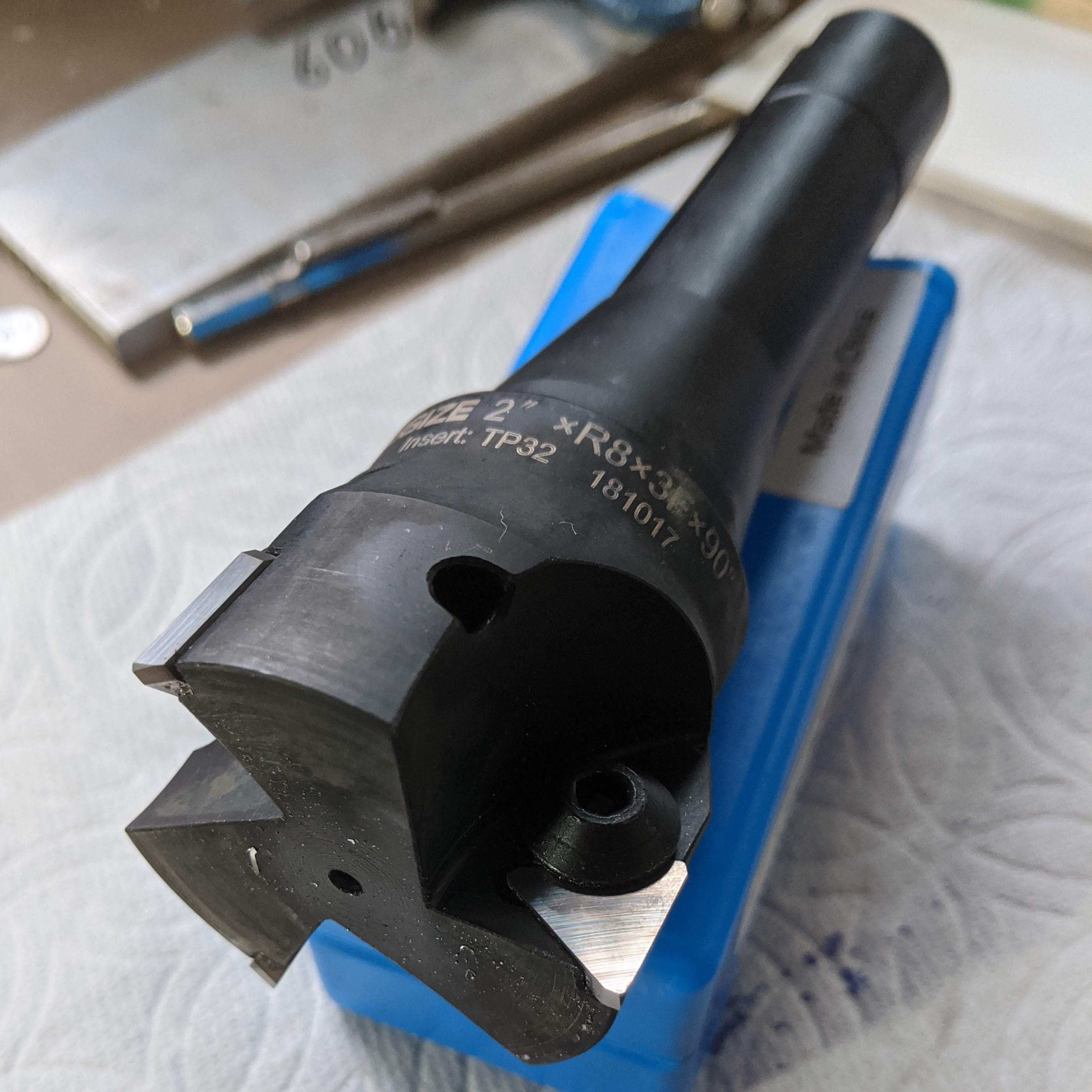
Until a couple of weeks ago, this is what I was doing. But then I tried using a larger carbide-insert face mill. It worked very well, but boy did it shoot chips all over the shop. A flycutter would do the same. As those of you who have seen my house know, I'm not a particularly tidy person, but this exceeded even my comfort level for workshop orderliness. I am also worried because my former barn cat, Simone, is getting up in years and has now become my machine shop cat - and Simone can't wear shoes.
The solution is obviously an enclosure of some kind.
Most of you aren't really interested in a long discussion of the process, so even though I detest the very concept of TL;DR (because it valorizes ignorance) here's the result. It's ugly, but so far it is working surprisingly well. More importantly, it is enabling me to figure out what a better version would be like.
The rest of this posting will be of little interest to most people (note to friends: you can stop reading now and I won't care). It's a fairly detailed study of the requirements for this project, the approach taken, the problems with that approach, and changes envisioned for Version 2. In other words, these are just my notes - I'm storing them online so I won't forget where I put them.
Milling machine enclosures are not unusual. Indeed, in serious new machines they're simply a part of the machine. Any real CNC machining/milling center ("real" meaning purpose-designed as a CNC machine, as opposed to a CNC retrofit of a manual mill by an individual or a vendor) has the enclosure designed as a necessary part of the mill. But the requirements for my enclosure are slightly different because I need an an enclosure for a manual mill. Though I didn't search exhaustively, I was unable to find any designs (for reference or guidance) for enclosures for manual milling machines. (I did, though, find several designs which had very good ideas. Some of these ideas I borrowed, some I did not.)
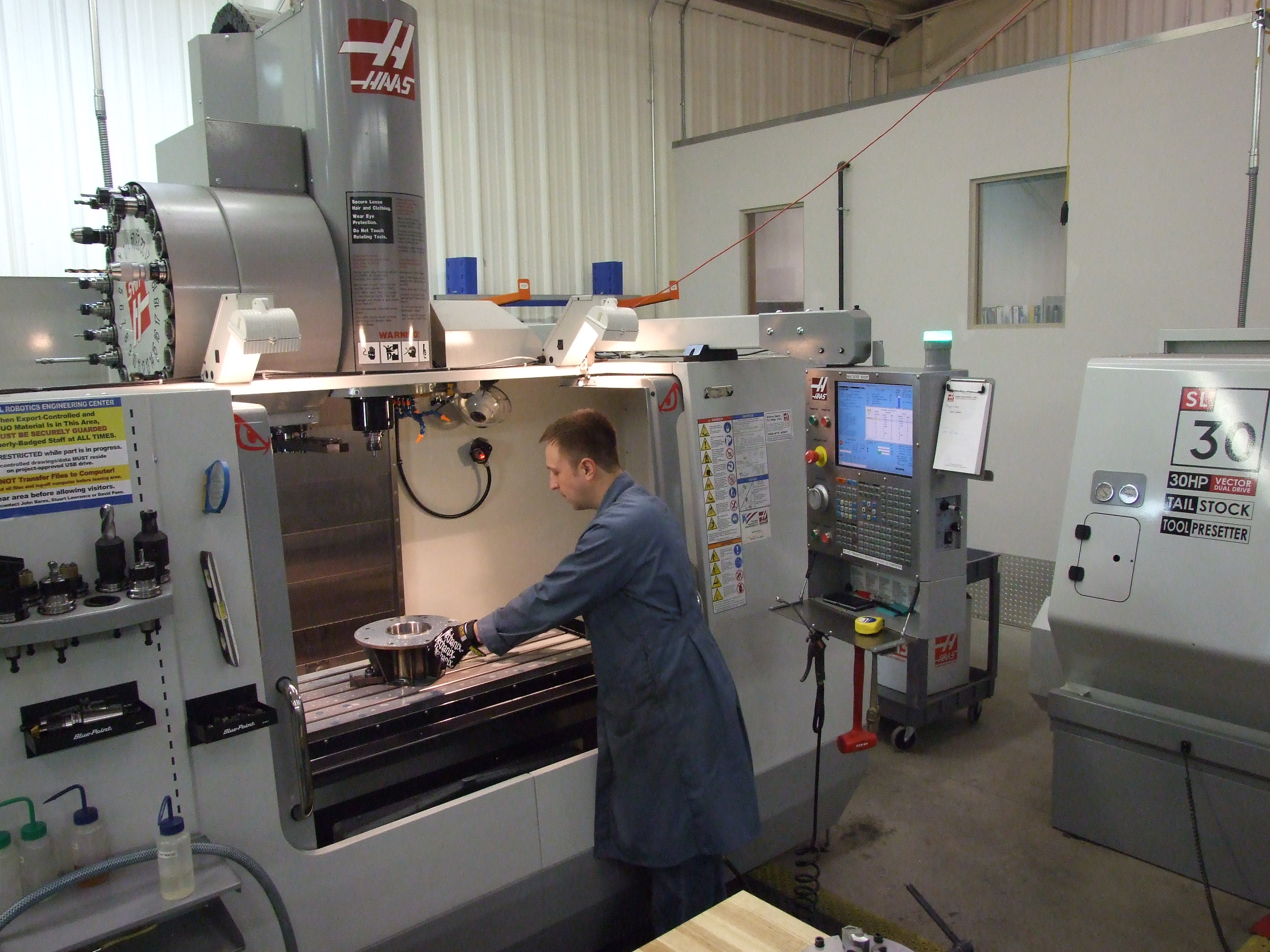
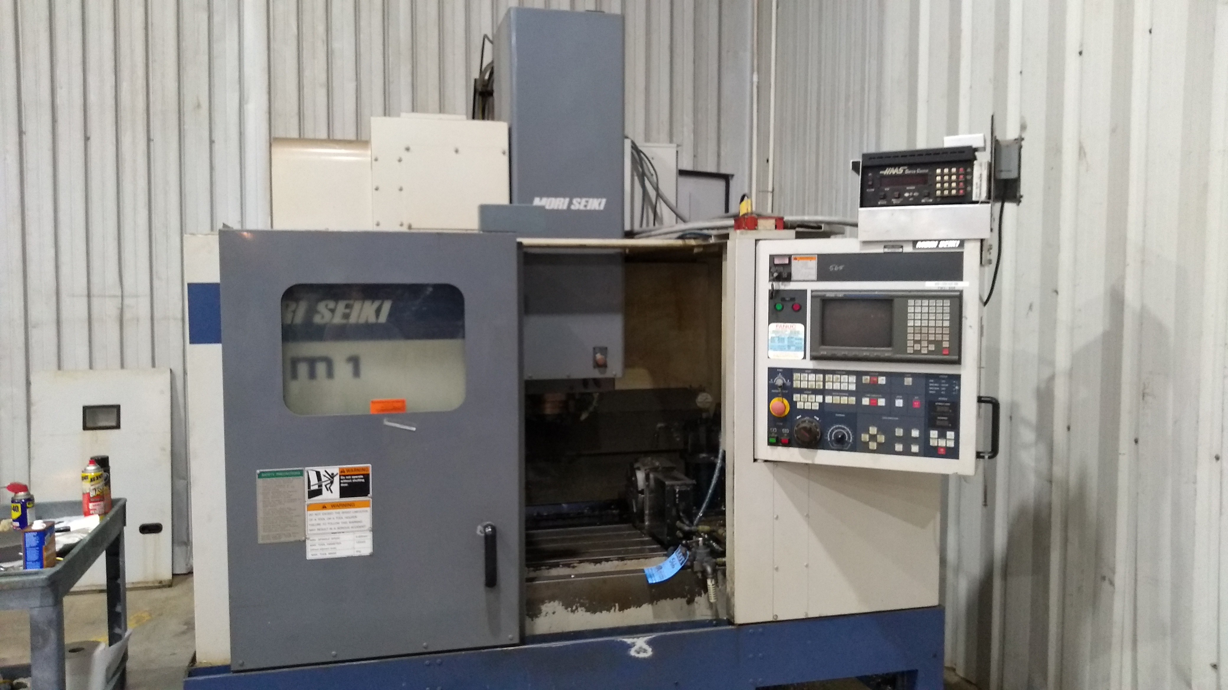
So for reference to "real" practice, here are two photographs of mainstream CNC milling machines (not ones in my shop, unfortunately):
(Above left: A Haas Automation, Inc. Vertical Milling Machine (model unknown; it might be one of their VF series) at the National Robotics Engineering Center of Carnegie Mellon University. Note the tool changer (the drum-like unit on top). Above right: A 1997 Mori Seiki (now DMG Mori Seiki Co., Ltd.) FM-1 Vertical Machining Center. For sources and credits for these and other photographs on this page not taken by me, see the Legal Notices box at the end of the page.)
Typically, CNC milling machine enclosures are just big boxes completely surrounding the machine, with a door in the front through which the operator loads the part. In operation, the doors are closed and all control and measurement interaction happens via the computer or the control panel outside of the machine. The machine and its doors are usually interlocked for safety - the machine will not run at working speed with the doors open. (Some may allow low-speed operations with the doors open. This can be useful during setup.) Further, a real CNC mill often has a tool changer (again, reducing operator interaction because all tools are pre-loaded in the tool changer) and flood coolant. All of these things are great, but they're not my situation.
(I'd like to think of this as an insight, but really it's just an opinion.)
There are many home machinists who have done CNC retrofits of manual milling machines. This is great, and indeed I plan to do the same someday with this mill. You can now buy the same in the US$5k and up price range. The next step up brings you to several vendors who produce quite attractive machines in the roughly $10-20k range. These are sold as pure CNC machines, but really they're still retrofits onto what were originally manual mill designs. But a purpose-built CNC machine starts at maybe $50k (for a bare machine). Prices go up very rapidly from there. Why are they so expensive?
A manual mill is run by a machinist, who can see and compensate for any errors. A CNC mill is run by an operator - a parts-loader. The "machinist" is a G-code programmer who might not even be on-site (or the machinist is no longer human - just a CAM program run on the computer of some engineer who has never seen the inside of a machine shop). Everything must be expressable in the G-code without a human to compensate. This means that a real CNC machine must have unthinking repeatability. There's a lot more to this than just throwing ballscrews at a manual mill design. Building this repeatability into a machine costs serious money.
Enclosure Requirements for My Manual Mill
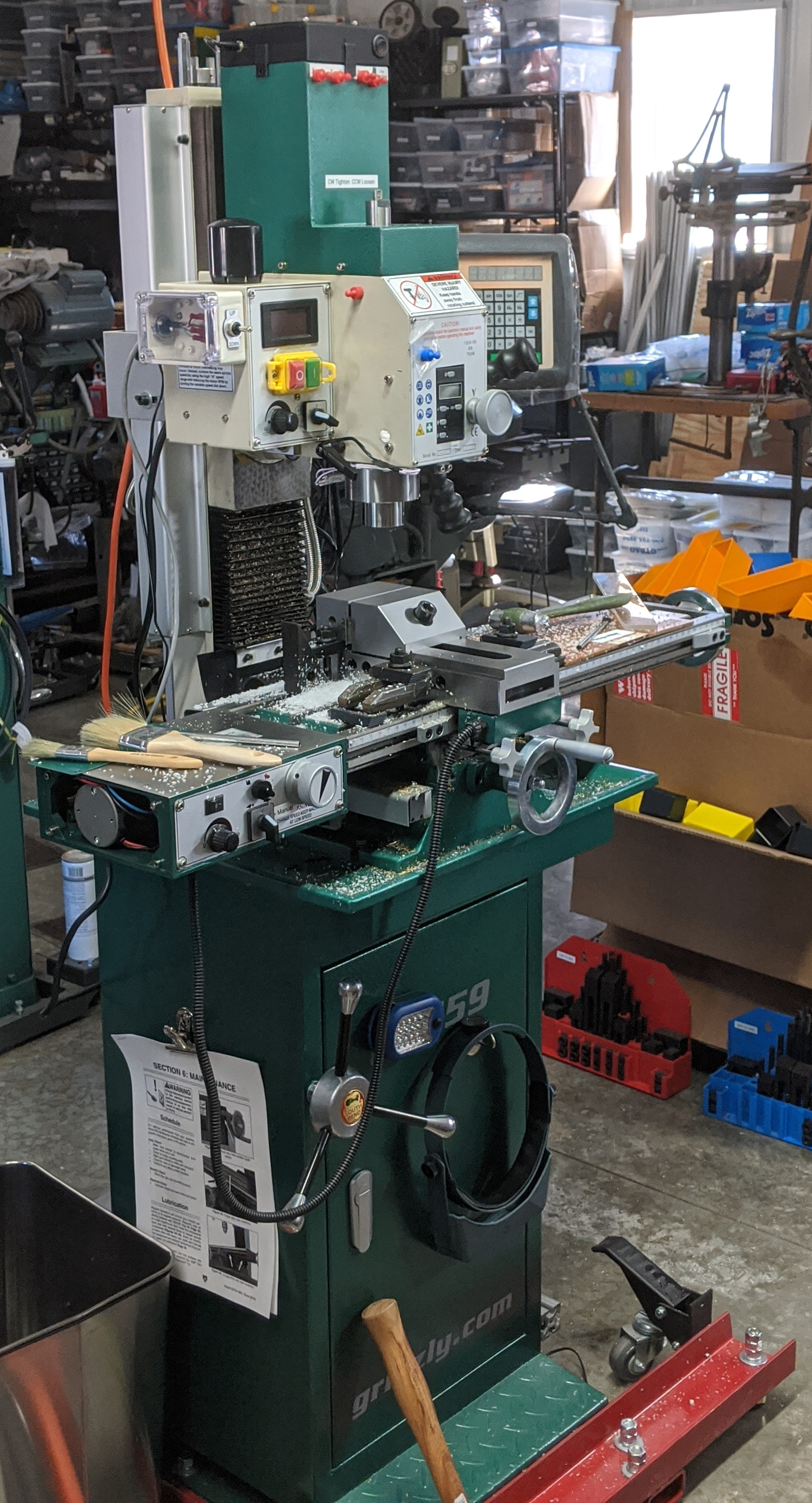
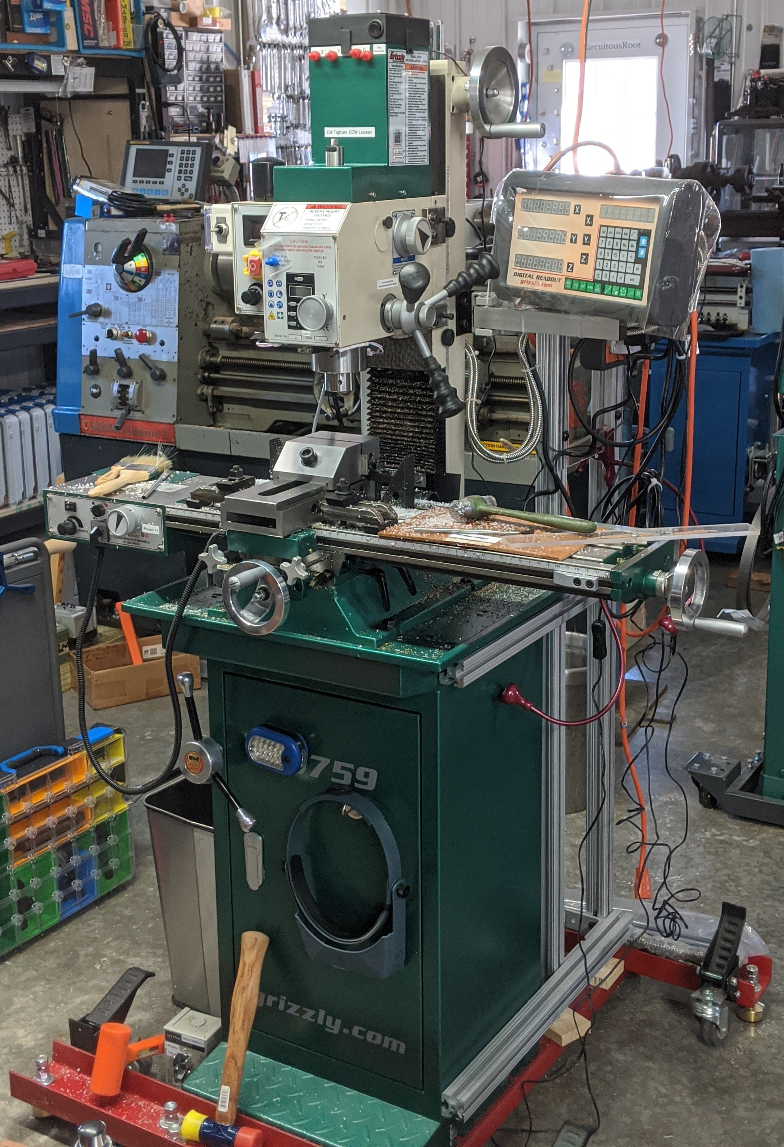
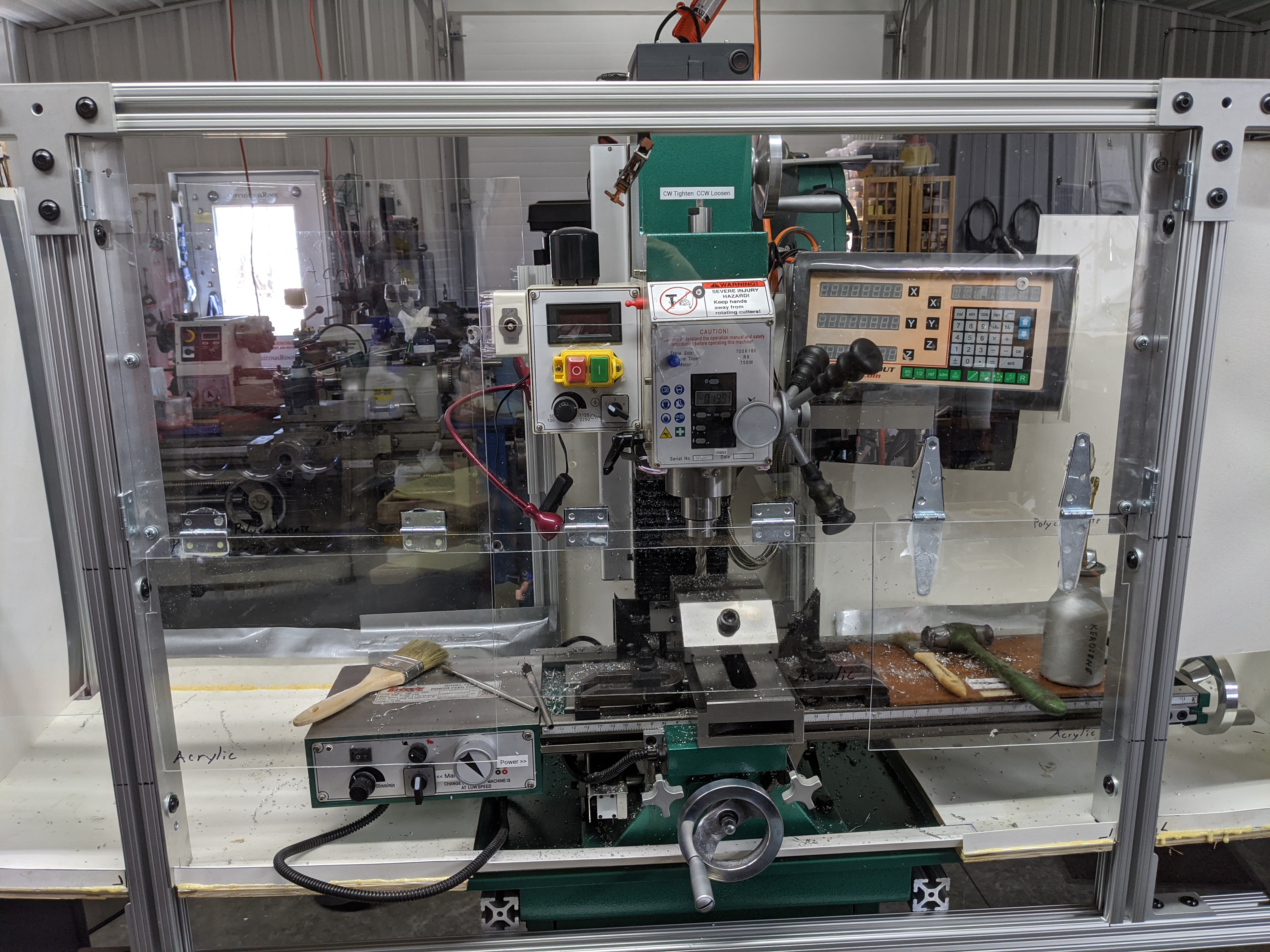
My manual mill, a Grizzly (brand) model G0759, is a benchtop mill (aka "mill-drill"), though mine is mounted on a stand rather than a bench. It's Grizzly's version of the ubiquitous "BF20" design made by many factories in Asia and available from many vendors. It is equipped with a Digital Readout (DRO) and X-axis power feed. (A G0759 is just the popular Grizzly G0704 mill with a factory-installed DRO. I installed the Grizzly T23010 Power Feed for the X-axis myself.)
Here it is, before the enclosure. Things may be a bit messy - but the floor is swept! And, yes, I'm using a large toolmaker's vise rather than a regular milling vise. This is what comes of watching too many of Stefan Gotteswinter's videos on Youtube . (But this one doesn't have a proper side-slot. The clamps holding it to the table are disproportionately large because they're what I had and I haven't yet made proper ones.)
Building an enclosure for this mill (or any mill) should start with defining the different kinds of access I need. I'll distinguish five situations:
Requirements for Maintenance and Adjustment
If you think that a hobby-grade milling machine is just "plug and play," then you really shouldn't buy one. They aren't. This mill isn't. It is a fact of ownership that fairly regularly you are going to be tearing down and rebuilding aspects of it.
An enclosure which makes this difficult is obviously a problem. So a large, awkward single-piece construction, however well it might work during cutting, would render the machine useless the first time you had to tear down the head, or the column, or the table. As you will.
(In my research, I discovered that at least some later numerically controlled versions of the Deckel FP2 mill (Deckel FP2 NC in the 1980s, Deckel Maho FP2 NC in the 1990s) were furnished with a clever system of panels which folded down on three sides (front, left, right) for easy access. I didn't end up doing this, but really like the idea. Unfortunately, I cannot find any freely reproduceable photographs of this mill. You can see it, with this feature highlighted, in a page on CNC mill enclosures on the "CNC Cookbook" site at: http://s3.cnccookbook.com/CCMillEnclosure.html)
Requirements for Daily Service
The Z-axis leadscrew is lubricated via an access port in the back of the column. This shouldn't present a problem. The Y-axis leadscrew isn't properly accessible in the first place. The real solution to all of this is to retrofit the mill with a forced lubrication system. Noted G0704 hacker "Hoss" has done this and published descriptions of his system.
This may require more than just doors in the front (for cleaning, especially). Also, the table (X-axis) ways and leadscrew require hand lubrication with an oil can from below. Part of the reason for building this as an experimental rig is to see how difficult the presence of an extended chip tray relatively close to the underside of the table makes this.
A "setup" is a single placement of a part (or parts) in the machine together with all of the operations which are done upon it. It's more than just putting the part in the vise; it includes loading tools and establishing coordinates (X and/or Y, and usually Z). Establishing coordinates may require running the spindle (to use an edge finder, for example). I'll distinguish three kinds of things done within a single setup other than the cutting operations themselves:
(1) Requirements for Initial Setup:
During each initial setup process, I need access to:
In manual machining, you get "up close and personal" with the machine and part during setup. Opening and closing big doors or panels is acceptable for these operations. During setup, the machine may be run with the doors open for operations such as edge finding.
(2) Requirements for Changing Z Within a Setup:
During each change of the Z axis, I need:
On a real CNC machine, this wouldn't be a separate "setup" step. The mill would just move Z and do it (it probably wouldn't even stop the spindle or turn the coolant off).
On a hobby-grade manual mill such as this, sometimes you can do the same. Often, though, you cannot. There just isn't enough rigidity and repeatability in these machines. So if you want to be sure that you're doing accurate work (especially on the last cut, after a day of working on a single part) you stop the mill, measure the part in-place, and then move Z (compensating for the difference between measurement (= reality) and where you and the mill thought you were.
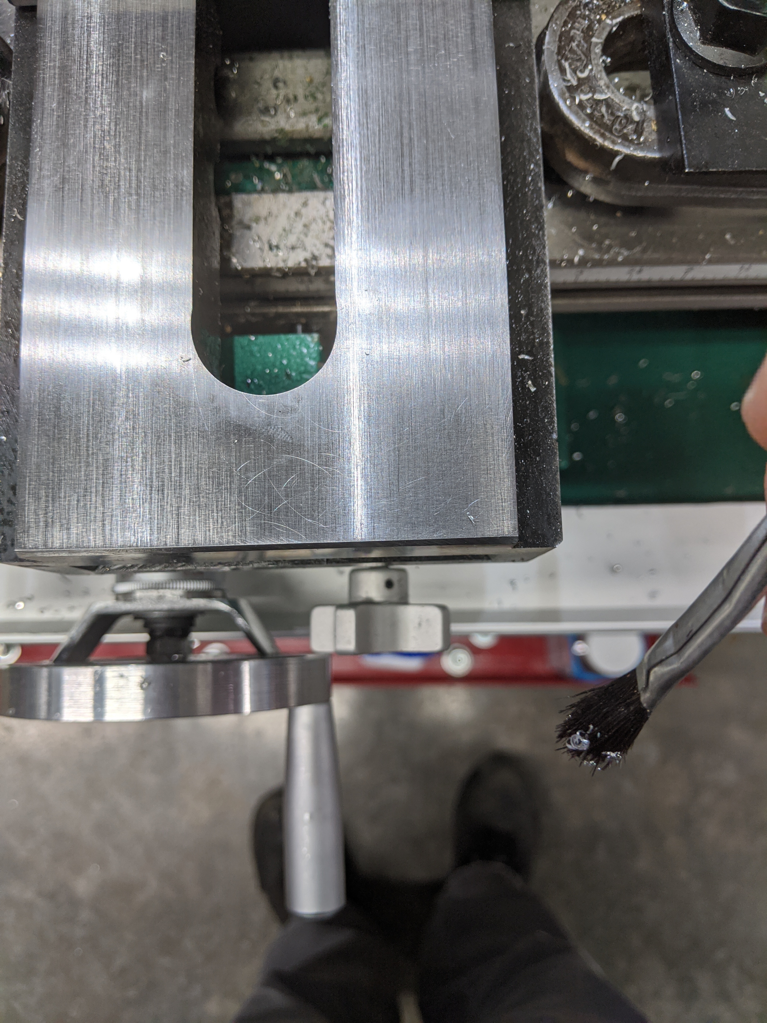
Note that access to the part on the table means being able to get an instrument on it (a caliper, a micrometer, a depth gauge, etc.) and being able to see that instrument's readings. Sometimes the best view of the micrometer is actually from behind the mill.
(3) Requirements for Tool Changes Within a Setup:
During each tool change, I need to access:
Requirements for Milling within a Single Setup
During the cutting operations (that is, after the initial part setup, during the several cuts taken on the part before it is removed for the next setup) I will also need to access:
Opening and closing big doors for these kinds of access would be cumbersome
I'll also need to be able to see:
So much of this enclosure should be transparent.
Drilling can be considered a separate operation with lesser requirements for catching chips (but greater requirements for access to the part and drill for lubrication and chip clearout. It also requires access to the quill controls, which are located well away from the table controls. For drilling, I'll need access to
It is possible that I can do this just by opening the enclosure doors while drilling.
General Remarks about Requirements & Approaches
I find that I need to measure my parts in the machine fairly frequently between cuts. (Maybe I'm just not a good enough machinist yet.) For this I'll need to get "up close and personal" again, so as to be able to get a micrometer, depth gauge, square, or other instrument onto the part (and to read it - and sometimes the setup is such that the most convenient way to read a micrometer on a part is from behind the machine). This requires direct and convenient access to the part. Opening doors is acceptable here.
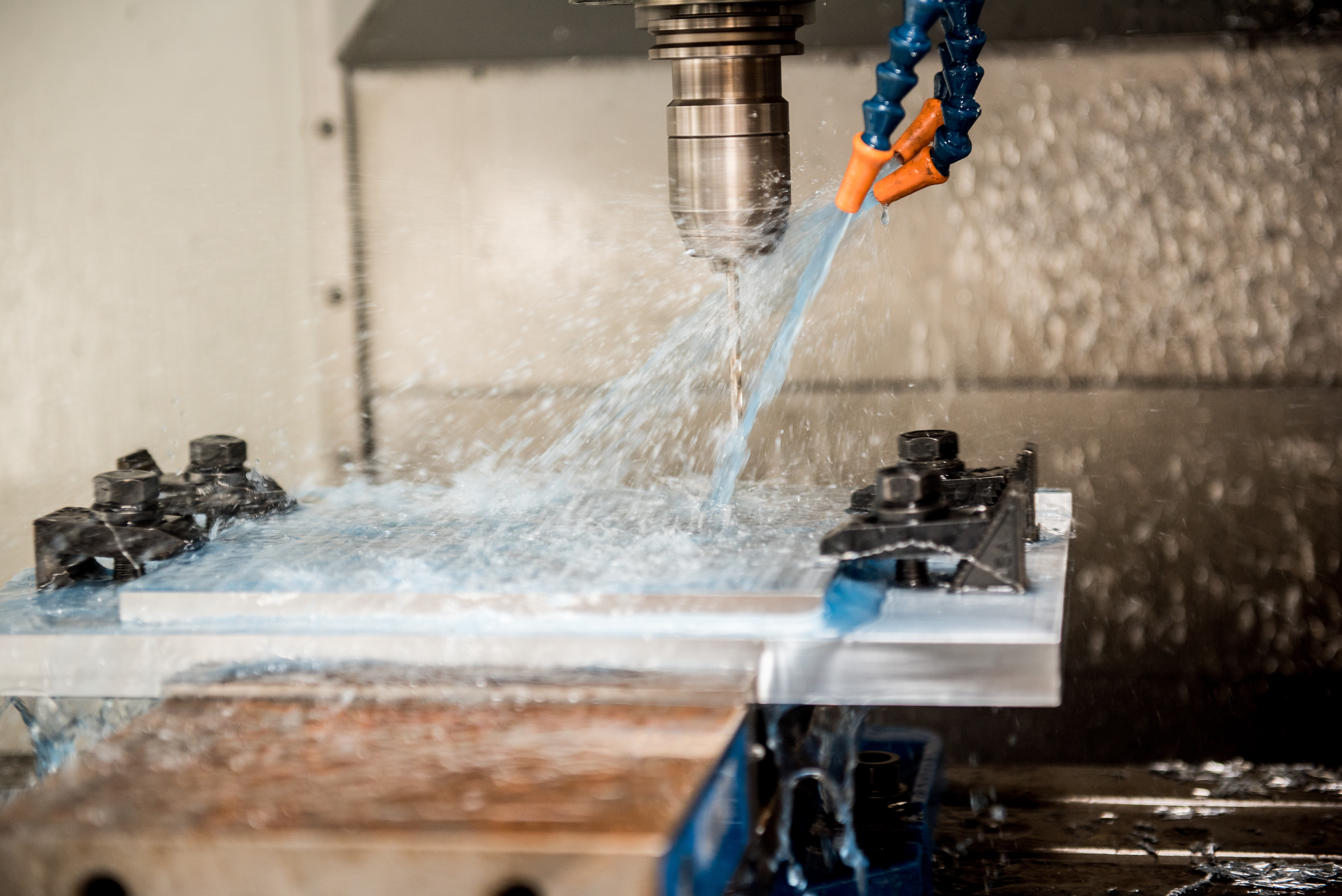
One partial simplification, for the present, is that I do not yet have flood cooling. So I don't need to make this enclosure waterproof. But I do plan to add flood cooling in the future, so I should design it so that it will be able to cope with flood cooling with only minor changes.
Here's an example of flood coolant use (shown on a CNC mill at a US Air Force base, making helicopter parts). This is a fairly restrained use. Sometimes the working area of a CNC mill when the flood coolant is turned on looks more like the inside of a washing machine.
There are several "levels of intensity" by which this problem may be approached. The most "intense" or thorough method is the complete, interlocked enclosure of a regular CNC milling center, as shown earlier.
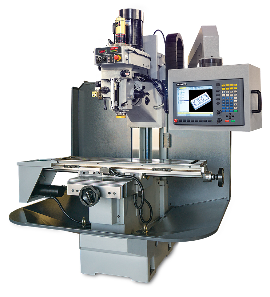
Going to the other extreme, you might just put a chip pan underneath and a backstop behind. Essentially, you're treating the mill like a manual lathe. I chose not to do this because mills throw chips in ways very different from a lathe. I just couldn't see this method working.
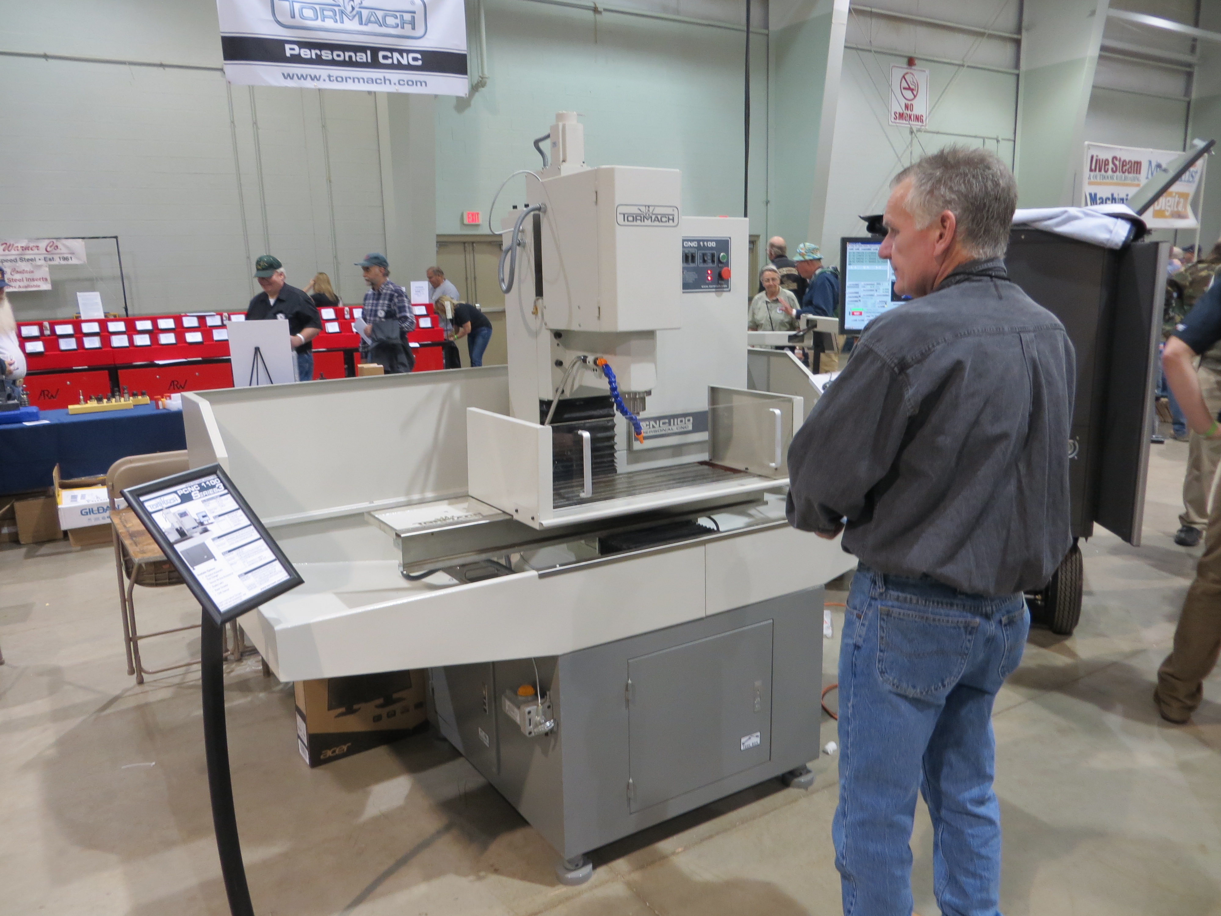
An intermediate position, endorsed by some, would be to construct a "chip guard" which more-or-less tightly surrounds just the table. (I'm not entirely sure that is what it is called, but it is a name I've seen used for it in discussions online.) The idea here is to keep chips at their source. This sounds appealing, but I chose not to go this route because I guessed that chips would escape out the open top. (Having now built my enclosure and observed chips bouncing off the tops of the sides, two feet above the table, I believe that my decision was correct. A chip guard without an enclosed top cannot really keep the chips in.)
(Above left: A Kent CNC mill with just a chip pan and backsplash. Above right: A Tormach PCNC 1100 mill with what I'm calling a "chip guard" around the table (and also a chip tray below and a backsplash). On display at the 2013 "Cabin Fever" model engineering show in York, PA. All of these features will quite effectively alter the distribution of chips on the floor.)
Should I keep DRO where it is, near the column (meaning that it will end up inside the enclosure) or should I move it outside (after the style of most CNC mills)? I decided to keep it inside, mostly because the existing cables weren't long enough to move it. This seems to be working well enough.
In my enclosure, I used hinges and I glued them in place, because space was tight and back-to-back flush fasteners would have been tricky.
What I learned from this experience is that I don't like using glue. Version 2, if/when I build it, will use only mechanical fasteners.
(A note about glue: I used "E-6000" brand glue because I had some on hand and I didn't want to open a new pack of 2-part epoxy. Afterwards, I noticed that gasoline is one of the solvents that attacks cured E-6000. While gasoline has no place in the workshop due to safety concerns, I do use other petroleum solvents in the mill (e.g., kerosene). So E-6000 was a mistake, but it might not be a problem. Less informed online sources often associate E-6000 with epoxy, but it is not an epoxy. According to its 2017 MSDS, it is "styrene, 1,3-butadiene polymer" with tetrachloroethylene as a solvent. In other words, it's synthetic rubber in dry-cleaning fluid.)
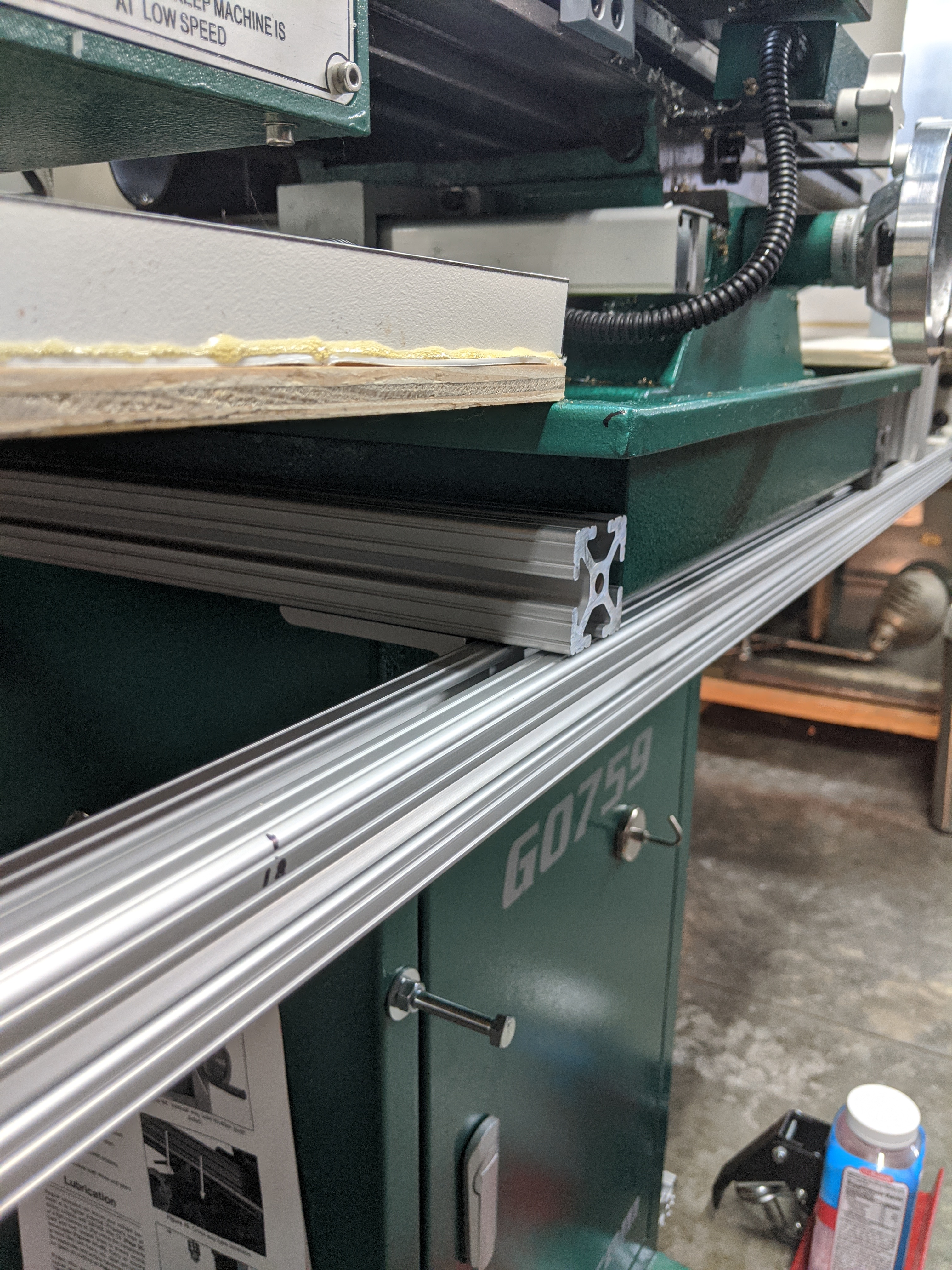
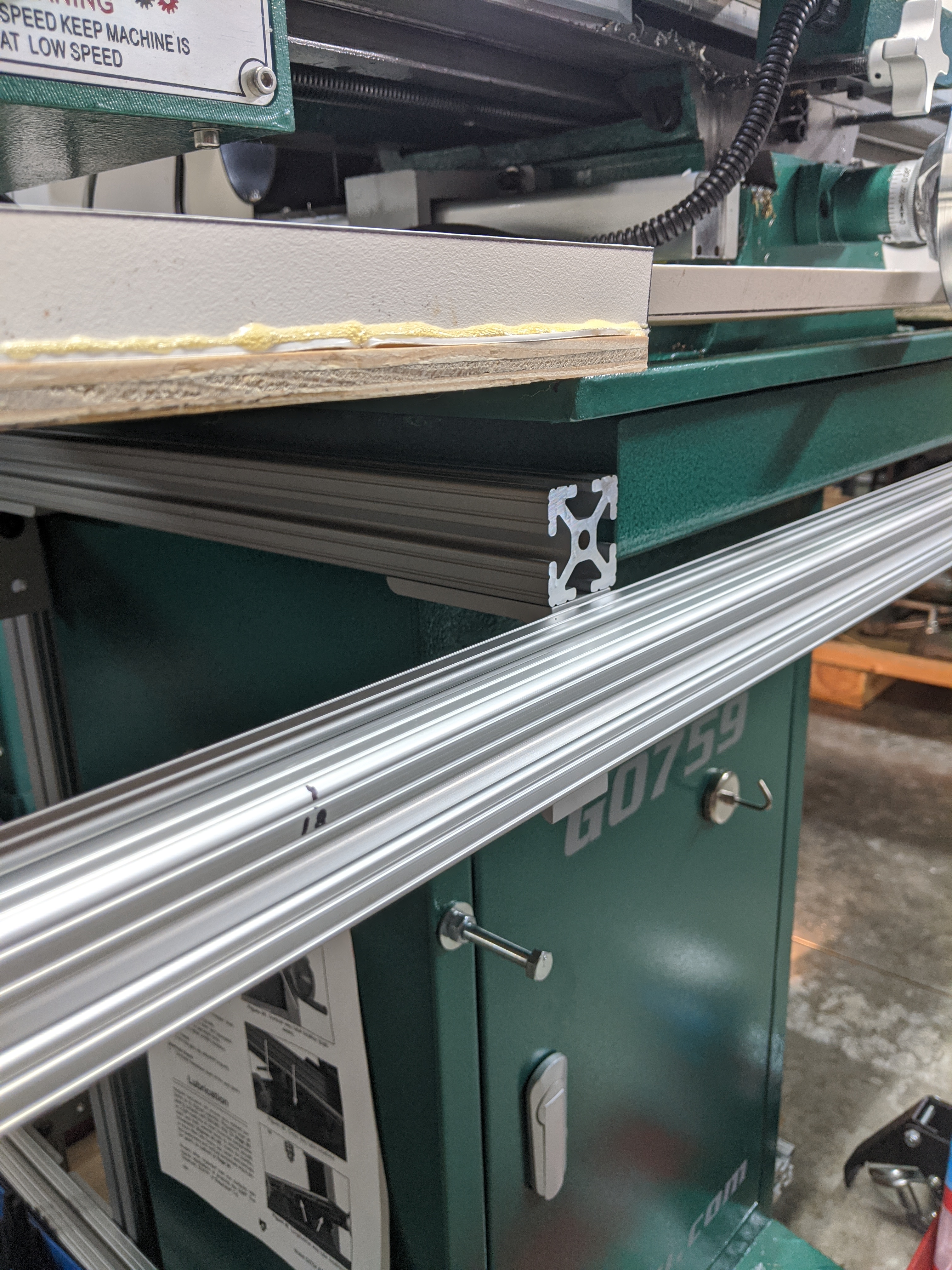
A few years ago, I planned a project in which I intended to use the "80/20" (brand) T-slot extrusion system in their 15 series (1.50 inches wide). See 8020.net. It's a good system; not the cheapest, but very well thought through and very high quality. Then I realized that I'd overdesigned that project (as usual) and the 15 series would be too heavy (their 10 series, 1.00 inches wide, would have been perfect). Since I'm a great believer in not returning things (because you never know when you might need them), I still had the materials. Turns out that a global lockdown during a pandemic is an excellent justification for this philosophy.
A couple of months ago, I'd started to use some of this 80/20 to build out from the G0759 pedestal to create a support for power distribution to the mill. I'd been meaning to extend this anyway to provide some shelving at the back of the mill (to hold lathe chucks, actually - my Clausing-Colchester 13" / Colchester Master 2500 is in the aisle behind the mill).
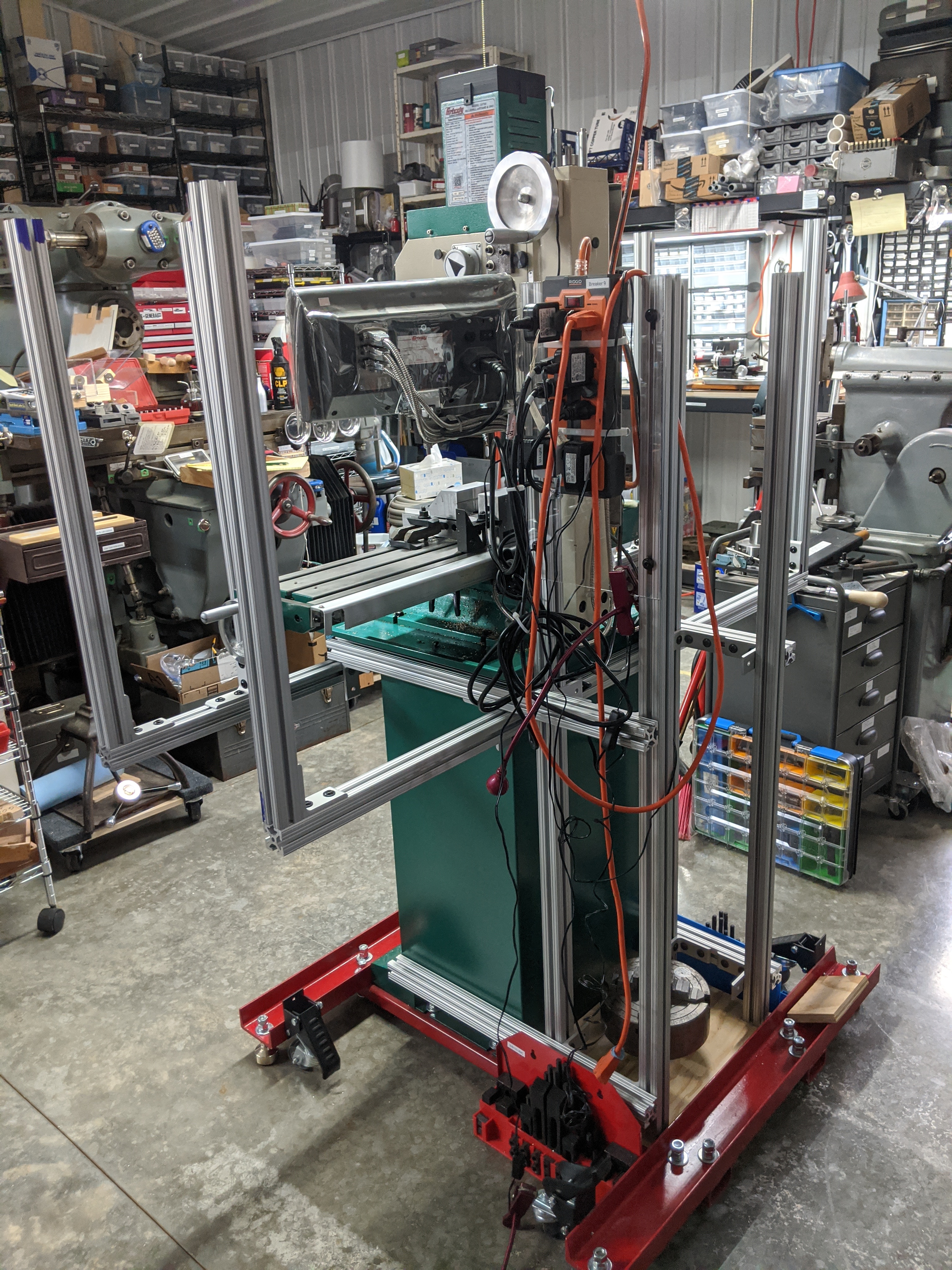
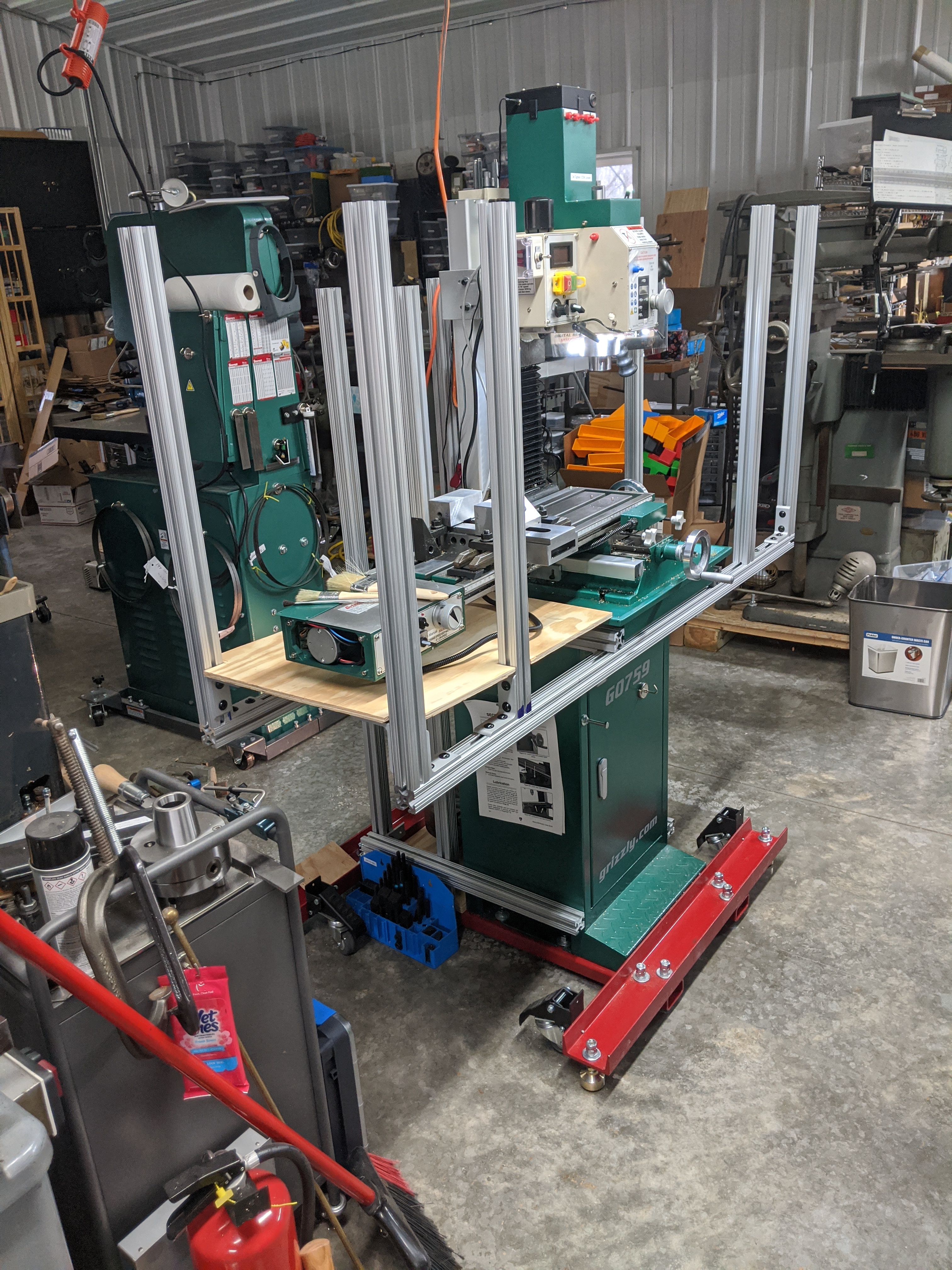
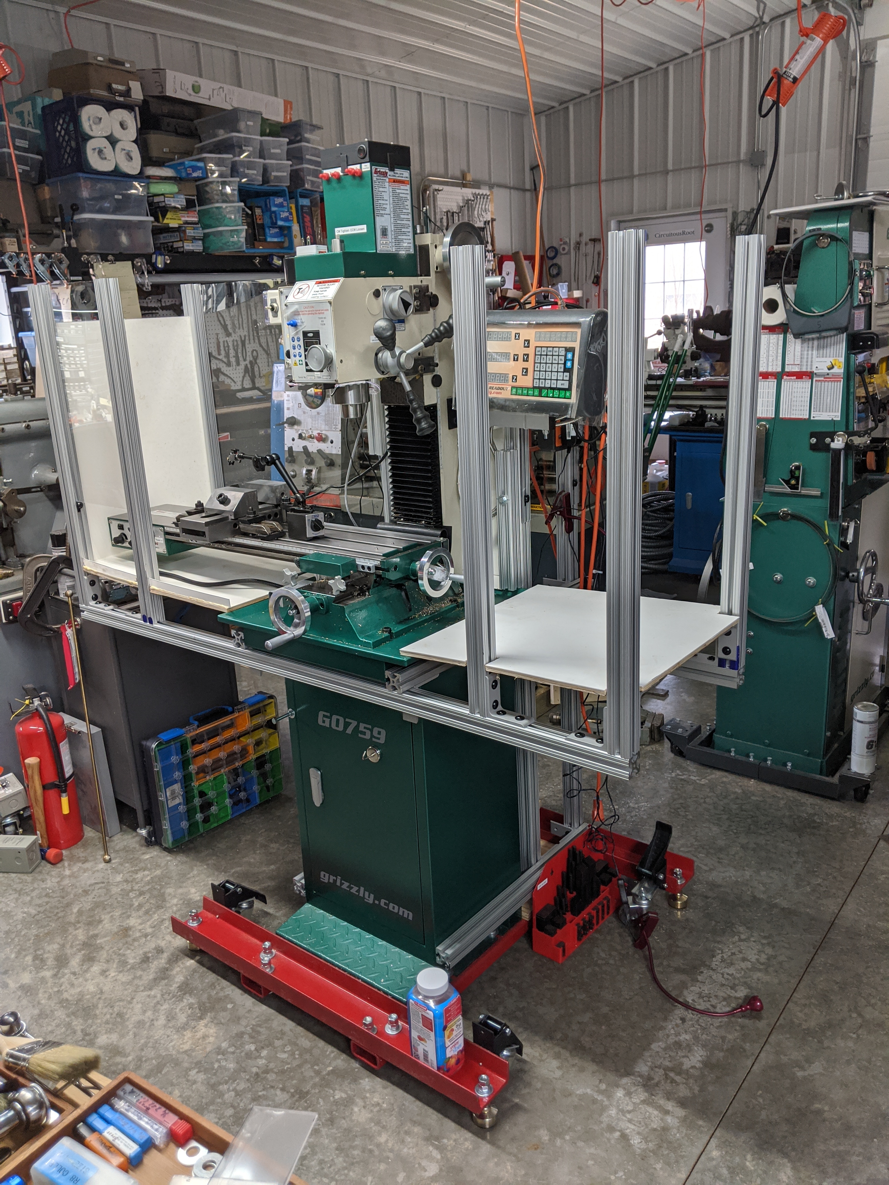
In this context, it was a pretty simple decision to start building out a framework for the enclosure using 80/20. The resulting structure is no great marvel of engineering, but it's surprisingly strong and it didn't take long to rig up. To fasten the 80/20 to the cabinet, I just drilled through the cabinet and used their screws and T-nuts from the inside.
In this first version, I built the chip tray below the table at a height so that it sloped into the existing chip tray on top of the pedestal. As noted elsewhere, this did work but it was a mistake. It works fine for gathering the chips, but it makes lubrication difficult. This mill does not have forced lubrication to the ways or the leadscrews, so to lubricate those of the table you need to get under them with an oilcan. As built here, you can't. To lubricate the table, you pretty much have to put oil on your fingers and use them to spread it on the ways and leadscrew. This works, but is obviously not optimal. The solutions would be (a) a forced lubrication system or (b) more space between the chip tray and the underside of the table or (c) both.
The other problem with the chip tray as built is that it doesn't stick out far enough toward the user. It was intended to be flush with the front of the existing pedestal (this was a mistake; see the "Doors and Front" section below) and I was trying to preserve Y-axis handwheel access. But chips fall out the front. It needs to be lower (see above) and to stick out more in the front.
Since this enclosure is a prototype and since I'm not using flood coolant, there was no particular need to build this chip tray very well - and I didn't. I did some measuring and transferred these measurements to sheets of scrap cardboard. Then I cut the cardboard to make a piece I could test-fit. When that worked, I used the it as a template to cut out two sheets of scrap 3/8" plywood (because I had it).
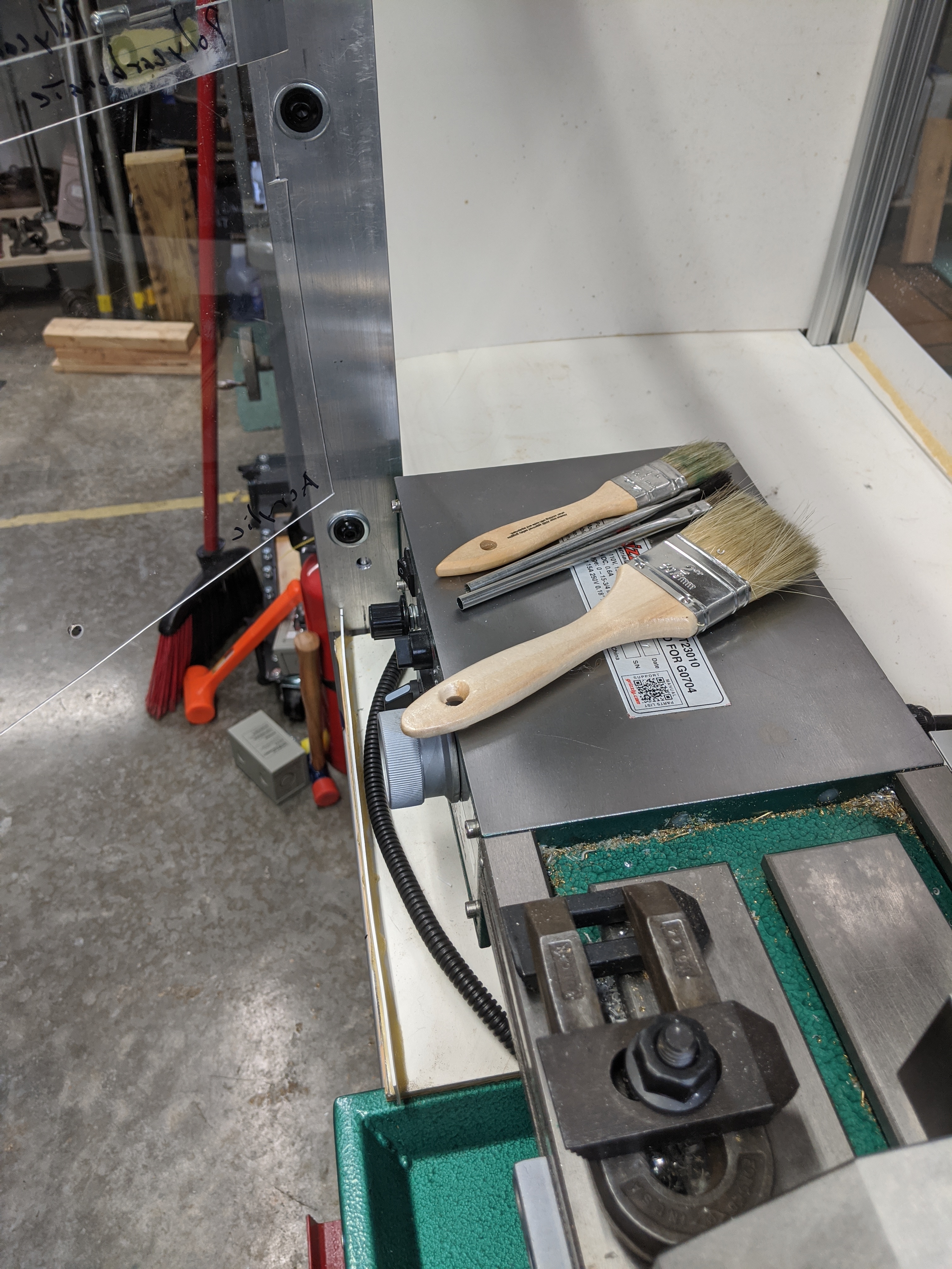
Because I'm not using flood coolant, the plywood alone would in theory have been enough. But I am squirting a fair bit of cutting oil on the parts and this would just make a soggy mess on rough plywood. So I covered it with pieces of "POLYWALL Utility Panel" / "PLAS-TEX Waterproof Wall Panel" (see the posting on my First Electro Workbench for more about this surprisingly useful material).
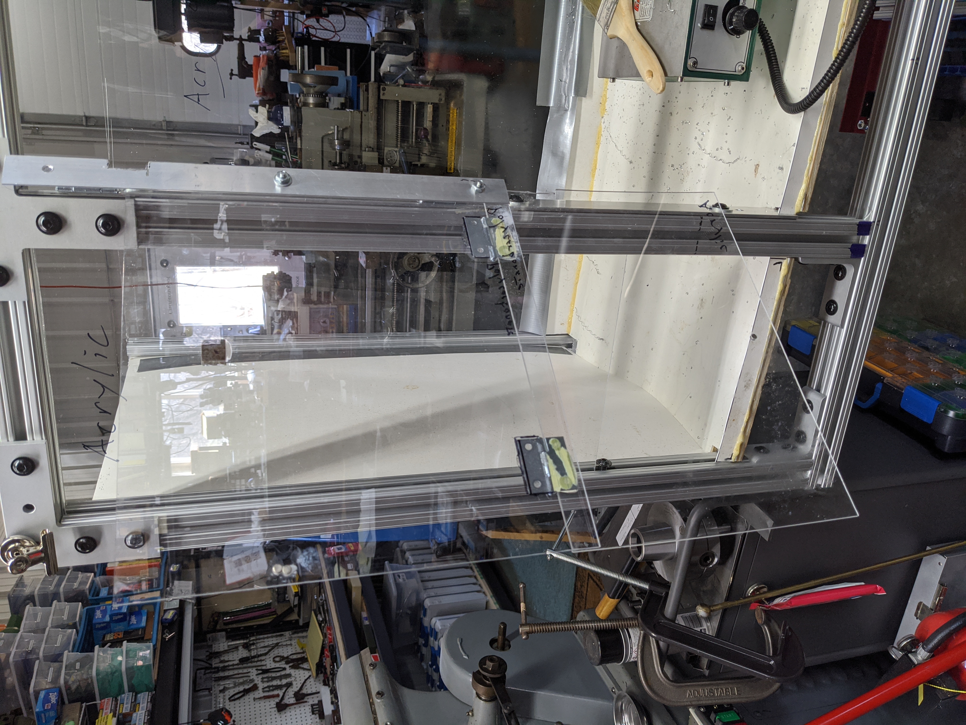
Because this enclosure doesn't have to be watertight (in this version), the sides were easy: I just slipped panels in the slots of the 80/20 extrusions.
Ideally, all of the panels would have been polycarbonate. Polycarbonate (of which "Lexan" is one brand) is much nicer to work with than acrylic (of which "plexiglas" is one brand.) Polycarbonate is also impact-resistant whereas acrylic shatters. That's why your reading glasses are not acceptable as safety glasses - they're made of acrylic. Nick Carter conducted a sobering test of this using an air gun pellet as a substitute for a bit of shattered tooling coming off of your lathe or mill. Read and understand it and you'll never use your reading glasses as safety glasses again: http://anotherairgunblog.blogspot.com/2014/06/dollar-store-reading-glasses-are-not.html
(The enclosure is most emphatically not a substitute for wearing appropriate eye protection in the workshop. But every extra layer between you and the shrapnel of an exploding cutter is one more bit of protection.)
Unfortunately, I didn't have enough polycarbonate sheet on hand. So some of the panels are acrylic. Unfortunately, I didn't have enough acrylic either. So some of them are cut from scraps of POLYWALL/PLAS-TEX. Notes to self: (1) Get enough polycarbonate for the next version. (2) Stop buying acrylic, even though it's cheaper.
To keep oil/etc. from leaking over the edges of the chip pan, I built up a small edge around it by gluing strips of POLYWALL to it. I tried several different glues. The one that worked was "Gorilla" brand urethane glues (a no-name urethane glue failed, as did a name-brand plastic-specific glue - but there is no reason to assume that "PLAS-TEX" is a plastic within the intent of the glue). I could/should have sealed this up a bit better around the vertical posts.
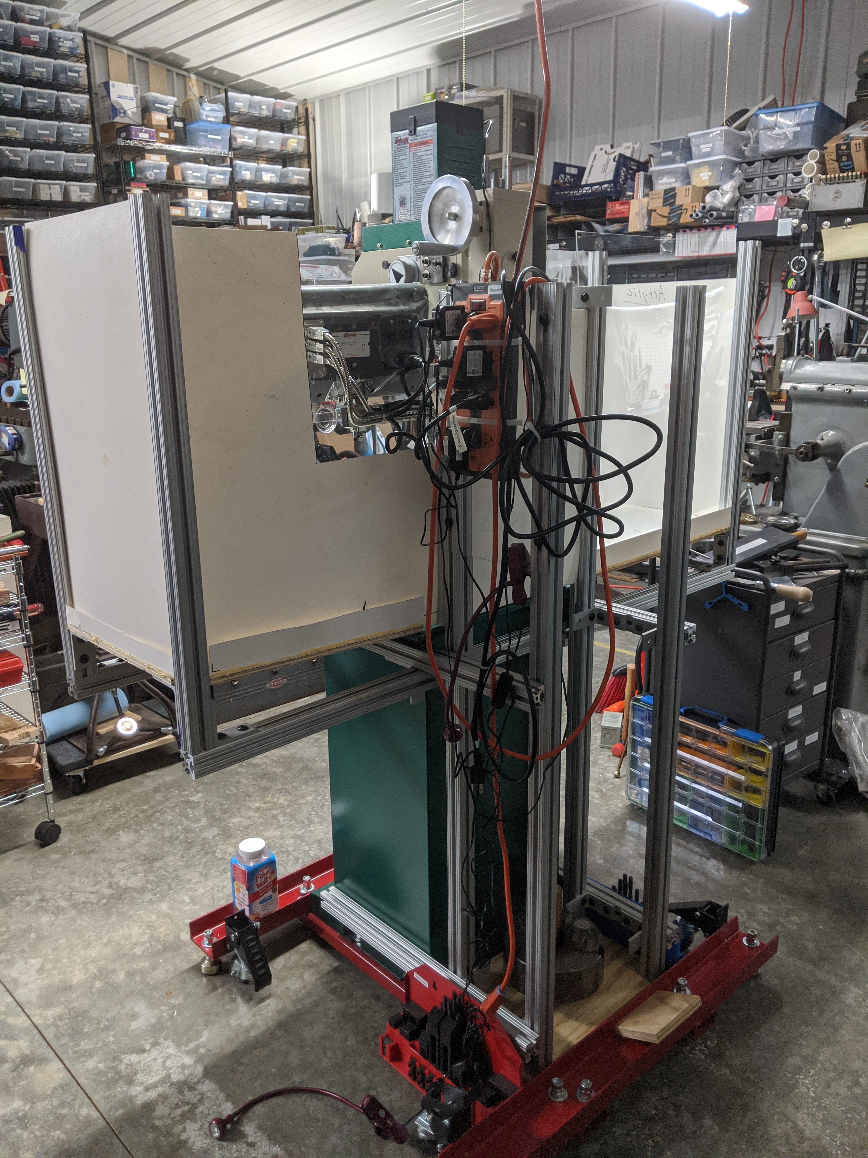
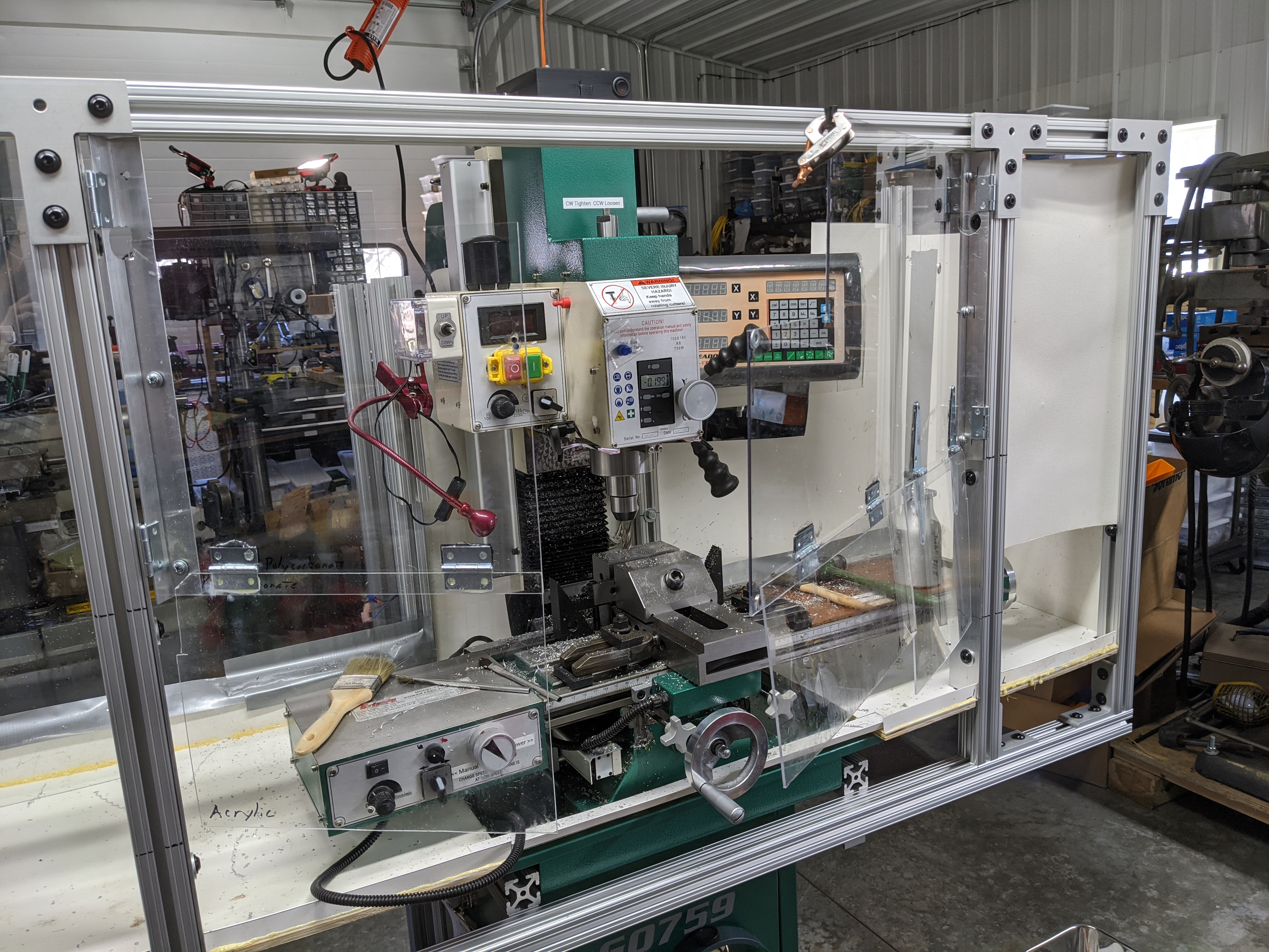
The sides and back are ugly, but they work pretty well. I've just done a cut-out where the mounting for the DRO interferes. I think some chips are escaping out that way; I might drape a cloth over it to catch them.
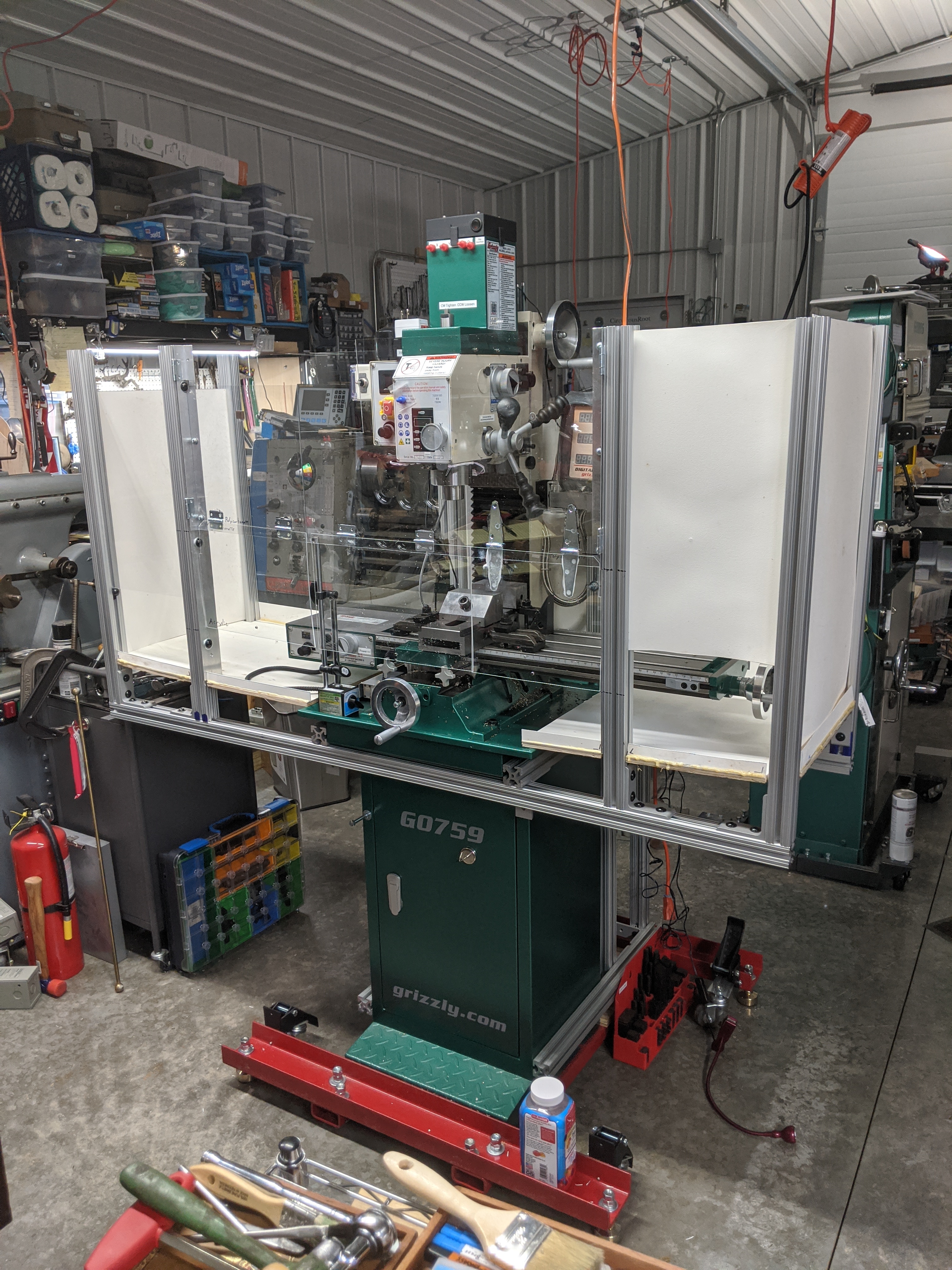
The front is the tricky part, because it must fulfill two incompatible requirements at the same time: keeping stuff inside from getting out and allowing me (outside) to get in. For a non-flood-cooling situation, the solution here works pretty well. (Flood cooling would require improvements.)
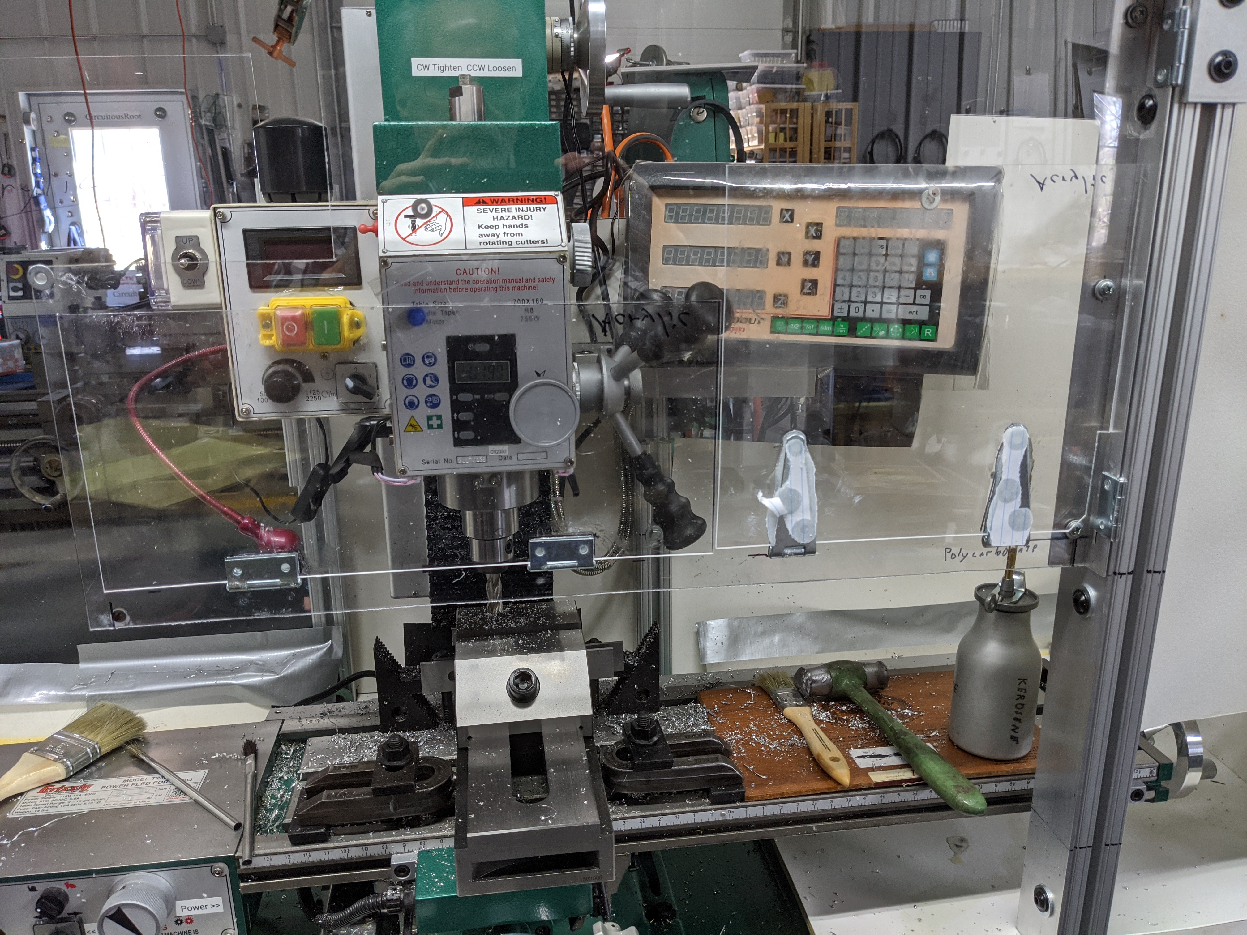
I'd divided up the front into a triptych, just on the intuition that I'd need most access to the central portion (but that I wanted more support than the far sides alone would give). So in the outer two portions I dropped in two panels but left the lower few inches open. The idea was that this would allow me to reach in to control the table power feed (left) and X-axis handwheel (right). This works surprisingly well. (In the photo below left, it is easy to see this gap on the right because that panel is POLYWALL. There is a gap below the acrylic panel on the left, too.)
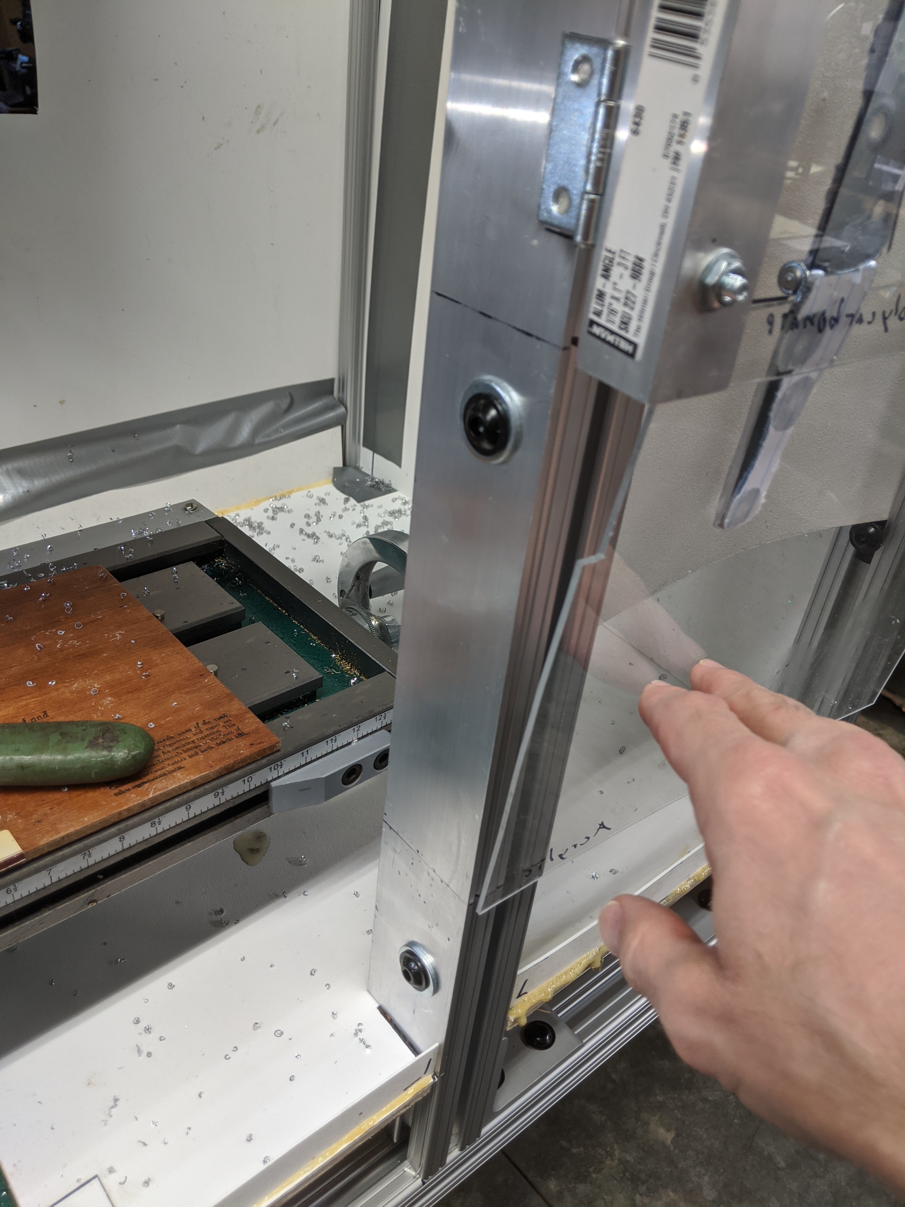
I did, however, discover a problem the first time I actually moved the table. This comes from designing on-the-fly and not really measuring everything first. As you can see below (right) I failed to take into account the thickness of the vertical posts.
Of course, mistakes such as this highlight the advantage of working with a constructional system. It was easy to move the entire front forward by 1.5 inches. (Of course, this left a 1.5 inch gap in the side panels and chip pan. Most of these gaps were filled with appropriate patches - except the last one, where I cheated and just used duct tape.
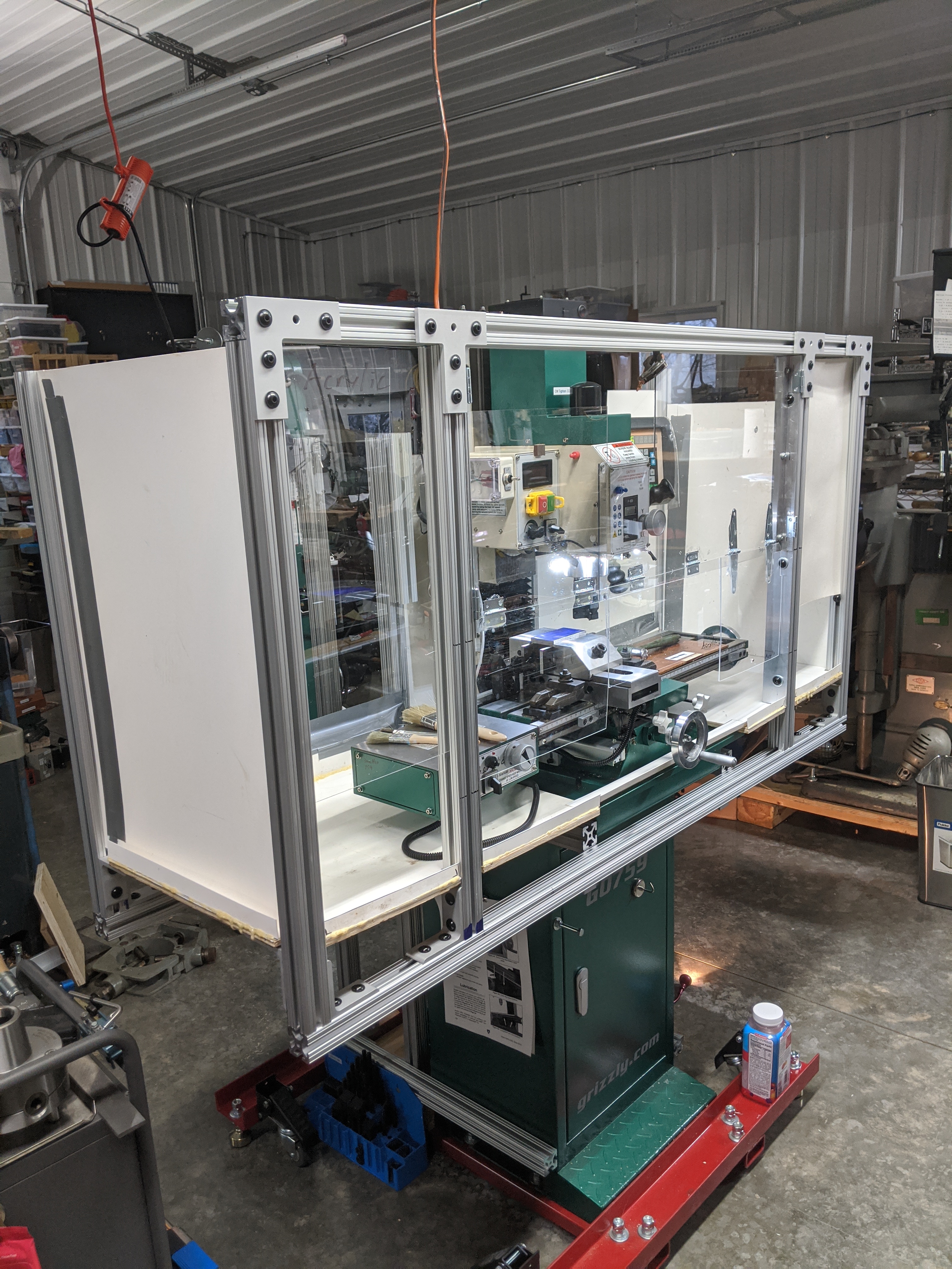
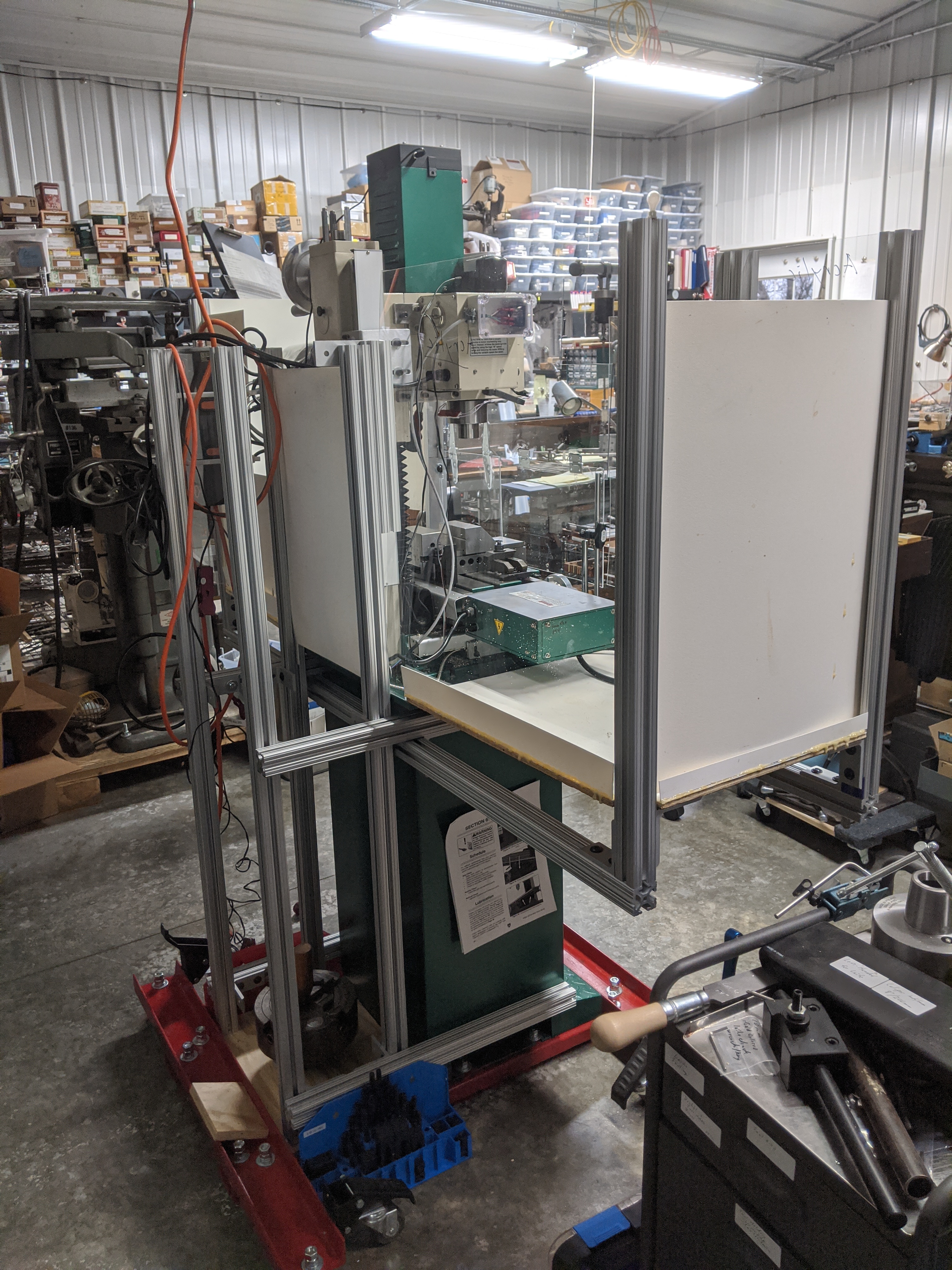
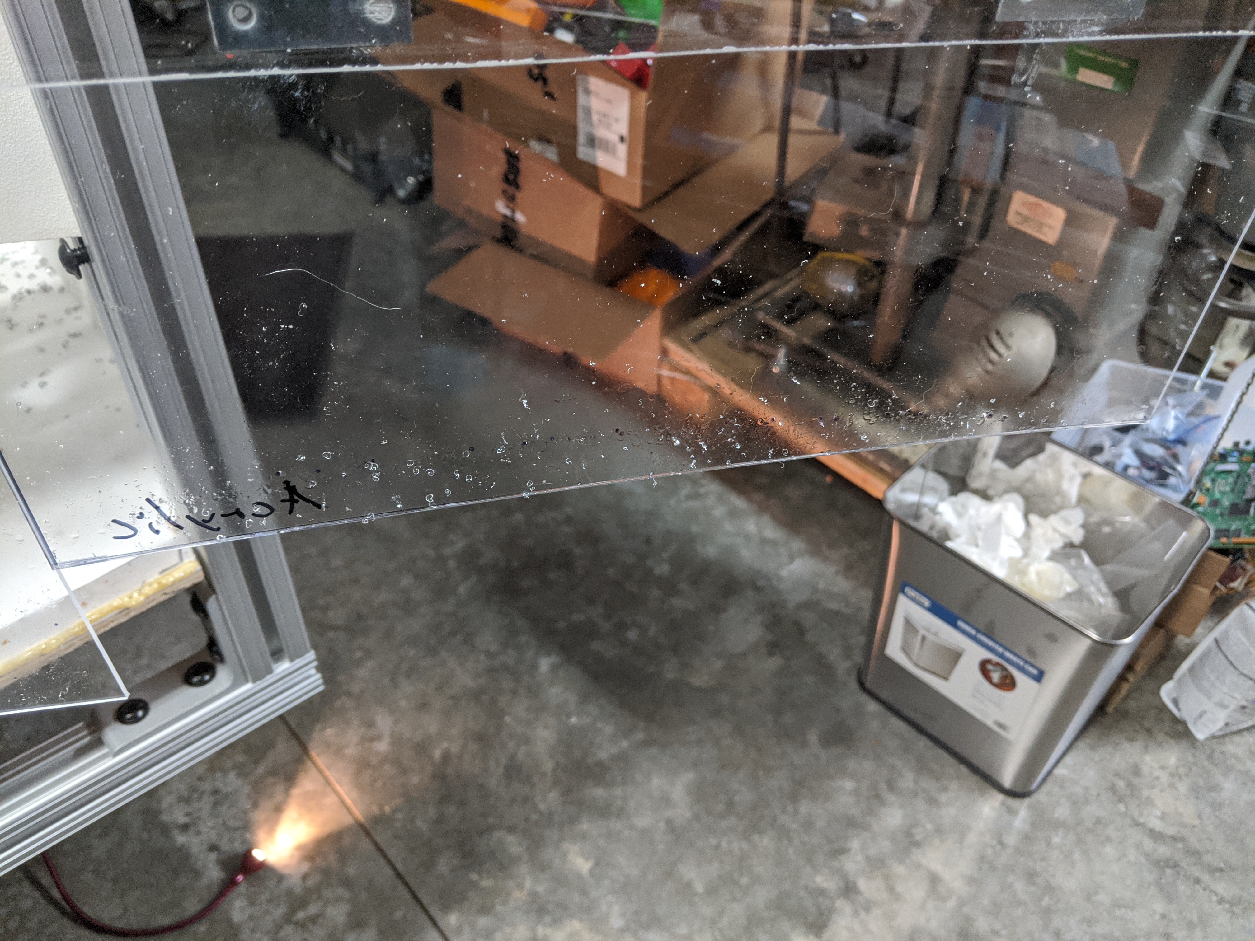
In trying to illustrate the arrangement of the doors in the front, I (re)discovered the fct that it is difficult to take pictures of transparent things. Here's a general view. Imagine that the left third swings out and to the left and that the right two thirds swings out and to the right.
The right-hand door doesn't go up to the full height, so I can reach over it to use the power buttons and speed control. The lower portions of both doors swing up (and can latch in the up position). This allows me to reach in to do things like squirt coolant on the workpiece during cutting operations.
The left and right hinges are properly screwed in. The hinges for the vertical panels are just glued on. (This seemed like a good idea at the time. In the next version I'll use screws.) The right door is held shut by a piece of scrap rubber at the top (which fits into one of the slots of the 80/20). It's held in place by a Kant-Twist clamp - which is a clever thing to do until I need just one more clamp for something else. The left door is held shut against the right door by a magnet. (Superglue a magnet to the door. Superglue a washer to the other door for the magnet to act upon. Then superglue a regular steel washer over the nonmagnetic stainless steel washer I'd used originally. Sigh.) The outer two vertical panels are held up by magnets. The inner one has slightly misaligned hinges and holds itself up by friction.
First Cut and Initial Evaluation
It works. It has many flaws, but it's a whole lot better than flinging chips over half the shop. (Indeed, its biggest problem is that it may be a temporary solution which becomes permanent.)
The system of doors and access openings along the bottom front works pretty well. (Access to the power/speed controls is a little awkward, but ok. I need similar access to the Z-axis handwheel.)
Here are some of the problems I've noted so far:
‣ The sides are none too high. I didn't spot any chips which had escaped out the top, but I saw many chips bouncing against the upper portions of the back left side. This leads to two conclusions: First, for the next version I should consider either higher sides or a top or both. Second, the idea of using just a "chip guard" around the table won't meet my goals. Such a solution might work if you're doing flood cooling and the coolant stream is dragging the chips down (I don't really know; I haven't tried this). But there is no way that such a low-walled chip guard will contain face mill or flycutter chips cut dry or with hand-sprayed coolant.
‣ I do bang my head on the horizontal bar across the front. Moving it up six inches would fix this.
‣ Chips do bounce out of the low openings in the front. Extending the chip tray out in the front may help this, but it may be that this problem is inherent in any enclosure which must have an opening. The only complete solution would be complete enclosure, but to do that you'd have to make the controls remotely operated. By the time you've done that, you've pretty much built a CNC mill, and have in any case lost the feel of a manual mill.
‣ There is a problem with the right swinging panel. As it is, if this panel is in its regular (down) position when you open the right door, it blocks access to the table handwheel. This is inconvenient during setups. So right now you have to remember to swing it up before opening the doors for setups. One solution would be to allow it to swing both in and out (so that you could swing it up with the door already open).
‣ It is inconvenient to have to open up the doors in order to access the Z-axis handwheel (its location at the top of the column isn't great in the first place, but that's where it is). You want to be able to take successive cuts, downfeeding between each, without turning off the spindle or opening the doors. (Making this control remote, by putting a stepper motor on Z, is not a good solution by itself. It would mean I'd lose the "feel" of the Z-axis leadscrew and would have great difficulty addressing backlash (this is very important in setting tool heights). If I did this, I would also have to replace the Z-axis leadscrew with a ballscrew to eliminate backlash. Perhaps I should do this anyway, but it moves the whole project in the direction of CNC-conversion rather than manual mill enclosure.)
‣ As-is, the doors get covered in cutting fluid and chips. This isn't a big problem now, but it might become a bigger problem when I go to flood coolant (because the doors will then be dripping when they're swung open). Perhaps this is why real CNC machines have sliding doors?
So, as intended, I've learned a lot. For the next version:
In addition, in building a Version 2 it would make sense to make the whole thing watertight below the table level and water-resistant above, so as to allow the addition of flood cooling without major modification.
Also, the more I think about it, the more I like the fold-down-panel feature of that 1980s vintage Deckel FP2. 80/20 makes hinges for their system, so it should be relatively easy to do.
I'm beginning to think that the underlying reason for several of the design flaws in this first version is that I retained the Grizzly stand. It's a fine stand for the mill as supplied, but it was never intended to be festooned with stuff the way I have done. In particular, if one wants to use its existing chip pan, then space underneath the table will be limited. But if one tries to go below this level then the new bottom of the enclosure will interfere with the cabinet (and if you use flood coolant, things are going to leak). It might be best to discard this cabinet/stand entirely. Just weld up a frame which goes all the way to the floor in the footprint of the enclosure. Support the mill on a pedestal as a part of this and put a new big chip pan at any convenient level. With some clever designing, this could be made to accomodate equipment for flood coolant. (In other words, this project may have been an exercise in coming to understand why CNC mills look like big boxes.) This would be a pretty major project, though.
Thought about alternative: In a hobby shop, space is always a problem. (In a commercial shop, if space is a problem then it is a part of your responsibility as shop owner to acquire premises adequate for the conduct of your business.) This means that big enclosures are also a problem, because they eat up space very quickly. They also do so in a particular way. Say you only use your mill every other day, and space is tight. You could, plausibly, install it so that the table sticks out into the aisle when in use but is moved out of the way when idle. That's not a perfect solution (more space is the perfect solution) but it works. But a big boxy enclosure is conventionally designed so that it accomodates the entire X-Y footprint of the table as it moves. It will always stick out into the aisle. What if, instead, yu built an enclosure that accomodated the table in its X dimension (Y is less critical) and moved with the table. I don't mean a "chip guard" as described above. I'm thinking of a full-size enclosure, probably floor-mounted and on wheels. In rough terms, this could be about 1/3 narrower than a conventional full enclosure.
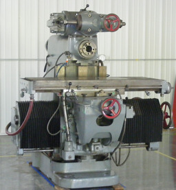
Finally (but not directly related to Version 2) it is becoming more and more apparent that a pressurized direct lubrication system for the ways and leadscrews really should be the next major modification. The trouble with this is that I have, through experience, come to a cardinal rule: there must always be at least one operational mill (ditto lathe) in the shop at all times. So before I go tearing up this one to install lubrication (or tearing up everything to fabricate a new base) I need to get my SHW UF-2 mill operational.
(The photo above shows the SHW UF-2 mill just after I moved it into the shop, before the walls behind were covered in stuff. Click on the photo to go to my Notebook on this mill.)
All portions of this document not noted otherwise are Copyright © 2020, 2022 by David M. MacMillan.
Circuitous Root is a Registered Trademark of David M. MacMillan.
This work is licensed under the Creative Commons "Attribution - ShareAlike" license, version 4.0 International. See http://creativecommons.org/licenses/by-sa/4.0/ for its terms.
The photograph of a Haas milling machine at the NREC is copyright 2009 by Wikimedia Commons user "Rob NREC" and is licensed under the Creative Commons Attribution-Share Alike 3.0 Unported license. Source: https://commons.wikimedia.org/wiki/File:NREC_Machine_Shop_Workstation.jpg
The photograph of a Mori Seiki FM-1 vertical machining center is by Wikimedia Commons user "EvasiveMobile" (2018) and has been released by them into the public domain through the Creative Commons CC0 1.0 Universal Public Domain Dedication. Source: https://commons.wikimedia.org/wiki/File:Mori_Seiki_FM-1.jpg
The photograph of a Kent CNC mill is by Wikimedia Commons user Mike Zielinski (2017). License: Creative Commons Attribution-Share Alike 4.0 International. Source: https://commons.wikimedia.org/wiki/File:Kent_USA_CNC_Bed_Mill_TW-32Qi.jpg
The photograph of a Tormach PCNC 1100 Mill is by Wikimedia Commons user 1sfoerster. License: Creative Commons Attribution-Share Alike 3.0 Unported. Source: https://commons.wikimedia.org/wiki/File:Mill2.JPG
The photograph of a flood cooling is by United States Air Force Staff Sargeant Damien Taylor, taken at Dover Air Force Base, Delaware, Jan. 6, 2019. As an official photograph by the United States federal government, it is in the public domain.
Presented originally by Circuitous Root®


