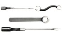
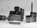
The Plates in the various editions of the Thompson manual do not show everything. The Parts Lists identify almost (but not quite) everything, but do not illustrate anything. This is an attempt to join the two, with photographs of actual parts and comments as necessary.
The material here covers only the American (Lanston) Thompsons, not the English machines.
For an actual (but un-illustrated) Lanston parts list, see the 1942 Lanston Monotype Thompson Parts Price List You may also wish to refer to the 1925 TTMCo manual, which has better pictures but old-style part numbers and the 1956 manual, which has poorer pictures but new-style part numbers. But, actually, the edited version of just the 1956 plates and their identifications should be far easier to use.
To understand the part symboling ("part numbering") system, see the Bancroft / Monotype Part Symboling System discussion in the Part Symboling Systems Notebook. The part symbols as quoted here will generally be from the 1942 Lanston Monotype Machine Co. Parts Price List for the Thompson. As presented there and quoted here, these part symbols often include lowercase alphabetic prefixes (e.g., the 'b' in b42TC38). These indicate revisions. Obviously, I do not know for certain if the parts I'm showing here are at the same revision level as indicated in the 1942 parts list. Unless I have some reason to believe that I'm showing an earlier version, however, I'll keep these alphabetic prefixes without further comment.
For a view of the parts in context, see ../ Disassembly and Reassembly -> A Complete Teardown.
No original manufacturing drawings survive (and only a very few field engineering drawings survive), but I'm in the process of trying to create detail drawings for each of the parts. This is a big project, of course, and it is far from complete. For progress (or lack thereof) so far, see: ../../ Reverse Engineering.
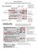
How to Read a Lanston Thompson Parts List
A two-page chart explaining the symboling system used for the Lanston Monotype Machine Company's Monotype-Thompson Type-Caster (as of at least the 1942 revision of the Parts Price List).
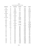
Lanston Standard Screw Threads
Data transcribed from the American Typecasting Fellowship Newsletter No. 3 (July 1979), p. 6. Original data from Hyden [Hayden?] Sizemore.
Please note that there may be errors in this (the notes to the file outline some of these). If you find any, please let me know so that I can correct them.
I used the "LibreOffice Calc" spreadsheet to generate this transcription. The icon at left links to a PDF generated from it. Here's the original .ods format spreadsheet file: lanston-monotype-standard-screw-threads.ods

Index of Classifying Numbers
An index or list of the Lanston Monotype "Classifying Numbers" for parts which are used on the Thompson, arranged by number. These numbers group together identical common parts (such as screws, nuts, pins, etc.) which are used in various places throughout the machine (and thus have different part numbers for each use). For an explanation of the "Classifying Number" system's principles, see the Notebook on the Bancroft / Monotype Part Symboling System.
As the specifications for these parts are reverse engineered, I'll add them to this list.
Identifying Thompson Matrix Carriers and Holders
This is a ROUGH DRAFT, last updated in 2012. I'm quite sure that there's still incorrect information in it - this isn't an easy topic, actually. So if you need it for understanding your own machine, use it as a source for further questions rather than as answers. If you're just researching the Thompson in general, don't (yet) believe a word in it.
Group 54TC - Mold Stand
[NOT DONE]
Note that the four screws in the Mold Cap which press down on the Mold Top Block and Mold Jet Block are a part of the 54TC Mold Stand, as are the Adjusting Eccentrics which pull up on the Top and Jet Blocks. But the Jet Block and Top Block Lifting Studs (b42TC38/b42TC49) and Yokes (a42TC40/a42TC51), which appear right next to them above the Mold Cap, are part of the 42TC Mold.
Group 58TC - Motor Base
At present this just covers group symbol Xa58TC for Lanston Monotype-Thompson machines from s/n 10,300 on (not the motor mounts for earlier machines or for English machines).
Group 59TC - Motor Pinion
[NOT DONE] The Motor Pinion for Lanston (i.e. American) Thompsons, at least in later practice, is a 30-tooth involute-system spur gear. 12 Diametral Pitch. 2.5 inch Pitch Diameter (which gives a 2.625 inch outside Diameter). 14 1/2 degree Pressure Angle system. 0.625 inch bore, with a keyway. 1 1/4 inch thickness. It is made of "fiber." The closest commercially available gear at present is Boston Gear p/n QDH30 (12 D.P., 14.5 P.A., 2.5" Pitch Diam., 30 Tooth, 0.625" Bore). This Boston Gear part is made of Grade C cotton-reinforced phenolic. This gear is only 0.750 thick, though. (Specifications reverse engineered by Sky Shipley and DMM.)
All portions of this document not noted otherwise are Copyright © 2012 by David M. MacMillan and Rollande Krandall.
Circuitous Root is a Registered Trademark of David M. MacMillan and Rollande Krandall.
This work is licensed under the Creative Commons "Attribution - ShareAlike" license. See http://creativecommons.org/licenses/by-sa/3.0/ for its terms.
Presented originally by Circuitous Root®
Select Resolution: 0 [other resolutions temporarily disabled due to lack of disk space]