Diagram X
Diagram Y
The Rolling Ball Web
An Online Compendium of
Rolling Ball Sculptures, Clocks, Etc.
By David M. MacMillan et. al.
Note: The following was written and illustrated by Piet Reichwein to describe the design of one of his works. It appears here with his permission. I believe the work under consideration here is the one displayed in the hexagonal enclosure as shown in the photos on the main RB Web page devoted to Mr. Reichwein's work.
I would like to thank Mr. Reichwein for writing this. It is the best technical description of a rolling ball piece yet written. This text, and its wonderful diagrams, are a great contribution to the field of rolling ball work.
The formatting of this document for the Rolling Ball Web was done by David M. MacMillan. I apologize if I have unintentionally introduced any errors. When I have added comments, I have enclosed them in [square brackets].
This sculpture was designed and constructed by Piet Reichwein, retired teacher. The sculpture is now on display in the school building where it was made, the Damiate College in Haarlem (Holland). Approximately 4000 hours of work (and a great deal of pleasure) went into it over four years. All rail tracks are made out of steel wire (3 and 4 mm), all permanent connections are soldered with brass. The sculpture makes use of 84 snooker billiard balls (size 44.4 mm) and is driven by a small electrical motor.
The main parts of the elevator are four vertical rods. These rods are being pushed up 160 mm every ten seconds by a crankshaft and go down by their own gravity. While going up they take balls with them, while going down they are empty. The balls run from one rod to another and by steps of 140 mm they go on to a higher level.
|
Diagram X |
Diagram Y |
The whole sculpture consist of two independent systems X and Y (see Diagrams X and Y). Two elevator rods for every system. Balls in the Y elevator make ten steps. In the X elevator eight steps. In the X system there is also a big wheel. A pullrod, connected to one of the elevator rods, turns the wheel 18 degrees. Balls enter the wheel in the lowest position and are pushed out in the top position, where they roll to the eightsteps X elevator. The total level difference between in and out for Y is 1400 mm and for X is 2020 mm. Once the balls have arrived at the highest level it is only gravity which makes them roll. Every action always finishes on a lower level.
 Picture 1 - T Model Rail Switch |
 Picture 2 - Fork Model Rail Switch |
The entire sculpture counts 15 rail switches. There are fork models and T-models. Some bring the balls from two different directions together on one track, while other do the opposite. Every passing ball will activate the switch, so when the first ball takes direction A, the next one will take direction B.
Diagram X [repeated]
DIAGRAM system X
A	=	Elevator
B en C	=	Pendulums
J	=	Tumblers
D	=	Collision
E	=	Step by step track/ladder
F	=	Loopings
G en H	=	Discs
l	=	Railpoints
Picture C - Pendulum
There are two pendulums. All balls coming from the elevator will first go to the pendulums. When the first ball goes to pendulum B the next will go to C, and so on. So every 20 seconds they get a push, which keeps them moving constantly.
Picture J - Tumbler
The balls going in the direction number 4 will go to the tumblers. There are seven tumblers. Each incoming ball will turn over a tumbler because of the difference in length. Each next tumbler is always on a lower level, so the balls go from one tumbler to another and, after tumbler number seven, back to the elevator.
Picture D - Collision
After passing the necessary switches, balls number 1 and 2 (in that order) in turns take position for collision. Number 3 will set them free at the same moment. After the collision the balls bump backwards and roll to the step-by-step ladder.
Picture E - Step-By-Step Track
This is a slightly sloping double rail track, in order for the balls to move by their weight. Both tracks have 11 "locks", which allow the balls to move only a short way each time. Each ball releases the "lock" of the ball in the other track. In this way the balls take turns rolling along the 1.8 m long ladder on their way to the next action.
Picture F - Looping
The balls 1 and 2 in turn take position and are again released by ball number 3. While rolling down with great speed they make a looping. Because of the "wrong" rotating direction and it's contact with the lowest rail, the ball slows down suddenly. It then rolls in the opposite direction towards the dis.
There are two discs, one for the ball number 1 and one for balls numbers 2 and 3, disc H (see diagram X). An incoming ball has so much speed that it makes at least 15 rotations, each time in smaller and slower circles. Finally the ball will disappear through the hole in the center of the disc and will roll back to the elevator.
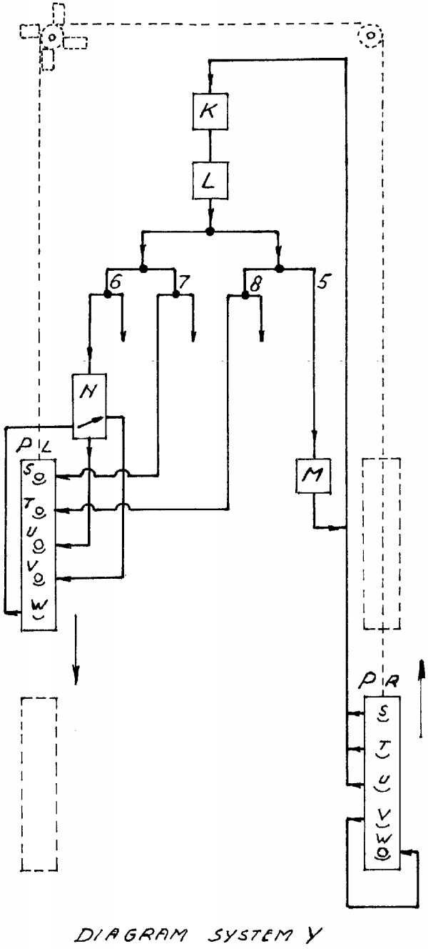
Diagram Y [larger version]
Diagram system Y
K	=	Elevator
L	=	Big wheel
M	=	High speed track
N	=	Tumbler lift
Pl en Pr=	Elevator cages
l	=	Railpoints
Picture L - The Big Wheel
All balls coming out of the Y elevator first go to another big wheel, the same size (1 meter diameter.) as in the X elevator. The wheel has twenty holes. There's a ball in every hole, except one. The wheel is thus unbalanced and wants to turn anti-clockwise, but is caught in a lock. Every incoming ball, before rolling in the empty hole, will push out another ball and release the lock for a moment. This way the wheel will turn 18 degrees each time, just by the weight of the balls.
After passing a whole set of switches the balls go in four different directions (see diagram Y). Direction 5 leads to the high-speed track: a simple free fall of one meter. This gives a ball the highest speed in the entire sculpture. After breaking the speed in a horizontal zigzag track the ball moves to a third disc - the same as in system X - and will finally move on to the elevator.
The sculpture contains two elevator cages (El and Er in the Y-diagram). Each cage is connected to one end of a nylon cord, which runs across guiding wheels. If one cage goes up, the other one goes down. In each cage there are five positions available for a ball. One cage goes down by weight of four balls in the positions S, T, U and V (see diagram). The other cage goes up with only one ball in position W. After having reached the lowest point, the balls are pushed out. The balls S, T and U are going back to the elevator. Ball V will return to the same cage after making some rounds and take up position W. Arriving at the top ball W is pushed out and has to be brought up again, back to position V for the next action. This happens in a tumbler lift by force of the ball coming from direction 2. All incoming balls take, in turns, position in front of the cage. Only the last ball, coming from direction 4, will open the lock. Then all balls enter the cage at the same time and down they go. The open ends in the diagram at switch points 2, 3 and 4 are used for serving the cage elevator in the opposite direction.
09/19/99
The text and drawings on this page are of this document are copyright © 1999 by Piet Reichwein.
This document is licensed for private, noncommercial, nonprofit viewing by individuals on the World Wide Web. Any other use or copying, including but not limited to republication in printed or electronic media, modification or the creation of derivative works, and any use for profit, is prohibited.
This writing is distributed in the hope that it will be useful, but "as-is," without any warranty of any kind, expressed or implied; without even the implied warranty of merchantability or fitness for a particular purpose.
In no event will the author(s) or editor(s) of this document be liable to you or to any other party for damages, including any general, special, incidental or consequential damages arising out of your use of or inability to use this document or the information contained in it, even if you have been advised of the possibility of such damages.
In no event will the author(s) or editor(s) of this document be liable to you or to any other party for any injury, death, disfigurement, or other personal damage arising out of your use of or inability to use this document or the information contained in it, even if you have been advised of the possibility of such injury, death, disfigurement, or other personal damage.
All trademarks or registered trademarks used in this document are the properties of their respective owners and (with the possible exception of any marks owned by the author(s) or editor(s) of this document) are used here for purposes of identification only. A trademark catalog page lists the marks known to be used on these web pages. Please e-mail web@lemur.com if you believe that the recognition of a trademark has been overlooked.
Version
1.3, 1999/09/23.
Feedback to web@lemur.com
http://www.database.com/~lemur/rb-reichwein-essay.html
Go to the: