DMM Varkon® Tutorial
A Beginner's Guide to the Varkon
Parametric Modeling and CAD Application Development System
By David M. MacMillan
If the first local coordinate system established within the BASIC coordinate system has its origin at a constant offset from the BASIC coordinate system's origin in all three axes, then the BASIC coordinate system "follows" this local coordinate system's origin, making the local coordinate system's origin its own origin.
To illustrate this, lets first define an MBS module that draws three axes in the BASIC coordinate system. This module, defined below, is has the BASIC coordinate system attribute. Just to be on the safe side, it also invokes the mode_basic() MBS procedure to ensure that it draws within the BASIC coordinate system.
! vclb.mbs Visible Coordinate Lines in the BASIC coordinate system
!
! Draw 3 axes to illustrate a coordinate system
!
! X = red, Y = green, Z = blue
! (because I'm used to "RGB" in that order and "XYZ" in that order)
basic geometry module vclb(
float delta; ! half-width of the axis line
float axisthickness; ! thickness of the axis lines
int linetype ! LFONT
);
vector xstart, xstop;
vector ystart, ystop;
vector zstart, zstop;
beginmodule
mode_basic (); ! probably redundant; force to BASIC coordinate system
! draw a visible X axis from negative to positive
xstart := vec (-delta, 0, 0);
xstop := vec ( delta, 0, 0);
lin_free(#1, xstart, xstop: PEN=2, WIDTH=axisthickness, LFONT=linetype);
! draw a visible Y axis from negative to positive
ystart := vec (0, -delta, 0);
ystop := vec (0, delta, 0);
lin_free(#2, ystart, ystop: PEN=3, WIDTH=axisthickness, LFONT=linetype);
! draw a visible Z axis from negative to positive
zstart := vec (0, 0, -delta);
zstop := vec (0, 0, delta);
lin_free(#3, zstart, zstop:PEN=4, WIDTH=axisthickness, LFONT=linetype);
endmodule
Now consider the following active module, as typed into the MBS edit window of a running Varkon project.
BASIC GEOMETRY MODULE test3d();
VECTOR neworigin1;
VECTOR neworigin2;
BEGINMODULE
mode_global();
part(#1,vclb(15, 0, 1));
neworigin1:=vec(10, 10, 10);
neworigin2:=vec(10, 0, 0);
csys_1p(#2,"cs1", neworigin1, 0, 0, 30);
csys_1p(#3,"cs2", neworigin2, 0, 0, 45);
ENDMODULE
One would expect this active module first to draw, via vclb(), a visible set of axes centered at the origin of the BASIC coordinate system. It then should establish a new coordinate system, cs1, at an offset within the BASIC coordinate system of (10, 10, 10), rotated 30 degrees around the Z axis. Finally, it should establish another coordinate system, cs2, at an offset of within the BASIC coordinate system of (10, 0, 0), rotated 45 degrees around the Z axis.
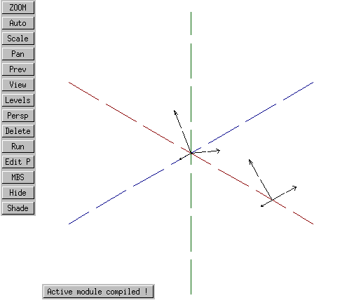
Instead, this happens:

Rather than establishing cs1 at an offset within the BASIC coordinate system, the origin of the BASIC coordinate system is now identical to that of cs1.
However, if we make one change to this active module, setting up cs1 so that one of it's offsets differs from the other two, as follows:
neworigin1:=vec(10, 10, 5);
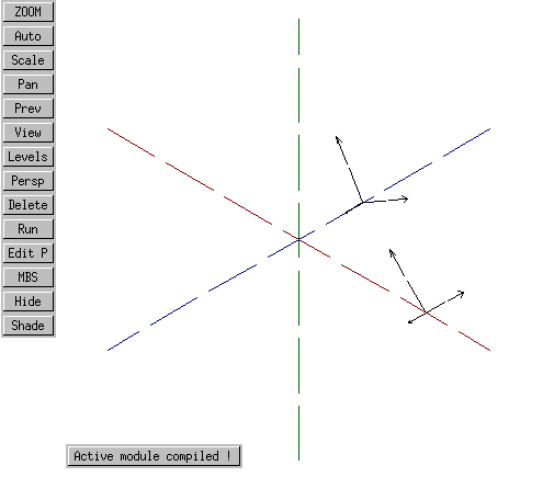
then this happens:

The BASIC origin has followed two of the offsets (the two equal to each other and to 10), but the third offset, being different, has forced an actual offset for cs1.
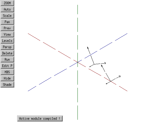
Only when we set all three offsets to different values does the origin of cs1 emerge as fully distinct from that of the BASIC coordinate system. For instance, if we change the active module to specify:
neworigin1:=vec(10, 7, 5);
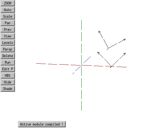
Then this occurs:

Viewed in 115 degree perspective rather than isometric (ISO) perspective, it is clear that the cs1 origin is different in all three planes from the BASIC coordinate system's origin.

I don't know whether this behavior is a bug, a feature, or a misunderstanding on my part.
With the exception of any material noted as being in the public domain, the text, images, and encoding of this document are copyright © 1998 by David M. MacMillan.
The author has no relationship with Microform AB, and this Tutorial is neither a product of nor endorsed by Microform AB.
"Varkon" is a registered trademark of Microform AB, Sweden.
This document is licensed for private, noncommercial, nonprofit viewing by individuals on the World Wide Web. Any other use or copying, including but not limited to republication in printed or electronic media, modification or the creation of derivative works, and any use for profit, is prohibited.
This writing is distributed in the hope that it will be useful, but "as-is," without any warranty of any kind, expressed or implied; without even the implied warranty of merchantability or fitness for a particular purpose.
In no event will the author(s) or editor(s) of this document be liable to you or to any other party for damages, including any general, special, incidental or consequential damages arising out of your use of or inability to use this document or the information contained in it, even if you have been advised of the possibility of such damages.
In no event will the author(s) or editor(s) of this document be liable to you or to any other party for any injury, death, disfigurement, or other personal damage arising out of your use of or inability to use this document or the information contained in it, even if you have been advised of the possibility of such injury, death, disfigurement, or other personal damage.
All trademarks or registered trademarks used in this document are the properties of their respective owners and (with the possible exception of any marks owned by the author(s) or editor(s) of this document) are used here for purposes of identification only. A trademark catalog page lists the marks known to be used on these web pages. Please e-mail dmm@lemur.com if you believe that the recognition of a trademark has been overlooked.
Version
1.3, 1998/06/17.
Feedback to dmm@lemur.com
http://www.database.com/~lemur/vk-bugbasic.html
Go to the: