This Workshop Update will be quite unusual for me: it's about something useful.
In the late 1980s, while helping to clear out a house, I acquired a pair of sawhorses. I don't know when they were made or by whom; they were far from new when I got them. At the time, I didn't think too much about them; they were just nice sawhorses. I did rather like them, though. I've been using them ever since. In fact, they're in use right now supporting a pallet which is acting as a makeshift workbench. Since they cannot do this and be sawhorses at the same time, I needed to build a couple of new sawhorses.
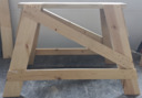
Here's one of my old ones, in its current battered state:
A decade after I got these sawhorses, I ran across a vivid description of an old carpenter making two sawhorses on a jobsite after someone had severely injured themself with a power saw by not using sawhorses. What struck me about this description, aside from the blood, was the statement that every angle on the sawhorses was the same: 75 degrees. Mine were of the same plan (though 13 / 77 degrees, as I discovered).
(See Jeff Taylor, Tools of the Trade (San Francisco, CA: Chronicle Books, 1996.))
Now I understood something about why I liked my sawhorses so much. They had a consistency and conceptual simplicity about them. In my mind, at least, there is a beauty to this sawhorse design which is not found in other designs, however clever they might be.
History and Further Bibliography
I have not been able to trace the origins of this design. The earliest example I've found which resembles it is in a book published by 1918 by Archibald Williams. He called them "Sawing Trestles":

Williams. Things to Make. (Sawing Trestle)
Williams, Archibald. Things to Make. (London: Thomas Nelson and Sons, n.d. [by 1918]). Extract of the chapter on a "Sawing Trestle." Scanned from my copy; public domain.
But Williams' trestles have cross-lap joints. They look back to older woodworking traditions (and surely benches/trestles with splayed legs are as old as woodworking itself). My old sawhorses, and the ones shown in Taylor's book, have a different origin. Their core feature is the long 15 degree (90 - 75 = 15) bevel cut down each side of the top. The end gussets are best made of plywood. These features speak to a 20th century tradition of power tool woodworking.
I have found some more recent references to similar designs.
A basically similar design (differing in details) with a 74 degree angle was shown in a letter by Alvin H. Niemann to the editor of American Woodworker in the Feburary 1997 issue (p. 8). This letter was in response to an article by Paul Anthony in the June 1996 issue of the same magazine, "Advance A-Frame" (p. 49) showing a much more elaborate version with cross-lap joints (called "mortised" in the article) and a shelf.
One of the closest published sources I've found is in an article by Patrick McCombe, "Building Sturdy Sawhorses," in Fine Homebuilding magazine, issue 218. This article was put online on their website in 2011. Its design employs a 17 / 73 degree angle. See: https://www.finehomebuilding.com/2011/03/10/building-sturdy-sawhorses
Ken Collier, in a design from the Family Handyman magazine reprinted on their website, presents a version with a 13 / 77 degree angle (like my old ones) but with tapered legs and two gussets on each end. See: https://www.familyhandyman.com/carpentry/sawhorse-plans/view-all/
Floyd Vogt presents a similar design in Residential Construction Academy: Carpentry (Stamford, CT: Cengage Learning, 2003-2016). It's on p. 241 in the 2003 1st edition. He manages to avoid specifying any angles by converting everything into linear measure. (A preview version of the 1st edition which includes this page is available via Google Books, but the page which should have it is not in the Amazon "look inside" preview of the 4th edition.)
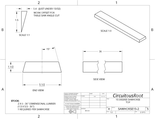
In any case, I decided to work up my own version. I settled on a 15 degree angle because multiples of 5 are easy to set on a table saw. I used a slight end projection (for clamping) as seen in Williams, Niemann, Collier and McCombe, but not Vogt. I'm using stretchers across the bottom (present in McCombe and Anthony, but not Williams, Niemann or Collier).
I've also added an option for cross-bracing. This runs against the grain of traditional woodworking, which relies upon exquisitely crafted joints over the simplicity of good engineering. (Did I write that out loud?) But triangles make a tremendous difference in terms of rigidity, especially as things get old and joints lose their integrity.
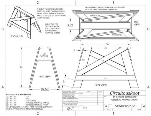
Here's a view of my CAD model, showing the simple version of the crossbraces:
CAD may seem like overkill here. I suspect that the old carpenter in Taylor's Tools of the Trade would have scoffed at my approach, and I can't say that he's wrong. But there are at least two advantages to modeling even this kind of project in CAD. First, you get to make many of your mistakes on (electronic) paper. Second, it makes it pretty easy to generate cut lists (complete with angles). Of course, this only works if you create proper 2-D engineering drawings from the CAD model. Here are two (of the five) sheets of drawings as examples (all five of them, and the model, are linked later in this posting).
The downside of using CAD is that it lulls you into a false precision. The CAD software works without question to many decimal places. Woodworking (and especially carpentry) does not. If the wood is straight, if I'm really careful, and if I pray to St. Roy Underhill, I might be able to work to a scant sixteenth of an inch. But the wood itself can change its dimensions by more than that from winter to summer as the humidity changes. CAD dimensions to the thousandths of an inch just aren't relevant. By the time you get to the cross-braces, you'll just be cutting things to fit anyway.
With this thought in mind, I suggest that you look on the design for the "fancy" version of the crossbraces as a pleasant fantasy in CAD or fine cabinetmaking. It ws fun to model them, and they're pretty to look at - but the simple versions work just as well.
One less tangible advantage of modeling a project with CAD is that it forces you really to see the project. Here's an example: Every version of this design just says (or implies) that you should nail/screw the end gussets flat across the legs. Indeed, in practice you do. So you may never notice that the ends of the legs are not, in fact, in a single plane. Because the legs are angled in two directions, their ends are at a slight angle inward - not perpendicular to the main axis of the sawhorse. I guess it doesn't matter, but I find this kind of thing illuminating. Le bon Dieu est dans le détail.
This is a view of the model from the underside, normal to the bottom edge of one of the gussets. The angle between the gusset (dark blue) and the leg (grey) is highlighted in yellow and its measurement is called out at the bottom right: 3.967 degrees.
There are any number of ways you could make these sawhorses. The old carpenter in Taylor's book made two of them in fifteen minutes with a handheld circular saw. It took me a couple of days and a table saw. I wouldn't last very long on a construction site.
I'll only show a few details here.
Sawhorses naturally come in pairs. You should build at least two. I find it useful to have three. Two are used for most operations. The third comes in handy when I'm ripping the long side off of a 4'x8' sheet of plywood using a handheld circular saw. First clamp the plywood to two of the sawhorses. Start the cut, stop in the middle, put the third sawhorse under the already-cut end to keep it from falling, and then finish the cut. This keeps the piece you're cutting off from twisting off during the last few inches of cutting (and splintering/tearing the plywood as the cut finishes).
I built this during the lockdown phase of the global coronavirus pandemic. Because of this, I used whatever wood was at hand. So I had to make one of my 2x6s from a 2x8. Here's a view of this operation (cutting one of the edge bevels at the same time).
I'm using a sliding-table table saw. This is a derivative of the traditional printers' saw (which originated in the 1890s), although woodworkers and even table saw manufacturers have forgotten this history. (This particular saw is a Grizzly G0700, but they no longer sell this model.) It is the only design of table saw which has any degree of safety inherent in the regular operation of the saw itself, and, having permanently removed the fence, it is the only style of table saw which I will use willingly. But that's a topic for another post.
Here's a shot of the setup for cutting the double bevel at the top (or bottom - they're the same) of one of the legs.
Despite the apparent exactitude of the CAD-derived drawings, I found it best to cut and assemble the top and legs first, before cutting the stretchers or braces. (I then cut these to fit.)
The whole thing is held together with star-drive "construction screws" (I tend to like GRX brand R4 "Multi-Purpose" screws). Phillips screws should not exist aside from a few carefully preserved historical examples in museums - but that's also a topic for another post. For attaching the legs and gussets I drilled pilot holes. For the shorter screws attaching the stretchers and braces I didn't.
Assembling the sawhorses relied heavily upon a tool that, until a short while ago, I never thought I'd own: a "brad nailer." Now I have two. This is the bigger one, a Milwaukee "M18 Fuel" system brad nailer ("fuel" is just marketing-speak; it runs on batteries, not combustible fuel). Since it's a bit of a beast, I've also got a smaller Makita "CXT" system 23 gauge nailer for little stuff. Makita calls theirs a "pin nailer." While the 18 gauge "brads" fired by the Milwaukee unit have tiny heads formed on them, the pins fired by the Makita are entirely headless.
The reason I had avoided these before is that I had not comprehended their purpose. I thought that there was no way that the headless or near-headless brads/pins they fired would hold something together permanently. This is true, but irrelevant. This isn't a tool for permanent construction; it's an aid to assembly. In metalworking terms, think of it as a tack welder for wood.
Consider the joint shown being assembled below. It's easy to clamp the first piece to the bench, but clamping the leg at a compound angle would be trickier. So you have to hold it by hand. Then you need to drill a pilot hole for the screw, change the drill bit for a driver bit (or change drill/drivers if you have two), hold a screw in place against the wood with your other hand and drive it in using the drill/driver you're holding with your other other hand - all without letting the piece of wood slip and misalign the pilot hole. No problem, if you're an octopus. With a brad nailer, you just hold the leg in place and, wham, tack weld it on. Then you can put in the screws using both hands, at your convenience.
The thing about these nailers, though, is that they are potentially very dangerous. The first time you fire an 18 gauge brad nailer it is a bit of a shock. These things can sink a 2 inch piece of wire all the way into solid wood and do it so fast you can't see it happen. (On top of that, the brads/pins don't always go straight in. They follow the grain. I've even had one make a full U-turn. Keep your hands well clear of anywhere the brad/pin might go.) A brad nailer is very useful, but if you are not afraid of this tool then you do not understand it.
I pre-cut the gussets to plan dimensions, but already the combination of my imperfect craftsmanship and the tendency of scrap lumber to morph from Mondrian to Dali resulted in problems of fit of 1/8 inch or more. So much for those four decimal places.
So for the stretchers I marked and cut the boards to fit. (Perhaps remarkably, the 15 degree angle remained intact and I was able to use the same miter setting on my table saw.) For the cross-braces (simplified style) I just cut them by fit and eye.
The results, while certainly lacking in fineness of execution, do have a certain grace of design. I think it may be the 15 degree angle, which to me suggests some Arts & Crafts or Mission Style furniture.
I made three: one in the best available scrap (top right in the photo below), one using 1x6 boards with odd rabbets in them because they were left over from an old project to do ship-lap board paneling in the typefoundry (top left), and one from remaining available scrap (with 1x4 legs because that was what I had left, and one cross-brace in cedar - which of course immediately split). Actually, having one a bit lighter (with 1x4 legs) works out well. It will be the one I use as the outboard support for ripping plywood.
Much to my surprise, two of them sat solidly on the floor without rocking, as-built. On one of them, one leg was short or long by about 1/8 inch. I adjusted this to length with a handheld orbital sander (working outdoors).
They're not lightweight, but they're not so heavy that I can't move them around easily. For a more portable jobsite version you could leave off the cross-braces, the stretchers, or both. If you did this and used 1x4 for the legs, you'd have something very close to my old sawhorses. Leaving the bracing out would also make them easier to carry, one per arm at shoulder level.
As built, as workshop sawhorses, they are satisfyingly solid.
This is open source hardware, so here are the design documents.
I modeled and drew it in the Onshape cloud-based CAD system. At least as of the time of writing, Onshape has a full-function free plan. Here's a link to the Onshape "Document" which contains the model and drawings. I've set its viewing status to "public." I believe that you can view it there even without an Onshape account. In Onshape, you can copy this to your own workspace and modify the copy.
https://cad.onshape.com/documents/5736a42136c292307cb7347f/w/29d1aaacb658d493e9f59b9e/e/0ffdb6b3f9b7bee88ce41c45
(If that link should fail, search Onshape for "sawhorse, 15 degrees".)
If you wish to work with the model in another CAD environment, here are exported versions in Solidworks, STEP, and Parasolid formats:
But really it's the 2-D engineering drawings which are the most useful documents. Here they are in DXF (Release 14) and PDF formats. (The PDFs are the ones to download and print. DXF format requires either a DXF viewer or a CAD package which supports DXF).
The drawings are set up for ANSI A size (i.e. US Letter) paper. If you select a "scale to fit" option when printing them, though, they should print on any paper. Printing with "scale to fit" is fine, because you should be working from dimensions rather than scaling from a drawing anyway. If you print without scaling on a laser printer you may lose a bit around the edges, but with most printers shouldn't lose any real information.
Note, however, that the DXF versions will not display correctly in either Librecad or the "Community Edition" of Qcad.
The model and drawings show the two crossbraces running in opposite directions. When I built the sawhorses, though, I decided to make them both run in the same direction. From the point of view of strength, it makes no difference.
But running the braces in the same direction has the advantage that you could run a board underneath the top on one side. I have no idea why you'd need to do that, but it seems like a good capability to add at zero cost.
One flaw in the current design is that the sawhorses stack poorly. They do stack, but not as closely as they should. Worse, when stacked the extending ends of the table push against the insides of the gussets. This is bound to cause their premature failure.
There are two posible solutions: (1) remove the end "tabs" or extensions to the top, or (2) move/change the gussets. I am unwilling to do the first because even after only a few days of use I'm finding that these extensions are very handy. Here, then, is a possible design for a version with non-interfering gussets. I haven't built it yet.
All portions of this document not noted otherwise are Copyright © 2020, 2022 by David M. MacMillan.
Circuitous Root is a Registered Trademark of David M. MacMillan.
This work is licensed under the Creative Commons "Attribution - ShareAlike" license, version 4.0 International. See http://creativecommons.org/licenses/by-sa/4.0/ for its terms.
Presented originally by Circuitous Root®