The Rolling Ball Web
An Online Compendium of
Rolling Ball Sculptures, Clocks, Etc.
By David M. MacMillan et. al.
The following two sequences of photographs show the operation
of an Arrow Mfg. Co. rolling ball display clock during one complete
cycle of the 1-minute tilting arm
(from 1:04 to 1:06)
and through the operation of the delaying of the 5-minute arm's
ball stream.
They were taken in December 1997
on the dining room table,
with the clock propped up on
some phone books covered with a dark blue towel.
An old manual camera was used, on a cheap tripod,
with no flash, a half-second exposure,
200 speed film,
and a bunch of shop lights shining on the clock.
These are by no means photographs of professional quality.
They do, however, more or less show the operation of the clock.
The clock is black plastic,
and its clear plastic protective cover has been removed.
If possible, please resize your web browser's window so that
the full width of these images is visible.
Note: Some web browsers do not display images with full fidelity.
For best image quality, save these images to temporary files
and view them with an offline image viewing program.
Please note that even when saved to files
the licensing terms and the disclaimers stated in the
Legal Matters section of this document still
apply to these images.
(26 photos, approximately 264 kilobytes total)
 |
 |
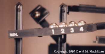
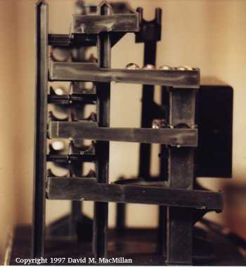
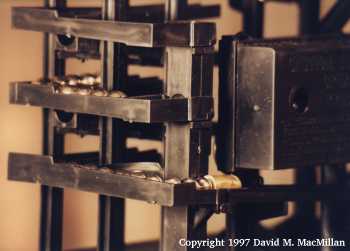
1. The time is 1:04.
The 1:05 ball is being elevated by the rotating arm. |
2. The ball falls out of the cradle
on the rotating arm onto the top track.
(The ball is held in place here with tape.) |
 |
 |
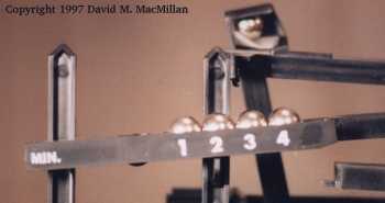
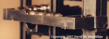
| 3. The ball
begins its roll down the top track. |
4. Having rolled all the way to the
right on the top track,
the ball rolls back to the left. |
 |
 |
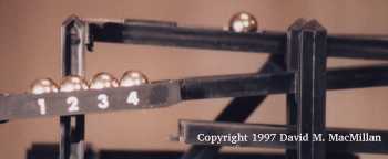
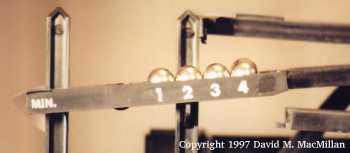
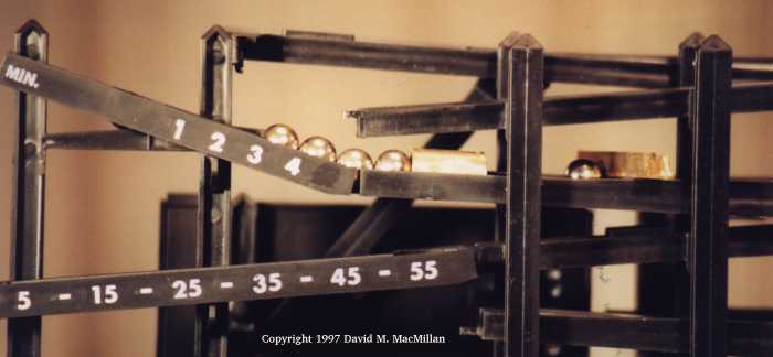
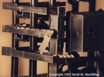
| 5. The ball
reaches the tiltable 1-minute arm
(it is just visible behind the 4 ball).
The arm is being held in the "up" position with tape at
the left; the arrival of the 5-minute ball has
weighted it so that it wants to tilt down to the right. |
6. This is a top view of the 1-minute arm
with all balls removed.
The circular hole on the left holds a non-rolling, dark colored
ball added to counterweight the arm.
All balls enter the arm through the short channel to the top right.
The 1 through 4-minute balls accumulate in the long,
front (lower in this view) channel in the arm.
The 5-minute ball enters the arm, but is prevented from
going into the 1-4 ball channel by the 4th ball.
The 5-minute ball thus stays (briefly, until the arm tilts)
in the short entry channel.
When the arm tilts, the 1 through 4-minute balls exit
straight to the right from the front channel
(lower in this view) and enter a ball-return track.
The 5-minute ball exits straight to the right from
the rear channel and goes to the 5-minute arm.
|
 |
 |
| 7. This is a view of the 1-minute
arm from the left, showing it empty, in the "up" position.
The non-rolling weight ball is present.
|
8. This is another view of the
1-minute arm in the up position, taken from the right.
The entry path is clearly visible, as is the exit path at the
front for the 1 through 4-minute balls.
With some imagination to compensate for my out of focus photo,
the exit path at the rear for the 5-minute ball may be
discerned.
|
 |
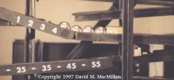
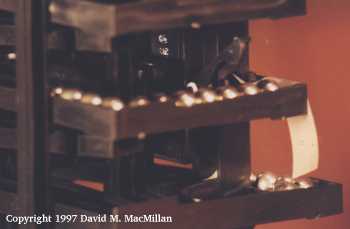
| 9. The 1-minute arm has just
tilted, releasing its balls.
The 1 through 4-minute balls are rolling into a track at the
front of the clock which will lead them back to the ball supply;
they take no further part in the time-displaying function.
(They are being held in place in the photo by a small cylinder
of brass blocking their path.)
The 5-minute ball is rolling into a short track just behind this;
this track is not itself visible in the photo.
This ball will proceed on to the 5-minute arm and indicate,
by its presence there, that five minutes have passed.
(This ball is being held in place in the photo by a short
length of scrap brass placed across its path.)
|
 |
 |
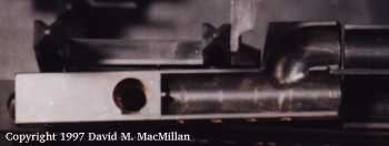
10. The 5-minute ball has just
dropped down through a hole in its exit track to a track below;
it will follow this lower track into the 5-minute arm.
Unfortunately, in this photo the 5-minute ball is very dark.
It is barely visible on the right, being blocked by a piece
of scrap brass.
The 1 through 4-minute balls are still being blocked in
much the same position that they were in in the previous photo.
|
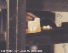
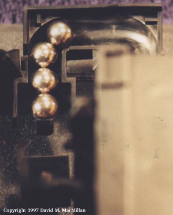
11. This is a detail of photo 10,
showing the 5-minute ball more clearly.
|
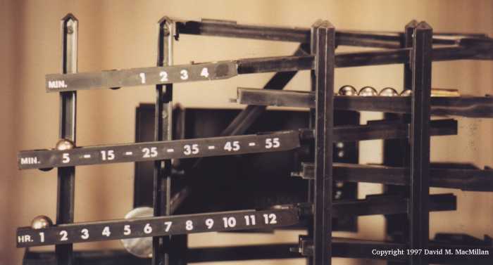 |
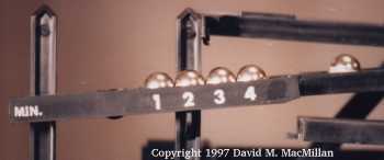
12. The
5-minute ball has rolled into the 5-minute arm.
The 1 through 4-minute balls are moving to the right
along their exit track.
The 1-minute arm has returned to its "up" rest position.
The time is 1:05.
Note that the 1-hour ball is fixed in the 1-hour arm and
never rolls. When you count the hours from 1 to 12,
it is always at least 1 o'clock (never zero o'clock).
|
 |
 |
| 13. The 1 through 4-minute
balls roll to the right of the clock on their way back
to the ball supply.
Here they are shown just before they enter the
hollow vertical tower at the right rear of the clock.
|
14. Here they are shown
after they exit the tower at the level of the bottom
track.
Upon leaving the tower, they roll through a short L shaped
track and merge with the lower track itself.
|
 |
| 15. All balls, once
on the lowest exit track, roll down the back of the clock
and collect.
Here they are being held in place just short of their final
destination by the ubiquitous brass cylinder.
|
 |
 |
| 16. Here the balls are
at the end of their downward journey.
The leading ball is in position to be picked up by the
rotating arm as the next minute passes.
|
17. The rotating arm then
picks up the leading ball.
|
 |
 |
| 18. This is a closer view
of the ball being picked up.
|
19. The rotating arm elevates
the ball back to the level of the top track.
|
 |
Imagine photo 2 above,
but with an empty 1-minute arm.
|
| 20. This is a view from a lower
angle of the rotating arm in the same position as the
previous photo, elevating a ball.
|
21. Then the ball drops off of
the rotating arm and into the top track.
The time is 1:06.
|
The principle illustrated above is also used in both the
5-minute arm and the 1-hour arm.
Throughout the hour, a new ball enters the 5-minute arm every 5 minutes.
This continues until until there are 11 balls in this arm,
signifying 55 minutes.
When the 12th ball enters this arm at 60 minutes past the hour,
its weight tilts the 5-minute arm.
The first 11 balls exit to the right and return to the ball supply.
The 12th ball, like the 5th ball on the 1-minute arm as described above,
exits on a different path, falls through a hole in that path, and
enters the 1-hour arm.
The 1-hour arm accumulates the hours, in the same manner.
It is unusual in that the 1 o'clock ball is fixed in the same
position (by a small barrier molded into the track).
As noted above, when you count the hours from 1 to 12,
it is always at least 1 o'clock (never zero o'clock).
There remains one other, rather subtle, issue with this design.
As all three ball exit paths ultimately converge,
there is the possibility that when two or more tilting arms
discharge roughly at the same time that their discharged
ball streams will collide.
This would clog the ball return path and the clock would
run out of balls within several minutes.
To prevent this, the clock interrupts the ball stream from
the 5-minute path until about 15 seconds after the hour,
giving the balls from the other paths time to clear.
It is only necessary to block the 5-minute ball stream path
because the the 1-minute and 1-hour ball
streams do not interfere with each other.
The 1-minute ball stream, as it is short and is triggered first,
easily clears the exit path before the 1-hour ball stream
is released.
The photo sequence below illustrates this process of delaying the
5-minute arm ball stream.
 |
 |
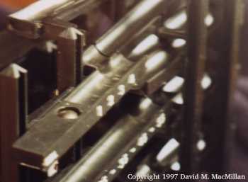
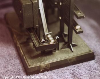
1. The time is a few seconds
after 1:00.
The excess balls from the 1-minute arm have already
gone completely through the exit path.
The excess balls from the 5-minute arm have discharged
and are being held in place on their exit path,
before their entry into the exit tower,
by a small tilting arm which blocks their exit path.
This arm is so weighted that it is normally down,
blocking the exit path.
The excess balls from the 1-hour arm have also discharged.
They are being held in their exit path artificially,
for the purposes of this photo, by a small brass cylinder.
If the 5-minute ball stream had not been blocked as shown here,
it would have collided with the 1-hour ball stream
on the lower exit path.
|
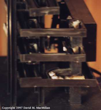
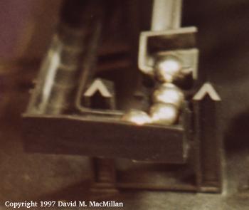
2. This is a closer view
of the 5-minute balls being held.
|
 |
 |
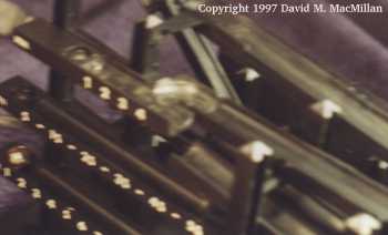
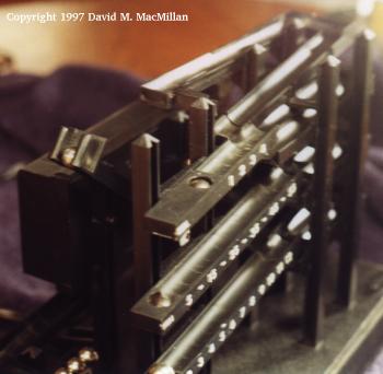
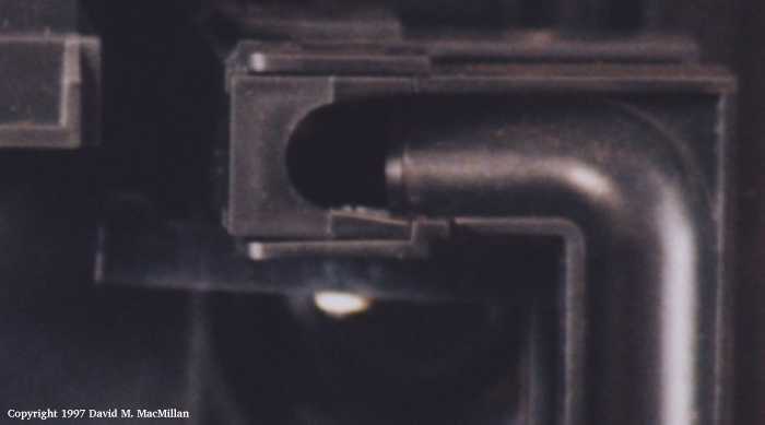
| 3. The holding arm is raised
by the main rotating arm of the clock as it swings by at
about 15 seconds after the hour.
In this photo, the arm has been raised and the stream
of 5-minute balls is beginning to roll onward.
(They are being restrained here by a rather crudely applied
piece of tape.)
By this time, the 1-hour ball stream has cleared the point
where the 5-minute and 1-hour exit paths join.
(There should actually be eleven balls in this stream rather than
the five shown here, but I got tired of putting little
ball bearings on tracks.)
|
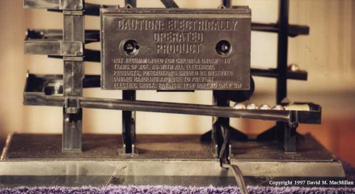
4. Here's a view of the same
situation from a different angle.
|
 |
| 5. Here, the 5-minute balls
have continued through the vertical exit tower and are
now on the lower exit path.
|
 |
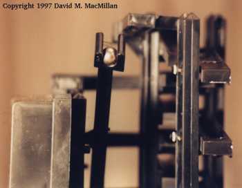
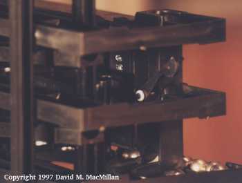
| 6. This is a very dark
view from above, looking down onto the vertical exit
tower.
The holding arm is the slightly ghostlike horizontal object
just below the square tower in this view.
The bright spot is its hinge. The main rotating arm
pushes this small holding arm down to the left of this hinge,
thus releasing the 5-minute ball stream.
|
It should be noted that this holding arm goes through its
motions every minute (every rotation of the main ball-lifting arm).
59 times out of 60, this motion accomplishes nothing as there
are no 5-minute arm balls to block.
Legal Matters
With the exception of any material noted as being in the public domain,
the text, images, and encoding
of this document are copyright ©
1997-1998
by David M. MacMillan.
This document is licensed for private, noncommercial, nonprofit
viewing by individuals on the World Wide Web.
Any other use or copying, including but not limited to
republication in printed or electronic media,
modification or the creation of derivative works,
and any use for profit,
is prohibited.
This writing is distributed in the hope that it will be useful,
but "as-is," without any warranty of any kind, expressed or implied;
without even the implied warranty of
merchantability or fitness for a particular purpose.
In no event will the author(s) or editor(s) of this document
be liable to you or to any other party for damages,
including any general, special, incidental or consequential damages
arising out of your use of or inability to use this
document or the information contained in it,
even if you have been advised of the possibility of such damages.
In no event will the author(s) or editor(s) of this document
be liable to you or to any other party for any injury, death,
disfigurement, or other personal damage arising out of your use of
or inability to use this document or the information
contained in it, even if you have been advised of the
possibility of such injury, death, disfigurement, or other
personal damage.
All trademarks or registered trademarks used in this document
are the properties of their respective owners and
(with the possible exception of any marks owned by the
author(s) or editor(s) of this document)
are used here for purposes of identification only.
A trademark catalog page
lists the marks known to be used on these web pages.
Please e-mail
dmm@lemur.com
if you believe that the recognition of a trademark has been overlooked.
Version
1.8, 1998/06/18.
Feedback to dmm@lemur.com
http://www.database.com/~lemur/rbc-arrow-op.html
Go to the: