The Rolling Ball Web
An Online Compendium of
Rolling Ball Sculptures, Clocks, Etc.
By David M. MacMillan et. al.
This WWW page contains a transcription in HTML of the Specification, No. 3164, of Sir William Congreve's patent of 1808 entitled "A New Principle of Measuring Time and Constructing Clocks and Chronometers." This principle, referred to by Congreve as that of "extreme detachment," is in this Specification incorporated into several devices, including Congreve's famous tilting inclined plane rolling ball clock.
(7 images, approximately 214.7 kilobytes total.)
Please see the Legal Matters section for a discussion of copyright, licensing, and source information.
This transcription was done by hand and may contain errors. Please notify me at dmm@lemur.com if you discover any.
This document should have been encoded using the Text Encoding Initiative's DTD ("the TEI") rather than directly in the HTML DTD. Unfortunately, at the time of encoding no TEI to HTML translator was available.
Note that some WWW browsers can create visual artifacts, such as stippling, in images. For the best display of the images contained here, save them to a file and view them offline with the image viewer of your choice.
To all to whom these presents shall come, I, William Congreve, of Garden Court, in the Temple, in the County of Middlesex, Esquire, send greeting.
Whereas His most Excellent Majesty King George the Third did, by His Letters Patent under the Great Seal of the United Kingdom of Great Britain and Ireland, bearing the date at Westminster, the Twenty-fourth day of August, in the forty-eighth year of His reign, give and grant unto me, the said William Congreve, my executors, administrators, and assigns, His especial license, full power, sole privilege and authority, that I, the said William Congreve, my executors, administrators, and assigns, during the term of years therein mentioned, should and lawfully might make, use, exercise, and vend, within England, Wales, and the Town of Berwick-upon-Tweed, my Invention of "A New Principle of Measuring Time and Constructing Clocks and Chronometers;" in which said Letters Patent there is contained a proviso obliging me, the said William Congreve, by an instrument in writing under my hand and seal, to cause a particular description of the nature of my said Invention, and in what manner the same is to be performed, to be inrolled in His Majesty's High Court of Chancery within one calendar month after the date of the said recited Letters Patent, as in and by the same (relation being therunto had) may more fully and at large appear.
Now know ye, that in compliance with the said proviso, I, the said William Congreve, do declare that my said Invention is described in manner following (that is to say):-
The new principle or system of measuring time and constructing clocks and chronometers, which is the basis of this Patent, is founded on certain modes herein-after specified, of detaching the time measurer from the first mover for an extent of duration far beyond anything ever yet effected or proposed, and which is not confied within the limits of ordinary detachments. Thus the only detachments hitherto effected have either been limited to a period somewhat less than the smallest portion of time indicated by the vibrations of their time measurer, and have therefore seldom been extended beyond seconds, or they have been effected by the intervention of an auxiliary power between the first mover and the time measurer, which indeed ought scarcely to be considered as falling within the class of detached movements, as the time measurer, when discharged from the maintaining power, is in this case still combined with another force. But by the system here specified the duration of the detachment of the time measurer from the first mover may, without the intervention of any intermediate power, be extended to a period comprehending any number of the smaller portions of time indicated by the time measurer; in other words, the time measurer shall indicate seconds or any smaller division, and yet it shall be absolutely detached from the maintaining power for a period of one or more minutes. This, therefore, gives a most distinct and definable character to this new mode of measuring time, the leading property of which is a new and extremely extended detachment, and which I have therefore denominated the "mode of extreme detachment."
Before I proceed, however, to the several plans for effecting it, I shall briefly state its principle advantages. The great difficulty of combining the actions of the regulating principle of clocks with the maintaining power, so that the regulating organ whall be operated upon freely and uniformly by the action of gravity, whether accelerated or retarded by the non-accordance of the first mover, has long since pointed out that the only true system of effecting this desideratum was by detaching them as much as possible rather than by combination with the ordinary regulators, that is to say, with the common pendulum or balance wheel. The extent of this principle of detachment, as already observed, is extremely limited; for as, with the most perfect detached escapement in use, the maintaining power is allowed to act on the pendulum for a certain portion of every oscillation, it follows that with the common pendulum it would be extremely inconvenient to detach the first power for an interval much longer than a second, in so high a law to the lengths of pendulums increase as their times, so that to obtain a detachment of 2" would require a pendulum of 13 feet 0.512 inches in length; to obtain one of a minute would require no less a length than 11738 feet 4.800 inches. The first, therefore, which would still be very limited as to any important correction in its effect, would be of a most inconvenient, and the latter of an impossible, length. By adopting the mode of this Patent, however, it will be found that such, or even a greater, extension of detachment than a minute is practicable without any difficulty or inconvenience whatever, and even in a smaller space than is required for the common seconds clock. The next general advantage is, that a clock made on the principle of extreme detachment requires much less first power than a common clock, for the power of the former may be organized so as to rest altogether for intervals of minutes, and to be limited when in action to less than half seconds between those intervals, while that of the latter is constantly exerted every second; nevertheless the maintaining power of the former need not have more to perform every minute than the other has every second. It follows, therefore, that a clock may be constructed on this principle to require only one sixtieth of the weight or power of a common clock, or, that with the same power, it will go sixty times as long. Again, the mode of extreme detachment, by diminishing the quantity of the first force to so great a degree, and by the constant state of repose which it preserves in the train of the clock, removes almost entirely the strain and friction to which the works of a common clock are subject, so that the wear of the patent clock becomes next to nothing, and it can therefore scarcely ever require the application of oil, or get out of order. So also this system of detachment will be found greatly to simplify the train; in fact, the greater the extent of the detachment the more simple will it be by working from minutes or other longer times instead of seconds; notwithstanding which, however, the second or any less division of time, may be indicated with as much accuracy as in the more complicated train of the common timepiece. Such then are the general advantages of this Patent, and whether they be viewed with reference to the extent of the detachment or the diminution of the maintaining power required, or the simplification of the train, I conceive that no further discussion of the principle is necessary with those who are at all conversant with the principles of timekeeping, to convince them that the attainment of these points is of the utmost importance to the final perfection of a true measure of time.
I shall therefore now proceed to the Specification of the plan which I have practised for their accomplishment. And here I have introduced a new modification of the action of gravity as applied to timekeeping, by taking, as the time measurer, "a perfectly detached body descending freely down an inclined plane;" which modification, although it has never yet been applied to the measurement of time, is as immutable in its operation as the oscillations of a pendulum, and is, in fact, governed by the same law; the extreme detachment of which it is capable, and certain specific advantages which the pendulum does not possess, have pointed it out to me as an important agent in the measurement of time. The following are several different modes in which I have applied this new regulating organ for the accomplishment of this Patent: -
Figure 1:
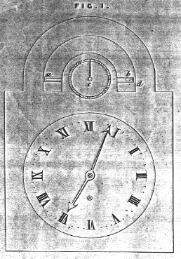
Figure 2:
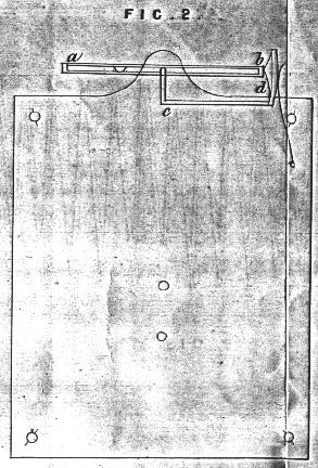
Fig. 1 and 2 shew the dial and frame plate of an eight-day spring clock, having a small tube a, b, six inches long, containing a steel ball. This tube and ball serve the purpose of a pendulum 7 feet 4.038 inches in length, making exactly forty beats in a minute. The tube is connected with the train merely by an arbor and pinion, and being a little inclined, the ball runs from a to b, where it discharges by striking against it a small spring detent d that holds the tube in the position a, b, when, being so discharged, the tube makes a half revolution from b to d, and is caught again by the same detent, the ball being thus brought back to the upper end, runs down again, and striking the detent, repeats its half revolution as before. This tube may be in part considered as a revolving pendulum, where the centre of gravity oscillates but the system revolves, and where the time is measured, partly by an oscillation, and partly by the descent of the ball down the plane. The clock is at rest while the ball runs from a to b, that is, two thirds of the whole time; and a tube of six inches, thus producing beats as slow as a common pendulum 7 feet 4.038 inches in length, is consequently in that proportion so much less liable to the expansions or contractions of temperature. All the escapement work is also here avoided, a common steel pinion being substituted for it, the effect of the escapement being produced by the descent of the ball. This property, peculiar to the new regulating organ here required, is undoubtedly a very important one, from the great nicety required in the construction of escapements, and the comparative simplicity of making a common pinion, which here answers all the purpose. The time is regulated by the small hand at C, Fig. 1 and 2, which, by moving the detent d higher or lower, diminishes or increases the inclination of the tube, and with it the time of descent.
[There is no paragraph break in the original document at this point; Figure 3 is inserted at this point in this transcription for ease of reference.]
Figure 3:
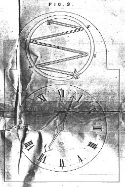
Fig. 3 is the face of a clock similar to Fig. 1, but having a small wheel a, b, instead of the tube connected with the train by an axis and pinion as before; this wheel contains a series of inclined planes a, x, y, z, u, b which, being held in a given position by a small spring detent d, as in the former case, the ball unlocks the wheel, and the time is regulated as above. In this application six seconds are consumed in the running of the ball from a to b, and in the shifting of the wheel half round for a fresh run of the ball. This index, therefore, makes ten beats in a minute, or five whole revolutions; and, the wheel not occupying more than half a second in shifting, the first mover and train are at rest eleven-twelfths of the whole time, during which proportion of time the regulating organ is entirely detached from the maintaining power, and thus the detachment is carried to as great an extent as, by means of the best detached escapement hitherto made, it could be made with a common pendulum of 116 feet 8.608 inches in length.
[There is no paragraph break in the original document at this point; Figures 4 and 5 are inserted at this point in this transcription for ease of reference.]
Figure 4:
Figure 5:
Fig. 4 is a clock in which the detachment is carried to a still greater extent. a, b, Fig. 4, is an inclined plane fourteen inches long and eight inches wide, having thirty grooves cut in it, as shewn in plan Fig. 5; along these grooves a small ball runs from a to b, or from c to d, according as the plane is inclined one way or the other. Now this plane is calculated at a certain inclination to give exactly one minute for the time of the ball's motion from one end of it to the other, where, having arrived at the lowest point, it strikes a lever n connected with the detent e, and unlocking it the maintaining power is allowed to act for a moment for the purpose of shifting the plane (which is most accurately balanced on a knife edge) into the position c, d, that the ball may run back again in another minute to the opposite extremeity of the plane, where it again unlocks the same detent by a corresponding lever m connected with it. The velocity of the ball is no greater at the bottom of the plane than at the end of the first groove, for the acceleration required in each groove is destroyed by the small brass deflectors z, z, z, z, &c., Fig. 5, at the end of each groove, which turn the ball into the opposite direction of each succeeding groove; neither is the ball allowed to stop the least instant of time during the shifting of the plane, but is immediately thrown back on its return by the action of a small crooked arm so regulated by its form and pressure as instantly upon the ball's striking the lever to throw it back, and keep it moving on its rturn until the shifting of the plane is completed with the mean velocity of its motion on the plane when so shifted, so that no inequality produced by the first power in the time of the planes shifting can make any variation in the whole time of the ball's motion from one end of the plane to the other, for, whether the plane rises faster or slower, the ball always returns at the same rate without a moment's pause. This correction is indeed almost superfluous, for in the very short and rare action of the maintaining power, during the almost instantatneous shifting of the plane once a minute only, any inequality that can possibly arise with ordinary good workmanship must be next to nothing, and can hardly produce a sensible effect in the longest period of going. It shews, however, that the principle of extreme detachment may in this application be made absolutely perfect, inasmuch as neither the motion of the ball in its progress along the plane, nor at the moment of its departure on its return, is in the least influenced by the first mover; the time of shifting the plane is not so much as half a second, therefore the first power of this clock is at rest, and the whole train in a state of repose more than one hundred and nineteen hundred and twentieths of the whole minute; that is to say, all connection with the moving power is as long suspended as could be effected, on the ordinary principles of detachment, with a pendulum of the enormous and impossible length of 11,783 feet 4.800 inches, which, if it were practicable, would vibrate minutes; yet, notwithstanding this extreme detachment in the patent clock, the smallest portion of the intermediate time may be indicated by the beats of the ball or time measurer, which, as stated at the commencement of this Specification, is the great characteristic of this new mode of detachment. This is effected by a bridge or bridges, &c. f, f, across the plane, under the arches of which the ball passes. The figures indicating the division of time, thus shewn, are made to shift accordingly as the ball runs from right to left or from left to right, so that they may be read off in seconds or smaller divisions with the greatest accuracy, as the motion of the ball is nearly uniform, all acceleration in passing down the plane being destroyed, as already described, at the end of each groove. To explain the remaining parts of this clock, the circle M shews the minutes advancing one every time the plane shifts, and the minutes being driven directly from the moving power P, the circle H shews the hours which are driven from M. R is the regulator, being the means of connection between M, the minute hand, and the plane, which is effected by a crank and rod x, y. Every time, therefore, the ball unlocks the plane, R is allowed to make half a revolution, which gives the time to both minute and hour hands; the circle R therefore is graduated, and has a hand which adjusts the distance of the crank from the centre of the circle, by which adjustment of the inclination of the plane is varied, and with it the time. Thus, in the space of a moderately-sized table clock, a timepiece is constructed, the vibrations of the regulating organ of which are as slow as those of a pendulum 11,738 feet 4.800 inches in length, by which the first power is so reversed that the weight or spring of a common eight-day clock may be made to carry it four hundred and eighty days; neither is there any friction or motion in its train for one hundred and nineteen hundred and twentieths of the whole time of its going, while the train itself is also considerably more simple than that of a common seconds clock.
It is evident that there are innumerable varieties of configuration in the application of this principle, which it is impossible to specify or even to anticipate, but which must nevertheless be integral parts of this Invention, if they in any shape accomplish the mode of measuring time by means of the extreme detachment here specified. To attain this, therefore, it cannot be lawful for any one to make use of any body, whether spherical, cylindrical, or conical, moving on any inclined plane, however the same may be combined with any machinery or clockwork wahtsoever, whether the plane be simple or complex, curvilinear or rectilinear, whether it vibrate or revolve, whether the body moving down it be a simple or compound substance consisting of one or more parts, whether it be a fluid or a solid, or a combination of both. Various modes also may be introduced for the compensation of the expansions and contractions of temperature, either in the detent or in the rod x, y, which it is not necessary here to specify; but it should be observed, that an inherent power of compensation is combined in the very principle itself, for as the plane expands so also does the ball, and vie versâ; the ball therefore moves quicker as its course is lengthened, and slower as it is shortened, because the vertical distance of the points of contact from the centre of gravity of the ball increases with the expansion and decreases with the contraction of the ball and plane, so as to accelerate the motion of the ball in the first case and retard it in the second. It appears, therefore, that this inherent property may be a due proportioning of the diameter of the ball, and the matter of which it is formed, to the mean length of the plane, and its component materials be so adjusted as of itself to produce a perfect compensation. And lastly, with respect to the workmanship of clocks made on this principle, it appears that less attention to it is required than in common clocks; for as to the train it has so little comparatively to perform, and so little of the measure of time has been shewn to depend upon it, that any want of superior workmanship must be little felt, and for ordinary purposes, therefore, even less than ordinary accuracy must be sufficient. And as to the plane, as any inequality in the surface or irregularity in the first formation of the grooves, must always similarly recur to the ball in every descent, it follows that no such circumstances can destroy its true measure of time; but should any change in the surface of the plane or in the form of the ball take place in a length of time, such change must be for the better, since the edges of the grooves will become more and more even and polished as the ball travels, and the ball will wear itself into the most perfect sphericity, as from its rolling over at the extremity of each groove by means of the deflectors z, z, z, Fig. 5, its axis of motion is constantly varying. It appears, therefore, that no part of the truth of the action of such a clock depends, as is the case with the present system of good timekeepers, upon the exquisite perfection of their workmanship, neither does it depend upon any particularly nice adjustment or preservation of position; for although the clock be placed out of the true level, so that the plane in shifting becomes more inclined one way than the other, still it will be found that what the ball has gained one way it will exactly lose the other, and that therefore the result of every two librations of the plane must (in any position in which the ball will continue its motion both ways) be the true measure of the sum of any two consequent periods of its course, a principle of self-correction which does not exist in common pendulum clocks.
Figure 6:
The next application of this new modification of the power of gravity for the measurement of time which I propose to specify is that in which two balls are used instead of one, as in the cases hitherto explained. A, B, C, Fig. 6, is a wheel attached to the train of the clock by an axis and pinion similar to that in Fig. 3, having three tubes, A, B, B, C, and C, A, and two balls. Suppose the two balls at 1 and 2, then will the wheel oscillate slowly till the balls are brought nearly into the position 2 and 3, by the simple operation of travity, and suppose that at this point the first mover is allowed to act for an instant to throw the wheel a little further round, so that the upper tube becomes in a small degree inclined, that ball will then run to the other extremity, so as to restore the first position 1 and 2, which change will immediately produce another slow and detached movement of the wheel nearly one third round, and this being compleated, as before, the first position will again be assumed. This variation, therefore, though depending upon the action of two balls instead of one, must be considered as another integral part of this Patent, not only because it acts by a similar process, but because it produces the same effect. It cannot therefore be lawful for any one to construct a clock, the time measurer or regulating organ of which shall be constructed by means of this or any similar application of two or any greater number of balls, whether they act by partial revolution or oscillation, or however they may be connected with each other or with the train, and it is evident that no possible application of the descent of any body or bodies fluid or compound down an inclined plane can be made for the purpose of measuring time or of procuring the system herein specified of extreme detachment between powr which must not be a violation of this Patent.
Figure 7:
I shall now therefore proceed to specify the mode by which I accomplish precisely the same system of measuring time by the simple pendulum; that is to say, where, agreeably to the characteristic distinction which pervades this Patent, the duration of the detachment shall not, as by the present system, be limited to the times of vibration, but on the contrary, let a pendulum vibrate half seconds, quarter seconds, or any smaller portion of time, still, like the ball on the inclined plane, it shall be absolutely detached from the first mover for any number of these portions, as a minute or any number of minutes, and this also without the intervention of any intermediate or auxiliary power. Fig. 7. A is a light spring wheel with thirty teeth unconnected with everything but the seconds hand and the small pair of pallets X, Y, which by an inverted action drive the wheel. B, B, is a large swing wheel having sixty teeth connected with a single pallet P on the same stock as those X, Y; P being driven by the wheel B, B. C a wheel of sixty teeth on the same arbor as B, being the last wheel of the train, or effected, if preferred, by sixty steel pins on the face of B. E,F, a lever locking the wheels C and B by the pressure of spring S, except when discharged by the pin p on the face of A. D, centre of suspension of the pendulum. Now suppose the wheels C and B locked by E, F, in such a position that the pallet P works within the teeth of B, without touching either way, and suppose a seconds pendulum set in action under these circumstances; then will the force of oscillation given to it drive the small wheel round by means of the pallets X, Y, with a dead beat indicating seconds at every vibration, so as to make the seconds hand revolve once in 60''. At the 60th second the pin p will come into contact with the lever E, F, and unlock B, which has remained in a state of repose for 59'', during which time the pallet P has had no connection with the swing wheel B, and the pendulum has vibrated perfectly free and detached from the moving power. On being unlocked, however, as above described, the wheel B starts forward by the action of the first mover, and, encountering the pallet P, gives it an impulse regulated to restore the oscillating power lost by the pendulum during the 59 vibrations of seconds; at the end of the 60'' second, however, the pin p has escaped the lever E, F, and the wheels C and B are again locked so as to allow of 59 more free vibrations of the pendulum until the pin p comes round at the 60'' to release them again. Thus then there is obtained by the common pendulum a perfect and extreme detachment for 59'' of the minute, and it is evident that the principle may be extended by increasing the numbers to any greater degree within the limits of the inherent and detached oscillating force of which the pendulum can be made capable without increasing the time of the oscillation, and also without introducing any auxiliary force between the first mover and the regulator, contrary, as before stated, to the properties of every escapement yet applied. I shall now, therefore, compare the advantages of this mode with the present system of detached escapements.
In the first place the description of its action shews how much more the detachment is extended, and how much more the pendulum, as the regulating organ, is in the case left to the pure and unmixed action of gravity. In no escapement hitherto constructed has the pendulum a perfect freedom of oscillation, even for a single second, without having at some point or other to unlock some detent or perform some similar operation, which immediately brings upon it a controlling power in a direction contrary to its spontaneous effort, or an accelerating power to urge it forward, and which from the infinite nicety of application required must, from its constant interference, continually tend to effect the isochronism of the pendulum. Here, on the contrary, for 59'' the gravity of the pendulum is the sole and uncontrolled cause of its motion, having its arcs of vibration neither lengthened nor shortened by any urging or opposing cause, for the mere driving of the light and perfectly free second hand, constant, uniform, equally poised, and opposing no limit to the arcs of vibration, can be considered as nothing but a small increase in the frictino on the point of suspension until the 60'' second when it has to unlock the detent, and when at the same instant it receives a fresh supply of force, left, however, to operate as freely as before in the production of its effect upon 59 out of 60 of the subsequent oscillations of the pendulum.
In the second place, it will be found that considerably less first power is required to keep the same pendulum in action for a given time by this mode, because one great impulse will be found to be given with much less absolute friction than the sum of a great number of small forces, even if they amount to the same impulse; for as many parts (and even more) of the train are in motion, and in as much motion each to produce the lesser impulse as the greater one, and therefore in giving the one united impulse there is no more friction than in giving each of the sixty lesser ones; that is to say, the friction in applying the requisite maintaining power on this principle is only one sixtieth of what it is in the ordinary mode. But this is not all, for a pendulum thus allowed to act freely would maintain the force of vibration first given it for a much longer time and with much less variation in its arcs of oscillation than when coming constantly in contact with machinery, supposing no such power given; therefore, although that machinery may constantly impart to the pendulum fresh increments of force, still, in doing so it follows that by the very contact of machinery necessary for imparting this new force, a certain part of the inherent force at the time of contact is destroyed at every such contact, which were it no so acted upon would continue with little variation for considerable periods. To withold this contact as long as possible is therefore a direct saving of all this force for the time of such detachment; nor is there more of this inherent force destroyed in the contact necessary to give the one impulse every minute (or whatever the period may be) than would be lost in giving the divided impulses of each second; for the power required to unlock the detent, in one individual action at the end of the minute, is no more than in the other individual actions at the end of each second; nor is the friction in the one individual action of the pallet at the end of the minute more than in the other individual action of the end of each second. Here then is a saving of the inherent force of the pendulum in a ratio of 59 to 1, to be added to the saving of friction above stated to be also in that same ratio. Now these will be found to be the principal causes of that loss of motion in the vibrations of pendulums, which is to be restored by the first power, for the remaining causes of its loss of motion are but the friction on the point of suspension and the resistance of the air; on these two there certainly will be always an increase of efford required in the impulse of the maintaining power in the direct proportion of the length of time they are allowed to accumulate; but as these latter are extremely trifling compared to the other two causes of the loss of power above mentioned, in which there is an absolute gain of 59 to 1, it follows, that although the saving of power, on the whole, will not be exactly as 59 to 1, still it will be nearly so. To calculate it exactly is not, perhaps, possible, because it is difficult to say what the proportion of the friction of the point of suspension in the pendulum is to that of the whole work, and indeed it may not be the same in any two clocks, but is evidently, under any circumstances, an extremely small part of the whole.
In the third place, this application of the system of extreme detachment has all the advantages of increasing the time of repose, as to the wear of the work, in common with the inclined plane regulator; but it is of enhanced importance with reference to the escapement, for as in this case the swing wheel B, and the pallet P, by which the force is imparted to the pendulum, are only in contact once a minute, a relief is thus afforded to this most delicate and important part of the works, not accomplished by any escapement hitherto constructed. So also is the train in a like manner simplified, for the two swing wheel A and B are here the indicators of seconds and minutes, though both are connected immediately with the pendulum, that is, A revolves once in a minute, and B once in an hour, without any intemediate train. Hence arises a great additional saving of friction and work, for an eight-day clock requires only one pinion with the ordinary numbers, and an extremely small power; and a year clock may be made with only two pinions with the ordinary numbers of an eight-day clock, and with very little more power.
It is evident that this mode of escapement is in every respect above specified, and with similar advantages, as applicable to the vibration of the balance wheel of watches and chronometers as to the oscillations of the pendulum, with the exception only as to the duration of the period of detachment, inasmuch as the balance wheel cannot be given the same independent power of vibration from its spring which the pendulum possesses from its own gravity. The balance wheel may, however, in the same way, be as absolutely detached beyond the ordinary limits of its individual vibration, for five or ten of those vibrations, or perhaps for a considerably greater number, by increasing the weight of the balance in proportion to the strength of the spring, and, therefore, with proportionate savings of power, friction, and the other advantages belonging to this system of extreme detachment. With regard to the actual application, it is in fact so precisely the same as to machinery as well as effect, that it is needless to recapitulate it in the Specification with the mere substitution of the terms balance wheel for pendulum, &c., &c., and with the difference in the numbers depending on the different extent of the detachment; for any further Specification of it would obviously be but a recapitulation of this kind. It is certain, also, that in this movement, whether applied to clocks or watches, there may be verious configurations by which the same effect may be produced, still, however, as, to produce the same results, they can only be constructed after the mode of extreme detachment and with the distinct and characteristic properties of that detachment as above specified to be the basis of the Patent, they must be considered as integral parts of it. It cannot, therefore, be lawful for any one to attempt, by means of the double pallets and swing wheels here specified, or by any other system of machinery producing the same effect, to detach any pendulum or balance wheel from the first mover of the clock for any greater period than that limited by the individual vibrations of the pendulum or balance wheel, for such is the spirit of the detached escapement here specified and secured; that is to say, that a detachment is here effected with a common seconds pendulum, or with the common balance wheel, which would, on the ordinary construction of escapements, require enormous and impossible lengths of pendulums or diameters of balance wheels; so that it cannot but be contrary to the spirit of this Patent to apply any machinery which shall give this power of extreme detachment to any pendulum of [or?] balance wheel of less dimensions than would give such detachment according to the ordinary principles. It remains only to be added, that this system of detachment as relating to the construction of clocks is to be somewhat extended by the use of a compound instead of a simple pendulum; and although this cannot in practice be extended to any great degree, because to increase the times of vibration materially, and at the same time to maintain sufficient vigour of oscillation to produce any long continuance of vibration, this compound must as well as well as [sic] the simple pendulum, though not in an equal degree, be made of very inconvenient dimensions, still it may be applied so as to double some of the effects herein set forth. Such application of the compound pendulum, therefore, as being a mode here specified of extending the system of extreme detachment, which is the basis of this Patent, must be considered an integral part thereof; so that it cannot, therefore, be lawful for any one to make use of a compound pendulum consisting of two or more bobs, by the means of any machinery whatsoever for any combination or assimilation with the system of extreme detachment herein specified and declared.
In witness whereof, I, the said William Congreve, have hereunto set my hand and seal, the Twenty-third day of September, in the year of our Lord One thousand eight hundred and eight.
WILLIAM CONGREVE (L.S.)
AND BE IT REMEMBERED, that on the Twenty-third day of September, in the forty-eighth year of the reign of His Majesty King George the Third, the said William Congreve came before our said Lord the King in His Chancery, and acknowledged the Instrument aforesaid, and all and every thing therein contained and specified, in form above written. And also the Instrument aforesaid was stamped according to the tenor of the Statue made in the forty-fourth year of His said Majesty's reign.
Inrolled the Twenty-fourth day of September, One thousand eight hundred and eight.
[All of the Figures in both the original Specification and in the 1856 printing appeared in plates at the end of the Specification, not inline with the text as here presented.]Congreve's patent has also been reprinted in:
Turner, Anthony J. William Congreve and his Clock: A reprint of the patent granted to Congreve in 1808, with an introductory note and a portrait. London: Turner & Devereux, 1972. [Occasional Paper No. 2]
Turner's publication contains a significant introductory note as well as a reproduction of a portrait of Congreve.
Text and illustrations in the public domain; encoding Copyright © 1997-1998 by David M. MacMillan
The source for the text and illustrations of this Specification is a printing of Congreve's Specification done in 1856 by George Edward Eyre and William Spottiswoode, Printers to the Queen's most Excellent Majesty. For this 1856 edition, the enrolled drawings, which were colored, were drawn on (lithographic) stone by Malby and Sons. A photocopy of this printing was graciously supplied by The Patent Office (UK).
This document is licensed for private, noncommercial, nonprofit viewing by individuals on the World Wide Web. Any other use or copying, including but not limited to republication in printed or electronic media, modification or the creation of derivative works, and any use for profit, is prohibited.
This writing is distributed in the hope that it will be useful, but "as-is," without any warranty of any kind, expressed or implied; without even the implied warranty of merchantability or fitness for a particular purpose.
In no event will the author(s) or editor(s) of this document be liable to you or to any other party for damages, including any general, special, incidental or consequential damages arising out of your use of or inability to use this document or the information contained in it, even if you have been advised of the possibility of such damages.
In no event will the author(s) or editor(s) of this document be liable to you or to any other party for any injury, death, disfigurement, or other personal damage arising out of your use of or inability to use this document or the information contained in it, even if you have been advised of the possibility of such injury, death, disfigurement, or other personal damage.
All trademarks or registered trademarks used in this document are the properties of their respective owners and (with the possible exception of any marks owned by the author(s) or editor(s) of this document) are used here for purposes of identification only. A trademark catalog page lists the marks known to be used on these web pages. Please e-mail dmm@lemur.com if you believe that the recognition of a trademark has been overlooked.
Version
2.3, 1998/06/18.
Feedback to dmm@lemur.com
http://www.database.com/~lemur/rbc-congreve-patent.html
Go to the: