A Tympanum-like Perpetual Motion Scheme
(Leupold. Theatrum Machinarum. 1724. Tomus I, Tab[leau] VII, Fig IX.)
Image public domain
Rolling Ball Technology
An Online Technical Reference Devoted to
Rolling Ball Sculptures, Clocks, and other Devices
By Members of the rolling-ball@lemur.com List
The "scoop wheel" or "tympanum" is a sort of a two-dimensional Archimedean screw. It may be used to raise water or rolling balls to the height of its own axis, half of its overall height. It is therefore not as efficient in terms of constructional complexity as some other lifters which can lift a ball to their full height, but in its spiral motion it has an almost hypnotic appeal.
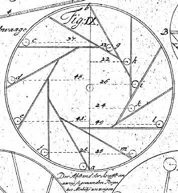
Perhaps because of this, devices resembling the scoop wheel are common in the history of perpetual motion schemes. These are discussed in Ord-Hume. A general flavor of tympanum-like perpetual motion schemes may be obtained from the following illustration, Fig. IX of Tab[leau] VII in Tomus [Volume] I of Leupold's Theatrum Machinarum:
A Tympanum-like Perpetual Motion Scheme
(Leupold. Theatrum Machinarum.
1724. Tomus I, Tab[leau] VII, Fig IX.)
Image public domain
Devices of this sort are also linked to medieval Arabic water (mercury) clocks and to descending cylinder compartmented water clocks.
Several variations on the tympanum and scoop wheel are discussed in Thomas Ewbank's Hydraulics. These discussions are reproduced here from the 16th edition of 1876. Ewbank's treatment is concerned entirely with the hydraulic aspects of these devices.
[Page 110; running head "The Tympanum."; text public domain]
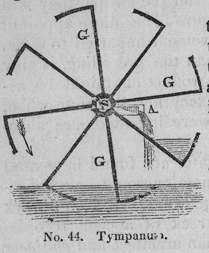
The tympanum consists of a series of gutters united at their open ends to a horizontal shaft, which is made hollow at one end and placed a little higher than where the water is to be elevated; the gutters are arranged as radii, and are of sufficient length to extend from the shaft to a short distance below the surface of the water, as represented by the annexed diagram.
|
|
S, the shaft; G, G, the gutters; A, a trough to take away the water. The arrow indicates the direction in which the wheel turns; each gutter, as it revolves scoops up a portion of water and elevates it, till by the inclination to the axle, it flows towards the latter, and is discharged through one end of it. |
Were the machine made as thus represented, i.e. of separate gutters and not connected to each other, it could not be durable, as the weight of water raised at the end of each would have a tendency to break them at their junctions with the shaft. The ancients therefore made two strong disks of plank well jointed together, of the diameter of the intended wheel, these they secured on a shaft, at a distance from each other, proportionate to the quantity of water required to be raised. Any number of plank partitions (Vitruvius says eight) were then inserted in the direction of radii between these disks, and were well secured to them, and made tight by caulking and pitch. The spaces between them, at the circumference of the wheel, were also closed, with the exception of an opening left for the admission of water to each; and where each partition joined the shaft, a hollow channel was formed in the later, parallel to the axis, through which the water was discharged into a trough or gutter placed immediately under it. The tympanum is obviously a modification of the jantu of India, or rather it is a number of them combined, and having a revolving instead of a vibratory movement. [See the section from Ewbank on The Jantu below.] It is the first machine described by Vitruvius; of which he observes, "it does not raise the water high, but it discharges a great quantity in a short time." B. x Cap. 9. From its resemblance to a drum or tabor, it was named by the Romans Tympanum.
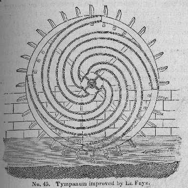
The prominent defect of the tympanum arises from the water being always at the extremity of a radius of the wheel, by which its resistance increases as it ascends to a level with the axis; being raised at the end of levers which virtually lengthen till the water is discharged from them[.] There is no reason to suppose that this defect, if perceived at all by ancient mechanicians, was ever remedied by the; to most persons, the idea would never occur, that so simple a machine could be essentially improv- [page 111 begins] ed, and its having been described as represented in the last figure by a Roman philosopher and engineer; it was most likely used as thus constructed, through the remote ages of antiquity, to the early part of the last century, when a member of the Royal Academy of Sciences, of France, M. De La Faye, developed by geometrical reasoning, a beautiful and truly philosophical improvement. It is described by Belidor, (Tom. ii, 385, 387,) together with the process of reasoning that led to it[,] "When the circumference of a circle is developed; a curve is described, (the involute) of which all the radii are so many tangents to the circle; and are likewise all respectively perpendicular to the several points of the curve described, which has for its greatest radius, a line equal to the periphery of the circle evolved. Hence, having an axle whose circumberence a little exceeds the height which the water is proposed to be elevated, let the circumference of the axle be evolved, and make a curved canal, whose curvature shall coincide throughout exactly with that of the involute just formed; if the furtehr extremity of this canal be made to enter the water that is to be elevated, and the other extremity abut upon the shaft which is turned; then in the course of rotation, the water will rise in a VERTICAL DIRECTION, tangential to the shaft, and perpendicular to the canal, in whatever position it may be." See No. 45.
Thomas Ewbank. Hydraulics. 16th ed., 1876. Fig. 45.
Image public domain
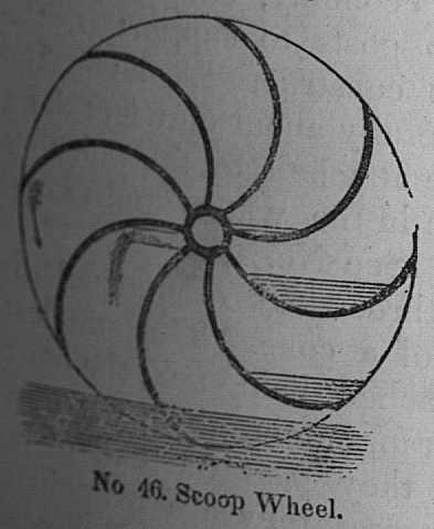
The above figure from Belidor, is composed of four tubes only, but it is frequently constructed with double the number. Instead of tubes, curved partitions between closed sides of the wheel are oftener used, as in the SCOOP WHEEL --- which consists of a number of semicircular partitions, extending from the axle to the circumference of a large flat cylinder. As it revolves int he direction of the arrows, the extremities of the partitions dip into the wter, and scoop it up, and as they ascend, discharge it into a trough placed under one end of the shaft, which is hollowed into as many compartments as there are partitions or scoops. Wheels of this description, and propelled by steam, are extensively used to drain the fens of Lincolnshire[.]
Thomas Ewbank.
Hydraulics. 16th ed., 1876. Fig. 46.
Image public domain
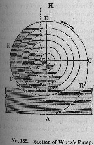
On page 363-364, Ewbank describes and illustrates a spiral pump attributed to H. A. Wirtz, of Zurich, in 1746. This material is of interest to the rolling ball constructor primarily because of the illustrations, for while the form of Wirtz' pump might be adapted to rolling ball practice (and indeed it is essentially a single-guttered tympanum using an Archimedean spiral), the principle of operation of Wirtz pump depends upon properties of fluids, air and water, not present in rolling balls. Still, the passage is interesting and so it is reproduced below. The reference to Heron is to Hero of Alexandria, who devised a fountain which operated by means of water compressing air, which in turn propels a fountain of water.
Thomas Ewbank.
Hydraulics. 16th ed., 1876. Fig. 165.
Image public domain
Thomas Ewbank.
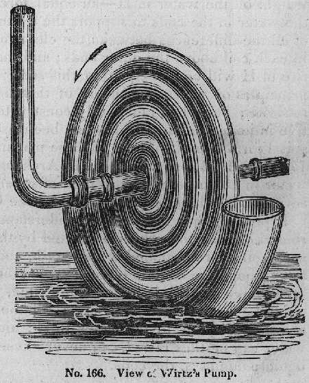
Hydraulics. 16th ed., 1876. Fig. 166.
Image public domain
[Ewbank, Page 363; text public domain] By far the most novel and interesting modification of Heron's fountain was devised in the year 1746 by H. A. Wirtz, a Swiss pewterer or tinplate worker of Zurich. It is sometimes named a spiral pump, and was made to raise water for a dye house in the vicinity of that city. What the circumstances were that led Wirtz to its invention we are not informed --- whether it was suggested by some incident, or ws the result of reasoning alone. It is represented in the illustrations Nos. 165 and 166, the first being a section and the latter an external view.
Wirtz's machine consists either of a helical or a spiral pipe. As the former it is coiled round in one plane as A B C D E F in No. 165. As a spiral it is arranged round the circumference of a cone or cylinder, and then resembles the worm of a still. [Note - I think Ewbank has it backwards here; a spiral is a two dimensional form, and a helix is a three dimensional form. - DMM] The interior end at G is united by a water tight joint to the ascending pipe H. See No. 166. The open end of the coil is enlarged so as to form a scoop. When the machine, immersed in water as represented, is turned in the direction of the arrow[,] the water in the scoop, as the latter emerges, passes along the pipe driving the air before it into G H, where it escapes. At the next revolution both air and water enter the scoop; the water is driven along the tube as before, but is separated from the first portion by a column of air of nearly equal length. By continuing the motion of the machine another portion of water and another of air will be introduced. The body of water in each coil will have both its ends horizontal, and the included air will be of about its natural density; but as the diameters of the coils diminish towards the centre, the column of water which occupied a semicircle in the outer coil, will occupy more and more of the inner ones as they approach the centre G, till there will be a certain coil, of which it will occupy a complete turn. Hence it will occupy more than the entire space within this coil, and consequently the water will run back over the top of the succeeding coil, into the right hand side of the next one and push the water within it backwards and raise the other end. As soon as the water rises in the pipe G H, the escape of air is prevented when the scoop takes in its next quantity of water. Here, then, are two columns of water acting against each other by hydrostatic pressure, and the intervening column of air. They must compresss the air between them, and the water and air columns will now be unequal. This will have the general tendency to keep the whole water back and cause it to be higher on the left or rising side of each coil, than on the other. The excess of height will be just such as produces the compression of air between that and the preceding column of water. This will go on increasing as the water mounts in H. Now at whatever height the water in H may be, it is evident that the air in the small column next to it will always be compressed with the weight of the water in H --- an equal force must therefore be exerted by the water in the coils to support the column in H. This force is the sum of all the differences between the elevation of the inner ends of the water in each coil above the outer ends; and the height to which the water will rise in H will be just equal to this sum. Dr. Gregory observes that the principles on which the theory of this machine depends are confessedly intricate; but when judiciously constructed, it is very powerful and effective in its operation. It has not been ascertained whether the helical or spiral form is best. Some of these machines were erected in Florence in 1778. In 1784, one was made at Archangelsky, that raised a hogshead of water in a minute to an elevation of seventy-four feet, and thorugh a pipe seven hundred and sixty feet long. See Gregory's Mechanics, vol. ii.
It perhaps may facilitate an understanding of this curious machine, by remarking that the pressure exerted by the column of water in one isde of each coil is proportioned to its length, and that this pressure is transmitted, through the column of air between them, to that of the next: the combined force of both is then made to act, by the revolution of the tubes[,] upon the third column, and so on till the accumulated force of them all is communicated to the water in H; and hence the elevation to which water can thus be raised, can never exceed the sum of the altitudes of the liquid columns in the coils.
Jacob Leupold.
Theatrum Machinarum.
(Tom. III: Theatrum Machinarum Hydraulicarum, Tom. I.)
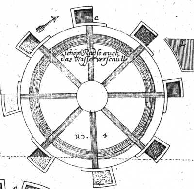
Tab. XI, Fig. 4.
Image public domain.
The device illustrated below seems to be a scoop wheel powered by the flowing stream from which it scoops water. Such devices were common in the near east and Islamic countries (see, for example, Donald R. Hill. A History of Engineering in Classical and Medieval Times), where were termed "norias." It is not clear to me that the scoops as shown would work.
Jacob Leupold.
Theatrum Machinarum.
(Tom. III: Theatrum Machinarum Hydraulicarum, Tom. I.)
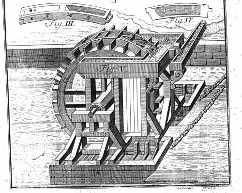
Tab. XIII, Fig. 5.
Image public domain.
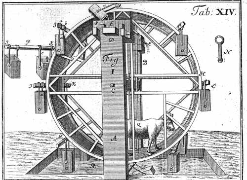
Jacob Leupold.
Theatrum Machinarum.
(Tom. III: Theatrum Machinarum Hydraulicarum, Tom. I.)
Tab. XIV, Fig. 1.
Image public domain.
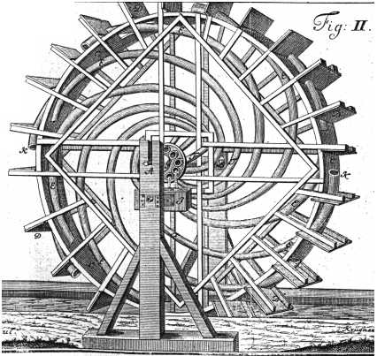
Jacob Leupold.
Theatrum Machinarum.
(Tom. III: Theatrum Machinarum Hydraulicarum, Tom. I.)
Tab. XIV, Fig. 2.
Image public domain.
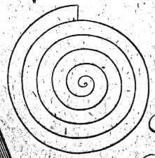
In early 1997, before I was aware of Ewbank's treatment of the scoop wheel but after I had read about spiral rolling ball devices in Ord-Hume, I constructed what I then called an "Archimedean Spiral" to lift balls. As constructed, this was a test device operated by hand rather than a practical part of a rolling ball sculpture.
Lacking De La Faye's mathematical expertise, I used single "Archimedean" spiral curve. An Archimedean spiral does have the interesting property that when rotated with uniform angular velocity the linear velocity of the spiral past, say, the y axis is constant. Visually, this results in a very stable, constant-velocity ascent for balls in the spiral.
An Archimedean Spiral
(Leupold.
Theatrum Machinarum. 1724.
Tomus I, Tab[leau] LI, Unnumbered Figure)
Image public domain
To draw this curve, I used the Gnuplot mathematical plotting utility available from the Free Software Foundation. Using Gnuplot, I plotted and printed the polar coordinate system equation for an Archimedean spiral: r = a theta, where r is the radius which plots out the points of the spiral, a is an arbitrary constant, and theta is an angle whose value we continuously increase from 0 to an arbitrarily large value (often greater than 360 degrees). I used SpraymountTM (brand, TM of 3M) artist's adhesive to glue this printout to a piece of ordinary 1" thick pine (really 3/4" thick given US nominal dimensioning practices for wood). Using a scroll saw, I cut along this spiral, and then cut parallel to this spiral to relieve a space for the ball to roll in.
I then realized that I had made no allowance for anyplace to put an axle, so I took a dowel about 6 inches long, recessed a hole in it so that the pointy central tip of my wooden spiral would be on-center, and relied on the strenght of wood glue. To use this device, I took another piece of wood, drilled a hole in it for the axle, and mounted it at about 10 degrees off of vertical. I put the axle of my spiral through this hole and rested the spiral against this backing piece. In this way, the balls in the spiral rested against this backing piece of wood as they ascended. In retrospect, I would have been better off mounting my spiral between two transparent disks of acrylic sheet.
Near the center of this device, I drilled a hole in the backing plate through which the ball could escape. I discovered that given the general crudeness of my construction, it was easy for the ball to overshoot this hole and to become lodged in the very center of the spiral. I would suggest, instead, a design where the ball can follow the spiral all the way to a hollow axle and be discharged through the axle.
Even with this hacked-together prototype, the beauty of the motion of balls through a spiral scoop wheel was evident.
With the exception of material noted as being in the public domain, the text, images, and encoding of this document are copyright © 1997 by their author(s) and editor(s): David M. MacMillan.
This document is licensed for private, noncommercial, nonprofit viewing by individuals on the World Wide Web. Any other use or copying, including but not limited to republication in printed or electronic media, modification or the creation of derivative works, and any use for profit, is prohibited.
This writing is distributed in the hope that it will be useful, but "as-is," without any warranty of any kind, expressed or implied; without even the implied warranty of merchantability or fitness for a particular purpose.
In no event will the author(s) or editor(s) of this document be liable to you or to any other party for damages, including any general, special, incidental or consequential damages arising out of your use of or inability to use this document or the information contained in it, even if you have been advised of the possibility of such damages.
In no event will the author(s) or editor(s) of this document be liable to you or to any other party for any injury, death, disfigurement, or other personal damage arising out of your use of or inability to use this document or the information contained in it, even if you have been advised of the possibility of such injury, death, disfigurement, or other personal damage.
All trademarks or registered trademarks used in this document are the properties of their respective owners and (with the possible exception of any marks owned by the author(s) or editor(s) of this document) are used here for purposes of identification only. A trademark catalog page lists the marks known to be used on these web pages. Please e-mail dmm@lemur.com if you believe that the recognition of a trademark has been overlooked.
Version
1.2, 1998/06/20.
Feedback to dmm@lemur.com
http://www.database.com/~lemur/rbt-scoopwheel.html
Go to the: