Rolling Ball Technology
An Online Technical Reference Devoted to
Rolling Ball Sculptures, Clocks, and other Devices
By Members of the rolling-ball@lemur.com List
Lifters: Unequal Buckets
By David M. MacMillan
Because rolling balls partake of some, but not all, of the
characteristics of a fluid, some devices originally
designed for use with fluids such as water may be used with
rolling balls instead.
The following device appears in
Thomas Ewbank's Hydraulics,
and is reproduced here from the 16th edition of 1876.
Following this passage from Ewbank is a short passage
by the present author
on the application of this device to rolling balls.
The italicization and punctuation of Ewbank have been
retained here, and the original pagination has been indicated,
but the typeset line breaks have not.
The text and illustrations from Ewbank are in the public domain.
Editorial additions by the present author are indicated by
[square brackets] and are covered by the copyright of the
present document.
The modern reader may find Ewbank's style elliptical, and that
my notes compound this problem, but I find in this style
much of the charm of older texts.
[Page 64; running head "Self-Acting Buckets";
text public domain]
SELF-ACTING, OR GAINING AND LOSING BUCKETS
In the latter part of the 16th, or the beginning of the 17th
century,
a machine for raising water, was in use in Italy,
which is entitled to particular notice,
on account of its being alleged to be the first one of the kind
which was self-acting;
and in that respect, was the forerunner of the motive
'Fire Engine' itself [i.e., a steam engine with automatically
operated valve gear].
It appears to have been first described by
Schottus
[Gaspar
Schott, 1608-1666] in his Technica Curiosa [(1664)].
According to Moxon,
his description was taken from one in actual operation at
"a nobleman's house at Basil,"
(Mech. Pow. 107.)
But Belidor [possibly Bernard Forest de Belidor,
Architecture Hydraulique. Paris. 1737-1739],
says the first one who put such a thing in execution,
was Gironimo Finugio, at Rome in 1616;
although Schottus has long before
contrived an engine for this purpose
[n.b., Schott would have been 8 years old in 1616].
Moxon has given a figure and description of one,
but without naming the source from whence he obtained it:
he says it was "made at Rome, in the convent of St. Maria de
Victoria: the lesser bucket did contain more than a whole urn of water,
(at Rome they say un barile,) but before,
while they used lesser buckets,
the engine wanted success."
It would seem that it was to one of these
'Roman Engines,' that the Marquis of Worcester referred,
in the 21st proposition of his
Century of Inventions:
"How to raise water constantly with two buckets only,
day and night,
without any other force than its own motion,
using not so much as any force, wheel or sucker,
nor more pulleys than one,
on which the cord or chain rolleth,
with a bucket fastened at each end.
This I confess I have seen and learned of the great mathematician
Claudius [Clavius [Klau], Christoph [Christopher] (1538-1612);
see the History
of Astronomy page],
his studies at Rome,
he having made a present thereof unto a cardinal,
and I desire not to own any other men's inventions,
but if I set down any, to nominate likewise the inventor."
[See Note on the Marquis of Worcester]
[Image public domain]
|
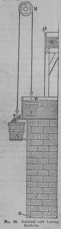
The machine described by Moxon,
is encumbered with too many appendages for popular illustration ---
its essential parts will be understood by the accompanying diagram,
from Hachette's Traité Elémentaire des Machines,
Paris, 1819.
Over a pulley S,
are suspended two vessels A and B,
of unequal dimensions.
The smaller one B, is made heaver than A when both are
ampty, but lighter when they are filled.
It is required to raise by them part of the water from the spring
or reservoir E,
into the cistern Z.
As the smaller bucket B, by its superior gravity,
descends into E,
(a flap or valve in its bottom admitting the water,)
it consequently raises A into the position
represented in the figure.
A pipe F, then conveys water from the reservoir into A,
the orifice or bore of which pipe,
is so proportioned, that both vessels are
filled simultaneously.
The larger bucket then preponderates,
descending to O, and B at the same time rising
to the upper edge of Z,
when the projecting pins O O, catch against others on the
lower side of the buckets, and overturn them at
the same moment.
The bails or handles are attached by swivels to the side,
a little above the [Page 65 begins] centre of gravity.
As soon as both vessels are emptied, B again preponderates,
and the operation is repeated without any
attendance,
as long as there is water in E and the apparatus continues
in order.
[Note: Depending upon your WWW browser, the images
in this document may
look better if saved to separate files and viewed with a separate
image-viewing program.]
|
In Moxon's machine, the vessels were filled by two separate
tubes of unequal bore;
the orifices being covered by valves,
to prevent the escape of water while the buckets were in motion;
these valves were opened and closed by means of cords attached
to the buckets.
The efflux through F in the figure,
may easily be stopped as soon as A begins to descend,
by the action of either bucket on the end of a lever attached
to a valve, or by other obvious contrivances.
The water discharged from A,
runs to waste through some channel provided for the purpose.
These machines are of limited application, since they require
a fall for the descent of A,
equal to the elevation to which the liquid is raised by B.
They may however be modified to suit locations where a less descent
only can be obtained.
Thus, by connecting the rope of B to the periphery of a large
wheel, while that of A is united to a smaller one on the same
axis, water may be raised higher than the larger bucket falls,
but the quanity raised will of course be proportionally diminished.
In Serviere's Collection,
a Gaining and Losing Bucket Machine is described.
Another one was invented in 1725, by George Gerves an
English carpenter, who probably was not aware that he had been
anticipated by continental mechanics upwards of a century before.
He erected one in Buckinghamshire, which was much approved of by
Sir Isaac Newton, Beighton, Desaguliers, Switzer, and others.
Mr. Beighton,
who drew up a description of it, observes that it was so free
from friction, that "it is likely to continue an age without
repair;["] and Dr. Desaguliers on inserting an
account o fit in his Experimental Philosophy, vol. ii, 461,
says, "this engine has not been our of order since it was first
set up, about fifteen years ago."
Notwithstanding these favourable testimonials, it has fallen
into disuse.
It was much too complex and combersome, and of too limited application
ever to become popular.
The principle of self-action in all these machines is no modern
discovery, for it was described by Heron [Hero] of Alexandria,
who applied it to the opening and closing of doors of a temple,
and to other purposes.
The motive bucket when filled, descended and communicated by
a secrete cord the movement required,
and when its contents were discharged (by a siphon similar
to the one figured in the Clepsydra of Ctesibius,
in our fifth book,) it was again raised by a weight at the other
end of the cord,
like the bucket, in the last figure.
See De Naturæ Simia sen technica macrocosmi historia,
by Robert Fludd, (the English Rosicrucian.)
Oppenheim, 1618, pp. 478 and 489, where several similar
contrivances are figured -- hence the device is much older than has been
supposed.
Perhaps the best modification of the 'Gaining and Losing Bucket',
is Francini's, a description of which may be seen in
our account of the Endless Chain of Pots.
[See Note on the Francini's Endless Chain of Pots]
[Image public domain]
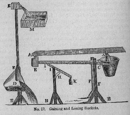
A lever machine described by Dr. Desaguliers
[Dr. John Theophilus Desaguliers (1683-1744), a prominent
18th century English scientific
writer and educator] may here be noticed.
"A A, (No. 17,) are two spouts running from a gutter or
spring of water, into the two buckets D and E.
D containing about thirty gallons and being called the
losing bucket, and E the gaining bucket,
containing less than a quarter part of D,
as for example six gallons.
D E, is a lever or beam movable about the axis or centre C,
which is supported by the pieces F F,
between which the bucket D can descend when
the contrary bucket E is raised up, D C,
is to C E, as one is to four.
G L is an upright piece,
through the top of which the lever K I moves about the cetnere L,
sometimes resting on the prop H,
and sometimes raised from it by the
[page 66 begins]
pressure of the arm C E on the end I.
The bucket D when empty,
has its mouth upwards, being suspended as above mentioned.
The end D with its bucket is also lighter than the end with bucket E, when both
are empty.
By reason of the different bore of the spouts, D is filled almost
as soon as E, and immediately preponderating,
sinks down to D,
and thereby raises the contrary end of the lever,
and its bucket up to the cistern M,
into which it discharges its water;
but immediately the bucket D becoming full,
pours out its water, and the end of the lever
E comes down again into its horizontal situation,
and striking upon the end I of the loaded lever I K,
raises the weight K,
by which means the force of its blow is broken.
If the distance A B or the fall of the water be
about six feet,
this machine will raise the water into the cistern M twenty four
feet high.
Such a machine is very simple and may be made in any proportion
according to the fall of the water,
the quanity allowed to be wasted,
and the height to which the water must be raised."
"Some years ago," Dr. Desaguliers continues,
"a gentleman showed me a model of such an engine varying
somewhat from this, but so contrived as to stop the running
of the water at A A, when the lever D E began to move.
He told me he had set up an engine in Ireland
which raised about half a hogshead of water a minute,
forty feet high,
and did not cost forty shillings a year to keep it in repair,
and that it was not very expensive to set up at first."
Experimental Philosophy, vol. i, 78.
Application of the Unequal Buckets to Rolling Balls
The primary difference between fluids and balls insofar
as this device is concerned is that fluids in practice
are available in continuously varying quantities while
balls are available only in discrete quantities.
Moreover, in any given device,
balls are typically available in a very few
different weights --- most often a single weight.
Other differences between fluids and balls, such as the ability
of fluids to react to pressure changes, are not significant here.
Consider two buckets, A and B, connected as in
Ewbank's Gaining and Losing Buckets.
Assume that these buckets are so designed that they may
receive and discharge one or more balls as appropriate.
In practice, it may be necessary to provide further guides
for the motion of these buckets.
Let A represent the descending bucket (and when appropriate,
its empty weight) and B represent the ascending bucket.
In the simplest case (see the discussion of relative bucket
capacities below),
B must be of sufficient size to accomodate a single ball,
and A must be
of sufficient size either for two balls or a single larger ball.
The empty weight of B must be slightly more than the empty weight of A,
so that when
the system is at rest B descends to a ledge or other stop
placed at the midpoint. At rest, A should be at the same level as,
or perhaps slightly below, B.
In the most basic form of operation,
the first ball to approach this device must be guided into B,
the ascending bucket.
The device remains stationary at this point.
The second ball must be guided into A, the descending bucket.
Since the weight of B exceeds A, and both balls are presumed
to be of the same weight, B with a ball outweighs A with a ball,
and the device remains stationary.
However, when a third ball enters the device and is guided to A,
A then outweighs B. A descends, B rises.
When B reaches its maximum height,
some mechanism releases the ball
from it just before another mechanism
releases the two balls from A.
B then descends, A rises, and
the device then returns to rest.
A similar device might be built which used two streams
of balls of different weights.
A ball from the lighter stream might be directed into B,
and, if the ball weights were correctly proportioned,
a single ball from the heaver stream might suffice to
operate the lifter.
Similarly, multiple balls from a lighter stream might
be directed to A, to lift a single ball from the heavier stream.
In general, to use this device to raise balls,
if ascending bucket B is designed to hold b balls,
and descending bucket A is designed to hold a balls,
the total weight of bucket B plus its b balls must
exceed the total weight of A plus (a - 1) balls,
but be less
than the total weight of A plus a balls.
In this manner, the device is triggered when the
ath ball
enters A.
It should be remembered that while the purpose of Ewbank's
Gaining and Losing Buckets is to raise water continually,
this is not necessarily the purpose of this device when employed
in rolling ball sculpture.
The sculptor's intent may well be a pleasing inefficiency,
a randomness of motion, or a complex periodicity.
There are several ways in which the balls may be supplied
to this device.
The easiest way is to supply them from two independent tracks;
thus, one source of balls goes into A, and another into B.
This raises the possiblity that the device might be triggered
while ascending bucket B is empty.
Such an action may be desirable or undesirable, depending
upon the sculpture.
The alternative to separate supplies is to supply the
balls from a single source, using a switching mechanism
(which might be a passive switch).
In a passive switch, the first ball would roll into B;
subsequent balls would attempt to roll into B, but would
encounter the first ball and roll away into A.
Alternatively, an active switch at B could be designed to
close the path into B once the first ball has arrived there.
Subsequent balls would be diverted by this switch into A.
This switch would be reset by B when it returned to its
resting position.
Switching allows the sculptor to ensure that ascending bucket B
does contain a ball when the device goes into operation.
There is also considerable freedom of design concerning the
fate of supplied balls while the device is in operation:
they may be queued for future use,
diverted elsewhere,
or fall through (which is really just another form of diversion).
The applications of rolling balls to the lever
variant proceeds along similar lines.
Francini's "Chain of Pots" (see below)
might also be adapted to rolling balls.
I have not yet built a rolling ball device to these
speculative plans.
However, I believe that the idea of adapting the
hydraulic Gaining and Losing Buckets to rolling ball apparatus
is an original idea.
It was conceived on 19 X 97.
I have not, however, conducted an exhaustive search
of previous rolling ball mechanisms;
it may well be that this idea has been employed before.
A Century of Inventions
refers to
A Century of the Names and Scantlings of Such Inventions
As at Present I can Call to Mind to have Tried and Perfected,
which (my former Notes being lost) I have,
at the instance of a powerful Friend, endeavoured now in
the Year 1655, to set these down in such a way as may
sufficiently instruct me to put any of them in practice, by
Edward Somerset, Second Marquis of Worcester.
This was
published in 1663, but written in 1655 during his imprisonment
in the Tower of London during the English Civil War;
it has been reprinted a number of times.
The reprint contained in
Henry Dircks'
The Life, Times and Scientific Labors of
the Second Marquis of Worcester,
to which is added, a reprint of his Century of Inventions, 1663.
London, 1865.
is at the time of writing available online as a part of
The Steam
Engine Library.
Invention No. 21 of Dircks' text, as presented in the Steam Engine Library,
reads as follows.
In the transcription below,
short 's' characters substituted for incorrect scannings
of the long 's' as 'f,' and the matter enclosed within
[square brackets] is literally present in the Steam Engine Library
text.
"MS" refers to the Harleian manuscript No. 2428 in the British Musuem;
"P" refers to the Partington edition of 1825.
Dircks' text and illustrations are in the public domain.
21. How to raise water constantly with two Buckets
onely day and night, without any other force then its own motion,
using not so much as any force, wheel, or sucker,
nor more pullies then one, on which
the cord or chain rolleth with a
[Bucket fastened at each end.]
This, I confess,[confess to have seen]
I have seen and learned
[in the great Mathematician's study, Clauius at Rome] of the great
Mathematician Claudius [Claudius]
[Clavius's Studies at Rome] his studies at Rome, he having
made a Present thereof unto a Cardinal;
and I desire not to own any other mens [man's. MS. and P.]
inventions, but if I set down any, to nominate likewise the inventor.
Dircks' version contains considerable commentary, as well as illustrations
not present in the original.
Curiously, Dircks seems unaware of the "unequal bucket"
interpretation of Somerset's 21st Invention.
Dircks gives instead a curious combination of a chain of
buckets and a waterwheel.
He says:
We have next to
consider the present article No. 21. The conditions stated require the use of
but
one pulley, one cord, and two buckets, without any "force" or pump
plunger, or " any wheel, or sucker." An arrangement so simple seems
only possible to be attained by some such plan as that exhibited in the
illustration given below. We have here an endless chain or cord,
a b, passing over the pulley C, with a bucket D, at
the upper end; and another bucket E, at the lower end; the first in the act of
discharging its contents into the trough G, the second re-charging with water
at
the level E. This endless chain is further supplied with a series of conical
or
other shaped buckets, a, á, set on the endless cord in a reverse
direction,
so as to receive water conveyed from an upper stream by the spout F, by which
means the side B, of the cord will descend, and the side A, ascend,
"without
ny other force than its own motion," and that "with two buckets
only,
day and night." On the side a' the conical buckets reverse and empty
themselves, thereby lightening the ascending side A, of the endless chain or
cord.
Image public domain
Given Ewbank's solution, it seems as if Dircks' interpretation
is unlikely to be correct.
In the 1887 edition edited by John Phin, the 21st Invention
is given thus:
21. How to raise water constantly with two Buckets onely
day and night, without any other force then its own motion,
using not so much as any force, wheel or sucker,
nor more pulleys than one on which the cord or chain
rolleth, with a bucket fastened at each end.
This I confess1 I have
seen and learned2 of the
great Mathematician Claudius3
his studies at Rome, he having made a Present
thereof unto a Cardinal;
and I desire not to own any other mens4
inventions, but if I set down any,
to nominate likewise the inventor.
Phin notes that the Harleian MS differs at the points indicated:
1confess to have.
2in the great Mathematician's study,
Clauius at Rome.
3Clauius.
4man's.
Phin gives no further commentary on, nor any illustration
of, Somerset's Invention.
Phin, John, Ed.
An Exact Reprint of the Famous
Century of Inventions. Of The Marquis of Worcester
(First Published in 1663) with
Introduction, Notes and a Life of the Author.
NY: The Industrial Publication Company, 1887.
This edition is in the public domain.
Ewbank describes and illustrates several schemes for
lifting water using chains of buckets or pots.
These chains of pots are essentially similar to the
"cradles" on chains used by many rolling ball sculptures.
These chains differ from each other primarily in the method by
which they are powered.
The device of Francini, referenced above, is powered by
the flow of water over a secondary bucket chain.
It is not dissimilar from the single-chain device
proposed by Dircks.
Ewbank describes it as follows,
beginning with an analogy to the well-known "noria,"
or water-lifting wheel powered by a flowing stream
which drives the same wheel:
[Image public domain]
[Page 127; text public domain]
It [the chain of pots] has been adopted as a substitute for water wheels.
As the noria, when its motion is reversed by the admission of
water into its buckets at the upper part of the periphery,
is converted into an overshot wheel --- so the chain of pots,
has in a similar manner, been made to transmit power and
communicate motion with other machines.
In locations where there is a small supply of water,
but which falls from a considerable height,
it becomes a valuable substitute for the overshot wheel,
as a first mover.
It is remarkable that this obvious application of it should not have
occurred to European mechanicians previous to the 17th century.
It was designed by M. Francini, and by the direction of Colbert,
the illustrious and patriotic minister of Louis XIV,
one was erected in 1668, in one of the public gardens of Paris.
A natural spring in this garden supplied water for the
plants.
It was received into a large basin, and to prevent its overflowing,
the surplus or waste water was discharged by a gutter into a well,
at the bottom of which it disappeared into the soil.
M. Francini took advantage of this fall of waste water in the well,
and made it the means of raising a portion of the spring water
sufficiently high to form a jet d'eau[.]
[page 128 begins]
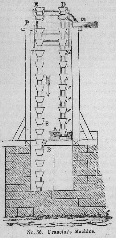
He erected a chain of pots, E, B, No. 56, which reached from
the bottom of the well to such a height above its mouth
as the water to form the jet was required to be raised.
From the upper wheel or drum another chain of pots, D, C, was
suspended and carried round by it,
the lower end dipping into the water to be raised from
spring A.
By this arrangement the weight of the water in descending
the well in the buckets of the first chain,
raised a smaller portion
(allowing for friction) through the same space by the second one --- and a
proportionable quantity still highter.
A spout conveyed this water into the buckets of the driving
or motive chain as shown in B.
These buckets were made of brass,
and wide at the top,
the better to receive water from the spring;
and also that when one was filled, the surplus might fall down its sides
into the next one below, and from that to the third one,
and so on that none might be lost by spilling over.
The buckets of the other chain were of the same form and
material but instead of being open like the former, they were
closed on all sides,
the water being received into them at A,
and discharged from them at m,
through short necks or tubes, e, s,
which are upwards when the buckets ascend,
being connected to the smaller part of the latter.
A pipe from the upper cistern m, conveyed the water
to form the jet.
The arrow indicates the direction in which both chains move.
The vessels on the chains E, B, below B,
descending into the well,
(the bottom of which is not shown,)
[are] full -- while those shown at D, C, are empty.
The chain of Pots has been employed to work pumps in mines,
to propel thrashing machines, &c. &c.a.
[Footnote in the original]
aSee Vol. i of machines approved by
the French Academy[;]
Desaguliers' Philos[.] Vol. ii[;]
Edinburgh Encyc[lopædia]. Vol. x 896.
With the exception of material noted as being in the public domain,
the text, images, and encoding of this document are copyright ©
1997-1998 by
their author(s) and editor(s): David M. MacMillan.
This document is licensed for private, noncommercial, nonprofit
viewing by individuals on the World Wide Web.
Any other use or copying, including but not limited to
republication in printed or electronic media,
modification or the creation of derivative works,
and any use for profit,
is prohibited.
This writing is distributed in the hope that it will be useful,
but "as-is," without any warranty of any kind, expressed or implied;
without even the implied warranty of
merchantability or fitness for a particular purpose.
In no event will the author(s) or editor(s) of this document
be liable to you or to any other party for damages,
including any general, special, incidental or consequential damages
arising out of your use of or inability to use this
document or the information contained in it,
even if you have been advised of the possibility of such damages.
In no event will the author(s) or editor(s) of this document
be liable to you or to any other party for any injury, death,
disfigurement, or other personal damage arising out of your use of
or inability to use this document or the information
contained in it, even if you have been advised of the
possibility of such injury, death, disfigurement, or other
personal damage.
All trademarks or registered trademarks used in this document
are the properties of their respective owners and
(with the possible exception of any marks owned by the
author(s) or editor(s) of this document)
are used here for purposes of identification only.
A trademark catalog page
lists the marks known to be used on these web pages.
Please e-mail
dmm@lemur.com
if you believe that the recognition of a trademark has been overlooked.
Version
1.3, 1998/06/20.
Feedback to dmm@lemur.com
http://www.database.com/~lemur/rbt-ubuckets.html
Go to the: