DMM Varkon® Tutorial
A Beginner's Guide to the Varkon
Parametric Modeling and CAD Application Development System
By David M. MacMillan
Note: The term "method" is perhaps inappropriate here; this is no more than a log of my experiments with projected views.
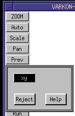
Create a Varkon 2D drawing job. Before proceeding, check to see what view are available by default (press the View button in the standard menu setup, invoking interactive function f195, "Change Active View.")
Now consider a 3D MBS geometry module which draws a box. the code for this module is, initially:
! boxnorotg.MBS
!
! Draw a rectilinear (unrotated) box in the global coordinate system.
!
! Use the same coloring for the lines defining the box as is used for
! demonstration axes in vcl.MBS:
!  X = red, Y = green, Z = blue  (RGB == XYZ)
!

global geometry module boxnorotg(
   float dx;
   float dy;
   float dz;
   float xoffset;
   float yoffset;
   float zoffset
);

   vector lbb;     ! left back bottom; origin
   vector lbt;     ! left back top
   vector lft;     ! left front top
   vector lfb;     ! left front bottom

   vector rbb;     ! right back bottom; origin
   vector rbt;     ! right back top
   vector rft;     ! right front top
   vector rfb;     ! right front bottom

beginmodule

   lbb := vec (0 + xoffset,  0 + yoffset,  0 +zoffset);
   lbt := vec (0 + xoffset, dy + yoffset,  0 +zoffset);
   lft := vec (0 + xoffset, dy + yoffset, dz +zoffset);
   lfb := vec (0 + xoffset,  0 + yoffset, dz +zoffset);

   rbb := vec (dx + xoffset,  0 + yoffset,  0 +zoffset);
   rbt := vec (dx + xoffset, dy + yoffset,  0 +zoffset);
   rft := vec (dx + xoffset, dy + yoffset, dz +zoffset);
   rfb := vec (dx + xoffset,  0 + yoffset, dz +zoffset);

   lin_free (#1, lfb, lbb: PEN=4);
   lin_free (#2, lft, lbt: PEN=4);
   lin_free (#3, lfb, lft: PEN=3);
   lin_free (#4, lbb, lbt: PEN=3);

   lin_free (#5, rfb, rbb: PEN=4);
   lin_free (#6, rft, rbt: PEN=4);
   lin_free (#7, rfb, rft: PEN=3);
   lin_free (#8, rbb, rbt: PEN=3);

   lin_free (#9,  lbb, rbb: PEN=2);
   lin_free (#10, lfb, rfb: PEN=2);

   lin_free (#11, lbt, rbt: PEN=2);
   lin_free (#12, lft, rft: PEN=2);

   b_plane (#13, lbt, lft, rft, rbt: LEVEL=1);
   b_plane (#14, rbt, rft, rfb, rbb: BLANK=0);
   b_plane (#15, lft, lfb, rfb, rft: BLANK=0);

endmodule
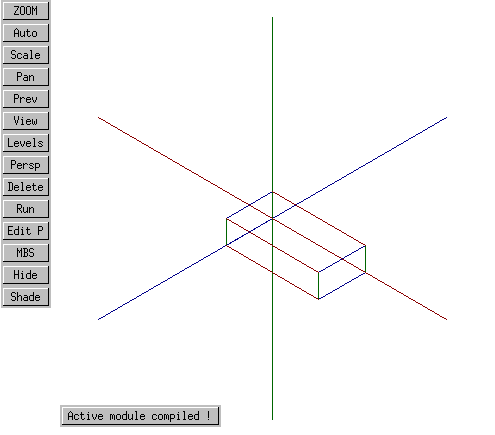
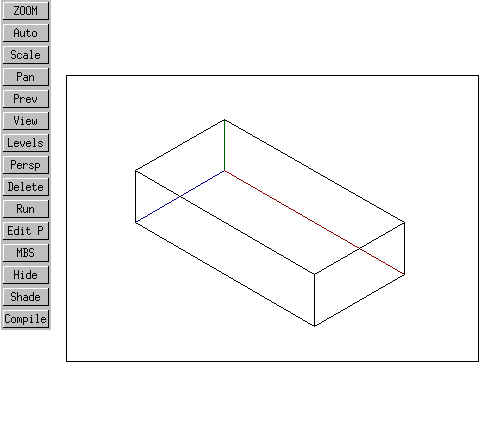
Viewed in a 3D geometry job, with some coordinate axes drawn in for clarity (vcl.MBS), this box looks like this.
GLOBAL GEOMETRY MODULE test3d();

VECTOR neworigin1;

BEGINMODULE

  part(#1,vclb(15, 0, 0));
  neworigin1:=vec(0, 0, 0);
  csys_1p(#3,"lcs1", neworigin1, 0, 0, 0);
  part(#4,boxnorot(8, 2, 4, 0, 0, 0),#3);

ENDMODULE
Now, let's modify this module so that it understands something about views - in particular, so that it understands the concept of an isometric view. This involves the use of the cre_view () MBS procedure. Since this procedure, when used to create an isometric view, requires parameters in 3D, we cannot use it directly from within our 2D drawing job. However, we can use it from within the 3D geometry module.
To give the boxnorotg.MBS module the ability to display the box in four views (front, top, right side, isometric), we first modify it to accept a parameter which encodes the desired view:
global geometry module boxnorotg(
   float dx;
   float dy;
   float dz;
   float xoffset;
   float yoffset;
   float zoffset;
   int    view
);
Then we add the following code to the beginning of the module:
beginmodule

if view = 0 then
   cre_view ("front", vec(0,0,1));  ! front,      or X,Y view
   act_view ("front");
elif view = 1 then
   cre_view ("top", vec(0,1,0));    ! top,        or X,Z view
   act_view ("top");
elif view = 1 then
   cre_view ("top", vec(1,0,0));    ! right side, or Y,Z view
   act_view ("top");
else
   cre_view ("iso", vec(1,1,1));    ! isometric view in 1st quadrant
   act_view ("iso");
endif;
Let's now call this 3D box module from the active module of our 2D drawing job, specifying an isometric view (view number 3 in our system of views):
GLOBAL DRAWING MODULE testdraw();

BEGINMODULE

  part(#1,vclb(15, 0, 0));
  part(#2,boxnorotg(1, 3, 5, 0, 0, 0, 3));

ENDMODULE
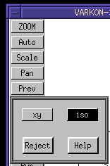
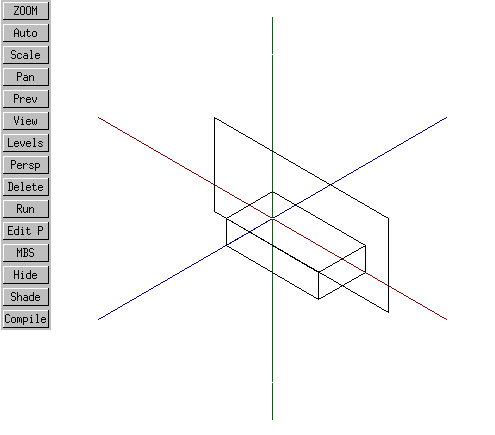
The box looks pretty much as it did in the 3D job, except of course that it's been projected into a 2D job. Note, however, that something curious has happened with the views defined to this 2D job - they now include not only an XY view, but an ISO view:
It is even possible now, within this 2D drawing job, to switch between 2D and 3D views of the model without respecifying the view to boxnorotg.MBS.
Let's assume we want to construct a 2D engineering drawing in which this isometric view is projected. The first step in constructing such a drawing would be to draw a big rectangle indicating the border of the drawing. Drawing occurs only in the XY plane, and the box is only 2 x 4 x 8, so if we make our lower left-hand corner, say, (-5, -2) and our upper right-hand corner (10, 5) we ought to catch everything in the drawing. To do this, modify the active (2D drawing) module in this way:
GLOBAL DRAWING MODULE testdraw();

FLOAT xmin;
FLOAT ymin;
FLOAT xmax;
FLOAT ymax;

BEGINMODULE

  part(#1,vclb(15, 0, 0));
  part(#2,boxnorotg(8, 2, 4, 0, 0, 0, 3));
  xmin:=-5;
  ymin:=-2;
  xmax:=10;
  ymax:=5;
  lin_free(#3,vec(xmin, ymin), vec(xmax, ymin));
  lin_free(#4,vec(xmax, ymin), vec(xmax, ymax));
  lin_free(#5,vec(xmax, ymax), vec(xmin, ymax));
  lin_free(#6,vec(xmin, ymax), vec(xmin, ymin));

ENDMODULE
Unfortunately, this does not produce the intended results. Instead of being drawn in the plane of the screen, the border box has been drawn in the XY coordinate system of the model and then projected, along with the model, onto the screen.
As an experiment, let's now project not one but two 3D box models, each using a different type of view. The first one we'll project is simply the isometric view of the box as before. In addition, we'll project a front view of another box at some distance from the first:
GLOBAL DRAWING MODULE testdraw();

FLOAT xmin;
FLOAT ymin;
FLOAT xmax;
FLOAT ymax;

BEGINMODULE

  part(#1,vclb(15, 0, 0));
  part(#2,boxnorotg(8, 2, 4, 0, 0, 0, 3));
  part(#3,boxnorotg(8, 2, 4, 10, 0, 0, 0));
  xmin:=-5;
  ymin:=-2;
  xmax:=10;
  ymax:=5;
  lin_free(#4,vec(xmin, ymin), vec(xmax, ymin));
  lin_free(#5,vec(xmax, ymin), vec(xmax, ymax));
  lin_free(#6,vec(xmax, ymax), vec(xmin, ymax));
  lin_free(#7,vec(xmin, ymax), vec(xmin, ymin));

ENDMODULE
As will be seen, something interesting has occurred. The first, isometric box has been projected isometrically. The second box has been projected frontally. The drawing of the border occurs in the coordinate system of the second, frontal box.
The coordinate system of this second, frontal box is of course the XY coordinate system - the very system we require for our drawing. It therefore appears that in order to do our drawing, two options are present:
Such a 3D view creation module might look like this:
! frontview.MBS

! Create a "front (X,Y; Z=0) view in 3-d

! This module is placed in the public domain by its author,
! David M. MacMillan

global geometry module frontview (
);

beginmodule

cre_view ("front", vec(0,0,1));  ! front, or X,Y view
act_view ("front");

endmodule
Invoking it thus:
GLOBAL DRAWING MODULE testdraw();

FLOAT xmin;
FLOAT ymin;
FLOAT xmax;
FLOAT ymax;

BEGINMODULE

  part(#1,vclb(15, 0, 0));
  part(#2,boxnorotg(8, 2, 4, 0, 0, 0, 3));
  part(#3,frontview());
...
the drawing nearly works.
All that remains is to fix the original guesses as to a reasonable bounding box size and to erase the axes:
GLOBAL DRAWING MODULE testdraw();

FLOAT xmin;
FLOAT ymin;
FLOAT xmax;
FLOAT ymax;

BEGINMODULE

  part(#2,boxnorotg(8, 2, 4, 0, 0, 0, 3));
  part(#3,frontview());
  xmin:=-5;
  ymin:=-6;
  xmax:=8;
  ymax:=3;
  lin_free(#4,vec(xmin, ymin), vec(xmax, ymin));
  lin_free(#5,vec(xmax, ymin), vec(xmax, ymax));
  lin_free(#6,vec(xmax, ymax), vec(xmin, ymax));
  lin_free(#7,vec(xmin, ymax), vec(xmin, ymin));

ENDMODULE
In the US, multiple views of an object are usually presented in "third angle" format; that is, the front (XY) view appears centered or to the lower left on the drawing, the top view (XZ) appears above it, and the right view (YZ) appears to the right. This leaves room for an optional isometric view in the upper right.
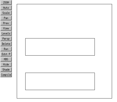
To develop such a set of projections, let's first start with a front (XY) projection of our box. Recall that a front or XY projection is a parallel projection in which the viewer is situated some arbitrary distance out along the Z axis (looking into the screen). Adjusting our drawing border to reasonable values, this front projection could be accomplished in this way:
GLOBAL DRAWING MODULE testdraw();

FLOAT xmin;
FLOAT ymin;
FLOAT xmax;
FLOAT ymax;
CONSTANT INT frontview=0;
CONSTANT INT topview=1;
CONSTANT INT rightview=2;
CONSTANT INT isoview=3;

BEGINMODULE

  part(#1,boxnorotg(8, 2, 4, 0, 0, 0, 0));
  part(#5,frontview());
  xmin:=-1;
  ymin:=-1;
  xmax:=10;
  ymax:=10;
  lin_free(#6,vec(xmin, ymin), vec(xmax, ymin));
  lin_free(#7,vec(xmax, ymin), vec(xmax, ymax));
  lin_free(#8,vec(xmax, ymax), vec(xmin, ymax));
  lin_free(#9,vec(xmin, ymax), vec(xmin, ymin));

ENDMODULE

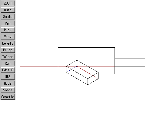
So far, so good. However, if the top view is projected in what would appear to be a straightforward way, by moving it up 4 units on the Y axis:
part(#2,boxnorotg(8, 2, 4, 0, 4, 0, 1));
then the following odd situation arises when the active module is compiled (and the Auto button pressed to autozoom):
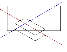
If the "Run" button is then pressed, the following final result occurs:
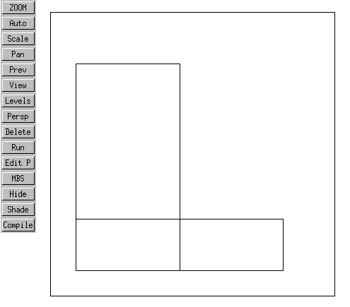
What is happening is this: In the first view above (after compilation and autozoom, but before Run) the contents of the graphical database are being displayed. In the GM graphical database, two boxes have been created, one above the other.
At "Run," as our box routine specifies, an XY view is created for the first box in which the viewpoint is out along the box's Z axis. This is the front view we saw originally. Then another view is created, a YZ top view of the second box. In this view, the second box is seen from a point somewhere out along the Y axis (that is, looking down from above). However, the fact that this is a "view" means that this Y axis will be rotated such that it points out of the screen (or into the screen, depending on how you look at it). In doing this translation, Varkon makes the box's X axis point up and its Z axis point to the right.
At this point, I gave up with this method and developed the method described in Section 9.1. "By Positioning the Model".
With the exception of any material noted as being in the public domain, the text, images, and encoding of this document are copyright © 1998 by David M. MacMillan.
The author has no relationship with Microform AB, and this Tutorial is neither a product of nor endorsed by Microform AB.
"Varkon" is a registered trademark of Microform AB, Sweden.
This document is licensed for private, noncommercial, nonprofit viewing by individuals on the World Wide Web. Any other use or copying, including but not limited to republication in printed or electronic media, modification or the creation of derivative works, and any use for profit, is prohibited.
This writing is distributed in the hope that it will be useful, but "as-is," without any warranty of any kind, expressed or implied; without even the implied warranty of merchantability or fitness for a particular purpose.
In no event will the author(s) or editor(s) of this document be liable to you or to any other party for damages, including any general, special, incidental or consequential damages arising out of your use of or inability to use this document or the information contained in it, even if you have been advised of the possibility of such damages.
In no event will the author(s) or editor(s) of this document be liable to you or to any other party for any injury, death, disfigurement, or other personal damage arising out of your use of or inability to use this document or the information contained in it, even if you have been advised of the possibility of such injury, death, disfigurement, or other personal damage.
All trademarks or registered trademarks used in this document are the properties of their respective owners and (with the possible exception of any marks owned by the author(s) or editor(s) of this document) are used here for purposes of identification only. A trademark catalog page lists the marks known to be used on these web pages. Please e-mail dmm@lemur.com if you believe that the recognition of a trademark has been overlooked.
Version
1.3, 1998/06/17.
Feedback to dmm@lemur.com
http://www.database.com/~lemur/vk-3din2d2.html
Go to the: