This Barth Journal entry is in its subject pretty minor - a part of the machine you'll never ordinarily see. But it leads out into several other issues: presentation of original data, CAD models and drawings, and a parts symboling scheme. It also shows a design flaw that could have been avoided.
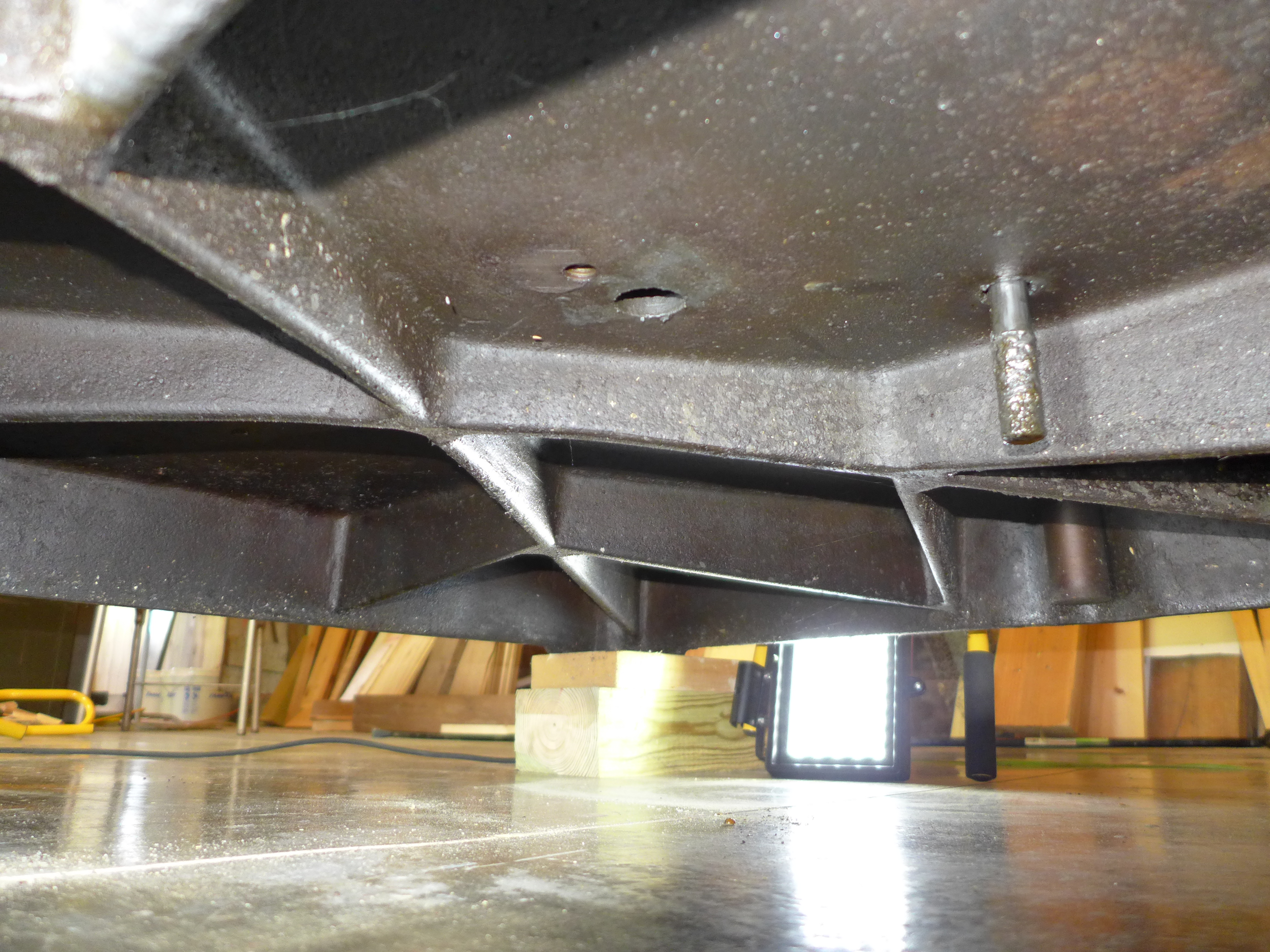
With the Barth now five inches up in the air - as high as I plan ever to lift it - the opportunity to photograph its underside was not to be missed. Here it is from the left (operator's left) side:
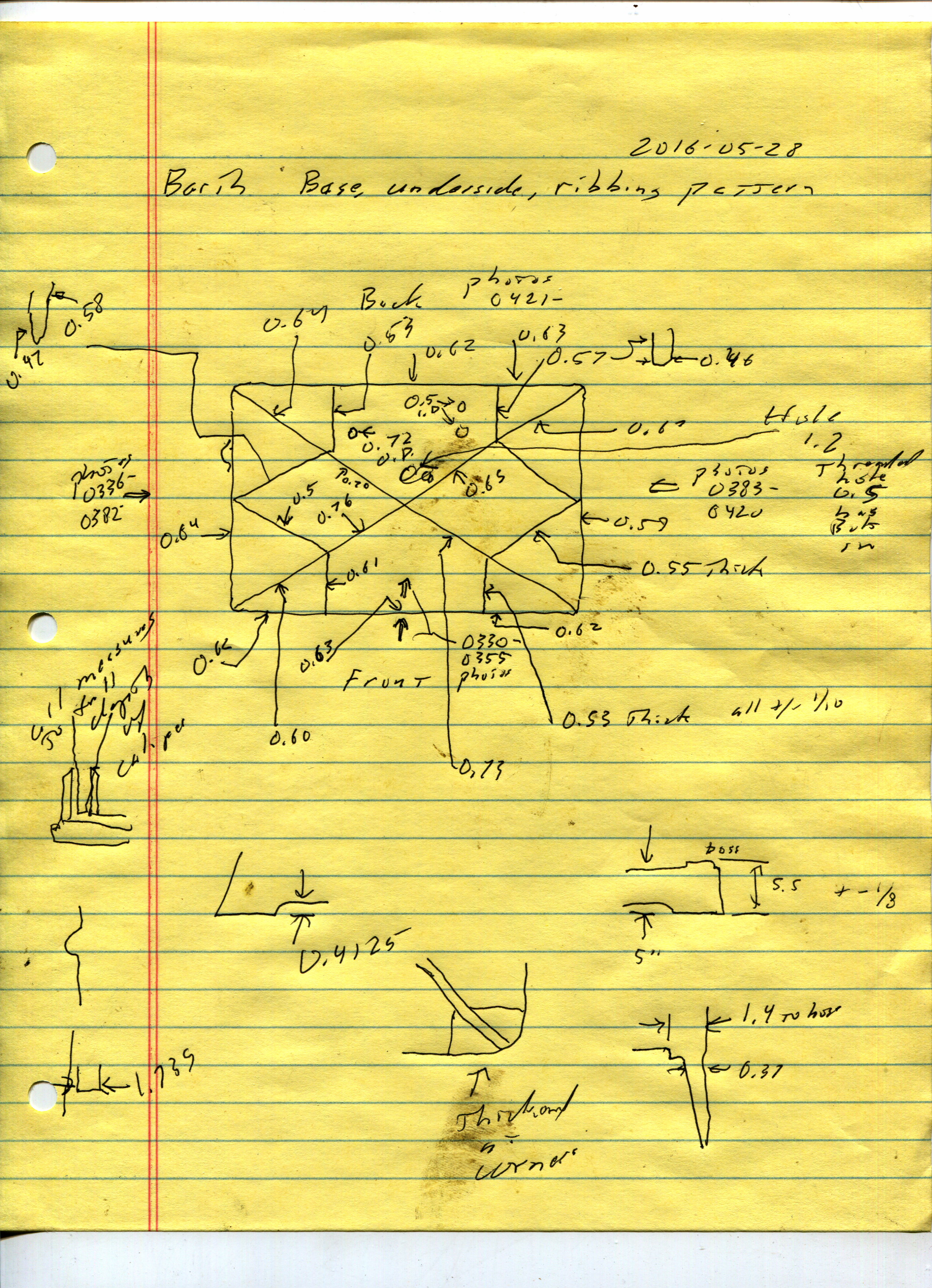
Here's the ribbing pattern (for now just cropped from my crude sketch):
But here is a design flaw not apparent if you just see the Barth from above. The placement of the major bolts which attach the two vertical "Standards" (left and right sides of the machine frame) to the Base is such that their threaded holes are right on top of the main diagonal ribs. This means that these ribs are cut, pretty severely, for about half of their vertical thickness. This could have been avoided at the design stage. (The corners are reinforced, and there is enough cast iron that it isn't a problem, but it isn't right. Other ribs are cut by other holes as well (see the first photo above).
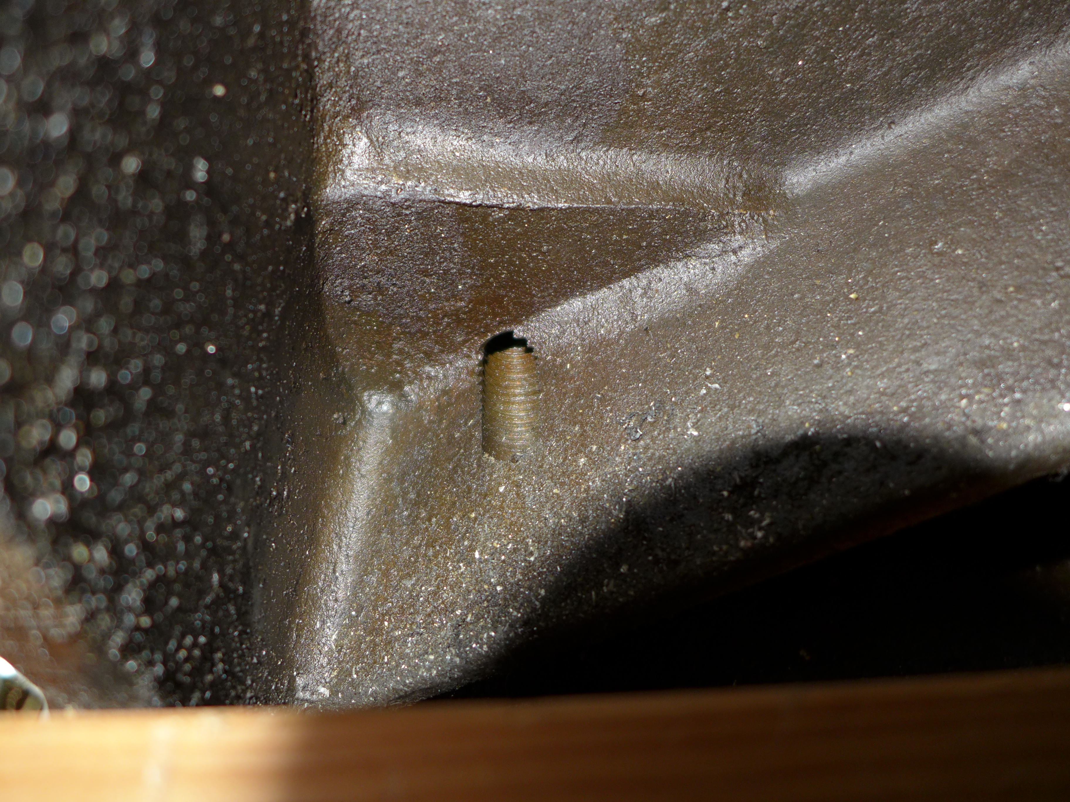
Here's the flaw as seen on the front right corner of the machine. The photo below left shows the back side of the main diagonal rib to this corner (so the left of the photo is the operator-right side wall of the Base). It's drilled (and tapped) for a serious portion of its depth. The photo below right shows the front side of this same rib (so the right of the photo is the front side wall of the Base).
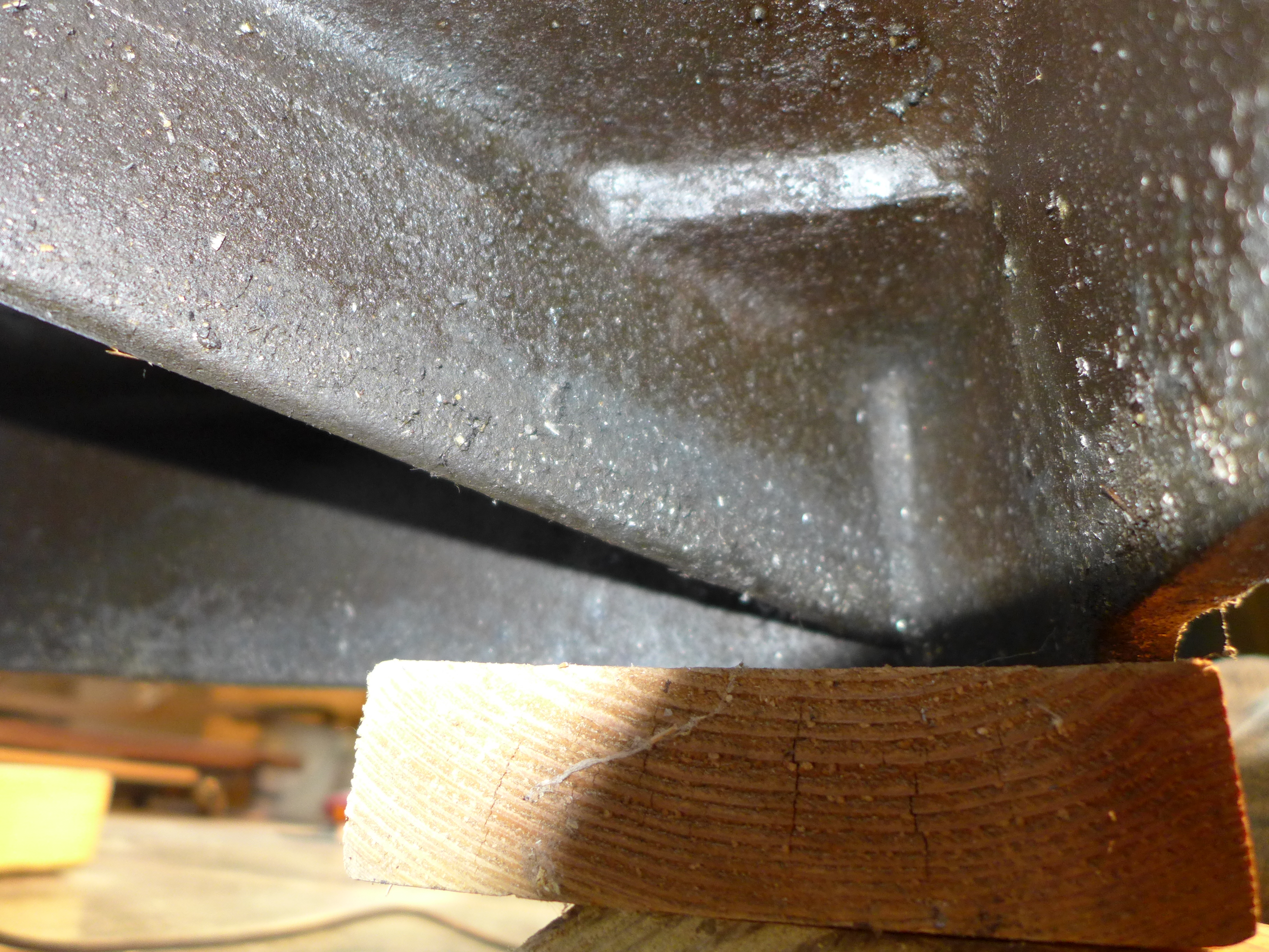
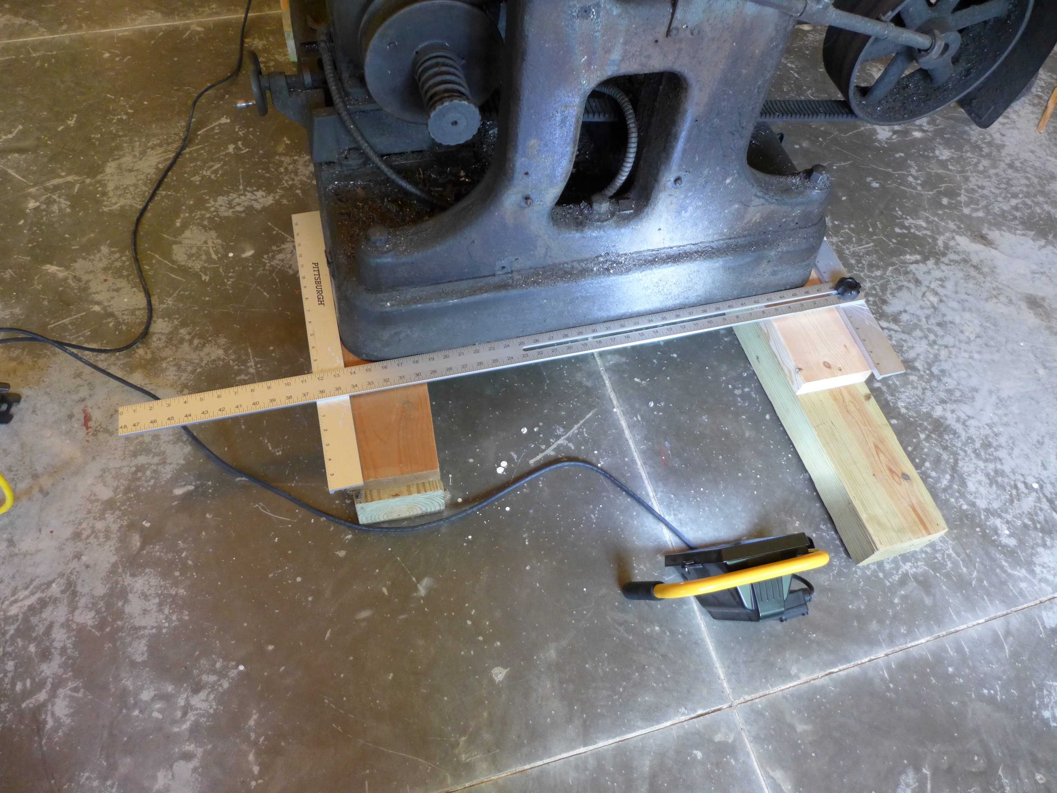
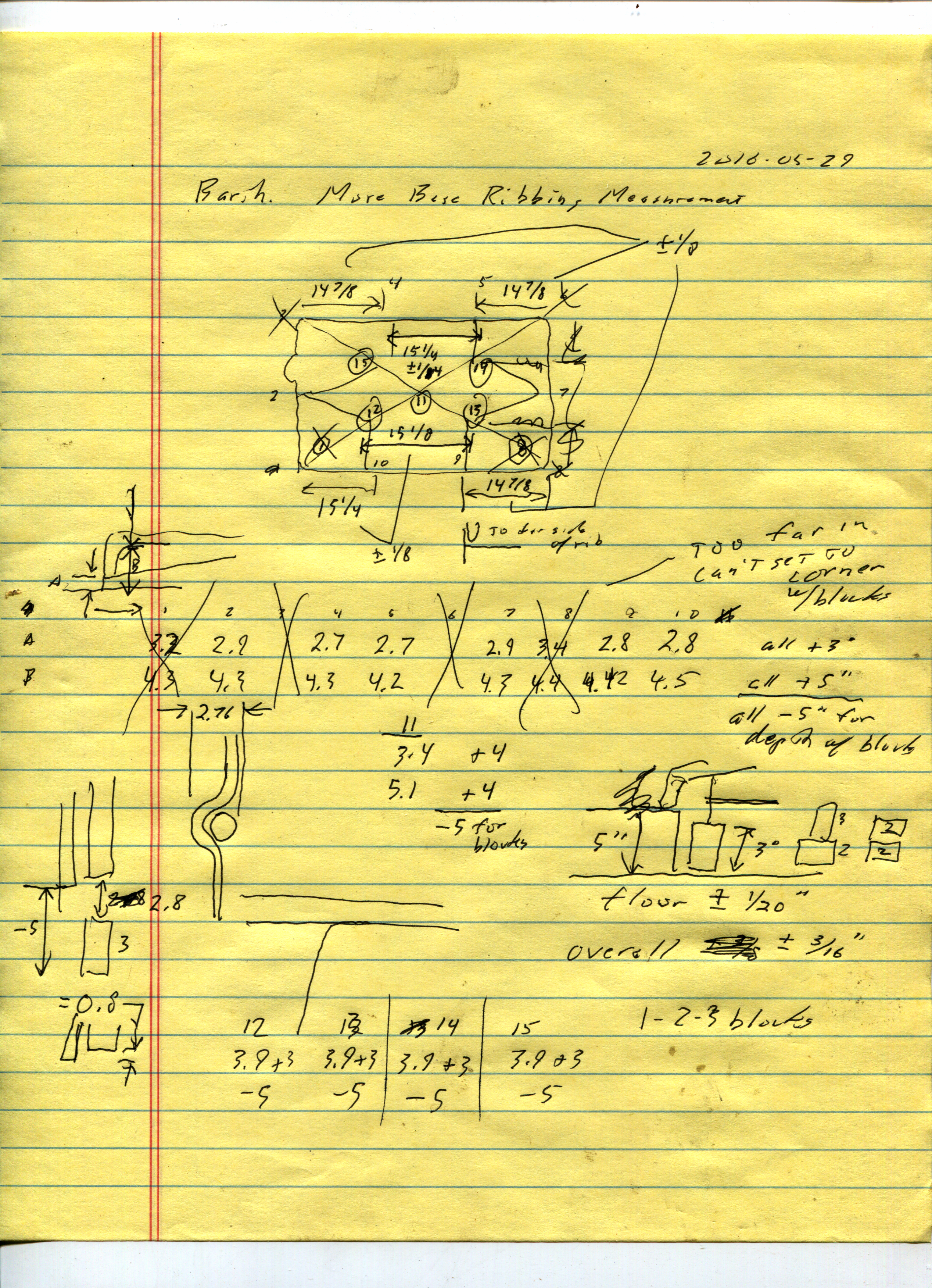
I measured the overall dimensions of the base using an asembly constructed from two large adjustable squares (yes, from Harbor Freight). For smaller features I used 6" digital calipers. For measuring the depths of the ribs and the internal height of the base, I used telescoping bore gauges from the floor up (actually, from 1-2-3 blocks set on the floor because my telescoping gauges weren't long enough). With these measurements in hand, I subtracted out the height of the wooden blocks the machine was resting on (which were surprisingly close to 5 inches).
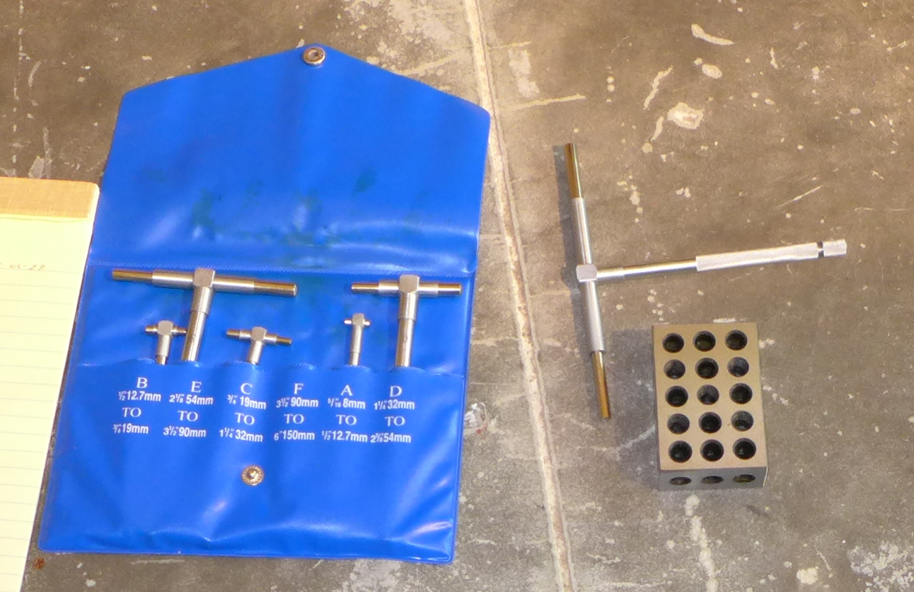
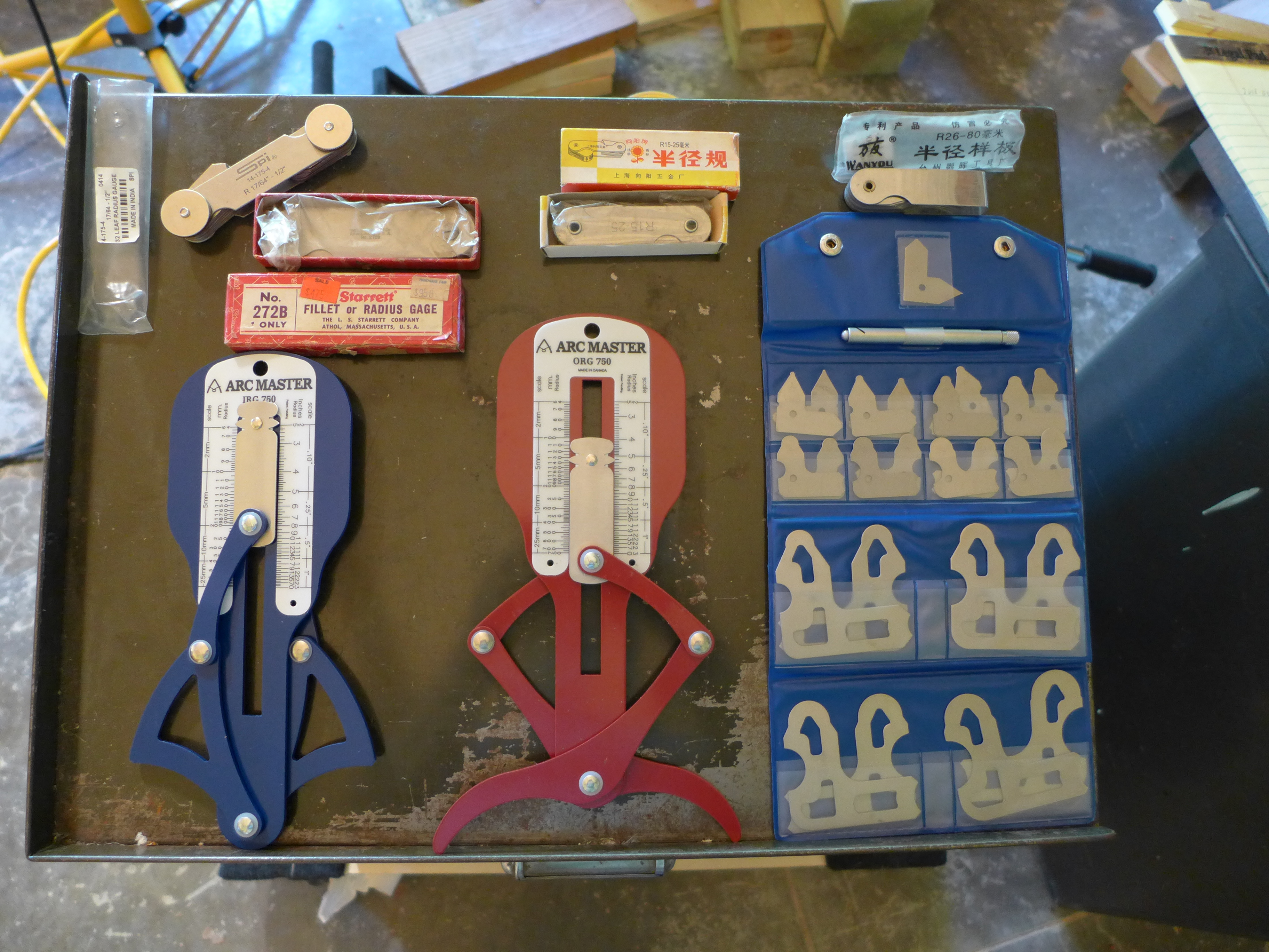
I measured the radii (a few days later, on 2016-06-05) using both fixed and variable radius gauges. Here's my somewhat random collection of such gauges:
To measure the Base, I ended up using the Arc Master ORG-750 (the red complicated looking gauge), the Wanyou brand 26-80mm gauge (converting to inches; it's hard to find native-inch gauges in this size), and the nameless set of fixed gauges in the blue folder.
But these measurements bring up a basic ethical problem: Everything I say about the Barth could be wrong in (at least!) two different ways. First, I might simply err. I'm sure I will; I'll try to correct things when I do. Second, though, I might lie. In fact, I will lie, although not with malicious intent. Technical documentation is technical narrative - it's a story we tell about the machine. It simplifies and homogenizes; it rounds off the rough edges. A measurement may be 0.63 inches, but I "know" that it "really" must have been 5/8" on the original engineering drawing - so I simplify it to 5/8". Maybe I'm wrong when I do so - but if I just say 5/8", how do you know?
You don't have access to the original machine. So if you are to stand any chance at all in correcting my lies, you'll need at least access to my original data (primarily handwritten notes and digital photographs). Psychologically, this is hard to do - for both of us. For one thing (on your part), this is mind numbingly boring material. Oh, another picture of cast iron (I take thousands); oh, another scribbled dimension. For another (on my part), it is embarassing. I can't draw, my printing is unreadably ugly (I gave up on proper script years ago - remember, before I retired I basically typed for a living), and (worst) I make mistakes. In ink. These are not the notebooks of DaVinci.
But I've come to the difficult conclusion that in order for this presentation of the Barth to rest on foundations as sound as I can make them, I must make this information available. So here it is, "warts and all," in a set of plain images: ../../ Notes & Photographs.
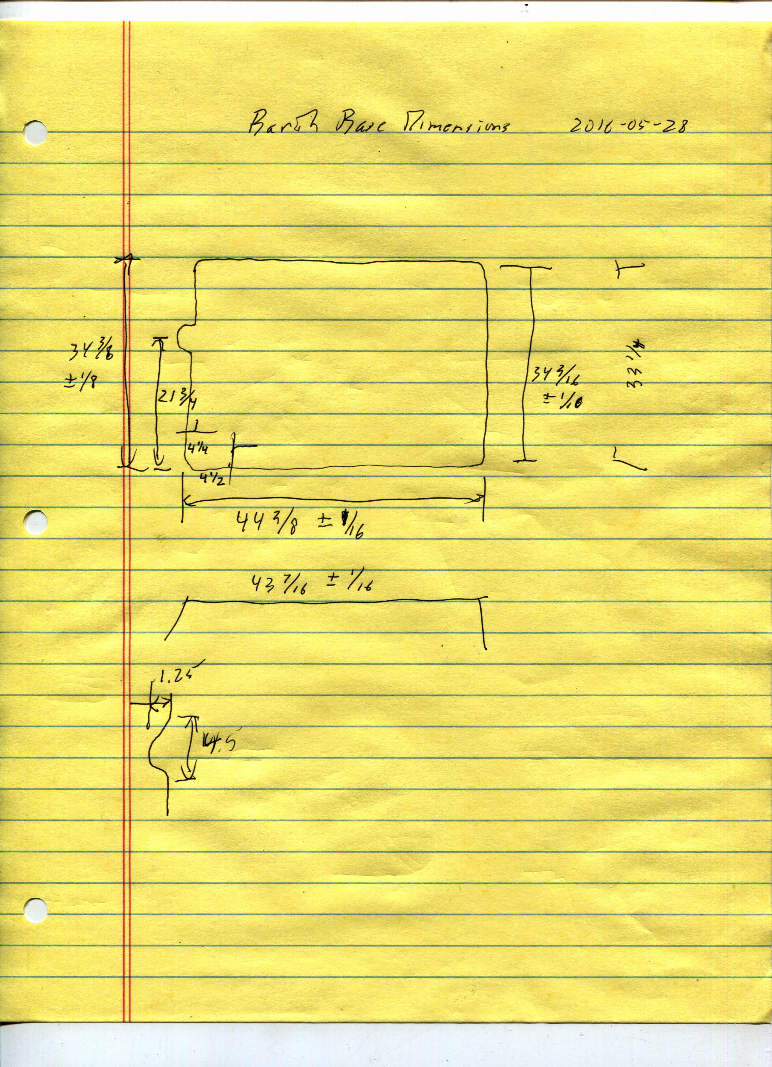
Here are my notes (so far) for the dimensions of the base, and its ribs:
I've also had to develop an approximate scale for estimating the uncertainty of my measurements. This is a general topic, part of the Notebooks On the Reverse Engineering of Big Old Machines: Estimating Your Uncertainty.
The measurements here are "UL6" on this scale (measurements in place, using common precision measuring tools, with only modest expectations).
For reference, the base casting of the No. 3 1/2 Barth, at its bottom, exclusive of projections, is 44 3/8" x 34 3/16", both +/- 1/16 inch. (Note: These dimensions were certainly designed in a fractional inch system, and therefore are properly expressed in fractional inches.)
Given a set of dimensions, and at least some general idea of how to re-interpret them back into an engineering design, the next step (if it was 1886) would be to create engineering drawings. It is 2016, so the next step is to create a 3-D CAD model. (Though I am far from convinced that this is really an improvement. Often I am on the verge of discarding CAD-as-it-is-today and going back to my very nice manual drafting tools.)
Of course, you may ask why these measurements, and consequent drawings and/or CAD models, are necessary at all. After all, the machine exists, and all we need to do is to learn how to run it. There are two reasons.
The first is an optimistic one: so that someday we can build another Barth. This is of course crazy, which does not make it any less appealing.
The second is a practical one: the Barth Operator's Manual will need illustrations. I can't draw. Photographs won't always work, because when you need to see inside the machine you can't just take a saw and torch and cut it away. (Actually, once you could. Technical illustration reached a high point in the 1930s, when they would simply take a hugely expensive item such as an aircraft engine, cut it up, photograph it, and retouch the photos to show exactly what you needed to see. We can't match that now - not because we don't have good illustrators, or because modern tools are inferior, but because then and now good technical illustration is expensive. We're no longer willing to pay for it.)
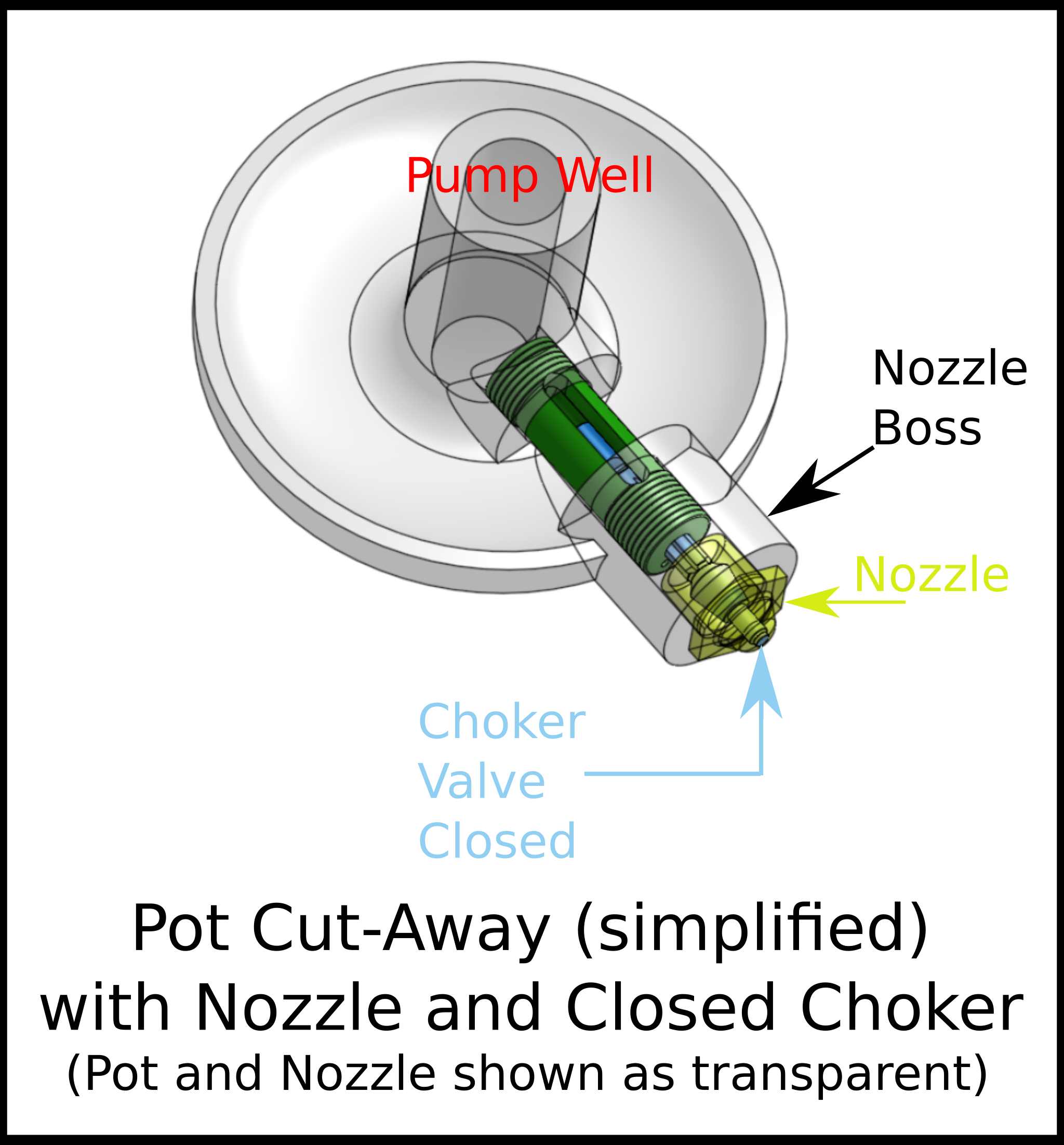
Anyway, CAD models allow illustrations which show the guts of a machine. I don't have an example yet for the Barth, but here's one for the Thompson Type Caster which shows parts of the machine that can't normally be seen.
CAD models introduce the issue of what CAD system to use. The problem is twofold:
First, there is no universal standard, open or proprietary, for CAD models which preserves the full functionality (including history) of the design. IGES and STEP aren't sufficient. Solidworks' format and DWG are neither sufficient nor open. Nothing else even comes close. This means that any use of CAD from its origins through the present (and forseeable future) is doomed. We can read engineering drawings from 1916. Our CAD models of 2016 will be black holes to the engineers of 2116. In a way this simplifies things: use whatever works, and make darned sure that you generate real 2-D engineering drawings (you need them, still, for proper GD&T anyway).
Second, there is no good open source 3-D CAD (for a 2014, pre-Onshape, review see the now slightly obsolete CircuitousRoot Notebook Reviewing the Options for Digital Drafting and Modeling). There are now good free (but not open) 3-D modeling options. But until very recently the only way to really get into very good 3-D CAD was to plunk down many thousands of dollars to get SolidWorks.
There's now (2016) an attractive alternative: Onshape. It's still in its early stages, and isn't yet quite as capable as SolidWorks, but it's improving very rapidly. More importantly, it also has an extremely usable free-cost plan (full access, but limited as to the number of models). I'm actually subscribed now at the "Professional" level (that is, paid, for a single individual), but I got along at the free level for over a year.
The thing about Onshape is that it's "cloud only." This is Newspeak for a return to 1960s datacenter technology. It runs on their servers (actually, I think it runs on Amazon's servers) and you access it via your browser or a mobile device app.
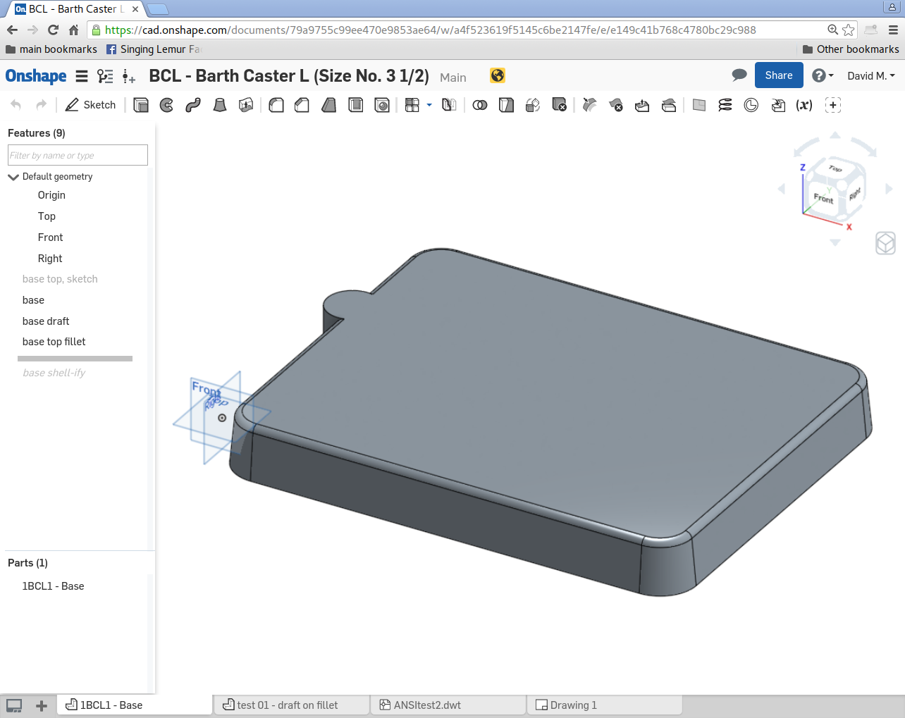
This actually makes it very easy for me to share the models. You can view them read-only even if you don't have a (free or paid) Onshape account. Click on this link:
https://cad.onshape.com/documents/79a9755c99ee470e9853ae64/w/a4f523619f5145c6be2147fe/e/e149c41b768c4780bc29c988
and you should get to a screen which looks like this:
(As I write this Journal entry, the Onshape CAD model of the 1BCL1 Base is far from finished.)
If you do have an Onshape account, just search the Public models for "BCL - Barth Caster L" and you should find it. You can then copy it to your own workspace and, if you wish, modify it. Although Onshape doesn't have a convenient place for me to say so, it is licensed under the Creative Commons Attribution-ShareAlike 4.0 International license.
(As an aside, the Barth 3-D model "BCL" is one of the various Open-Source Hardware Projects on CircuitousRoot.)
The final (well, final for now) issue brought up by drawings and models is one of parts symboling systems and part and assembly names. Once you start drawing or modeling parts, you must identify them and name them.
To the best of my present knowledge the parts symboling (that is, part numbering) system used by ATF for the Barth has not survived. (At least one general arrangement drawing survives, but I haven't seen it yet.) Some of the casting have (barely legible) numbers on them, but these are problem casting identification numbers, not part numbers.
So I'll have to create a system as I go along. I'll use a version of the scheme developed by Monotype - based most closely on the variant they used for the Monotype-Thompson Type-Caster. (For more on the general topic of parts symboling systems, including a study of the Bancroft/Monotype system, see the CircuitousRoot Notebook on Parts Symboling Systems.
In general terms, the system used here will have a three-component symbol for each part: number letter-code number. The letter-code uniquely identifies the part as belonging to the Size No. 3 1/2 Barth: BCL. ("BC" for "Barth Caster," 'L' because if you enumerate all of the sizes of the barth from No. 1 = 'A' onward, the No. 3 1/2 is the 12th, or 'L'th model). See the CircuitousRoot Project Organization Notebook for further discussion.
The number before the "BCL" indicates a general set of related parts (e.g., all of the parts of the machine frame). I'll follow later Lanston Monotype practice and call this the "Group."
The number after the "BCL" is the number of the individual part within the Group. Thus, the Base is "1BCL1," the two Standards rising from the Base are "1BCL2" and "1BCL3", and so forth.
As to names for parts, we have imperfect guidance. Some names survive in the oral tradition handed down from ATF through Theo Rehak and the Dale Guild. When I know what this is, I'll follow it. For other parts, the patents provide a clue. Often, though, I'll just have to make something up.
Aside: there are also conflicts. For example, the flat table-like surface on which an operator might put his or her tools is called the "Table" in the patents. ATF/Rehak tradition calls it the "Apron" instead. But, confusingly, the patents use the term "Apron" to name the device which we would normally call the "Nipple Plate" (and which is called the Nipple Plate in the surviving ATF engineering drawing for it ).
The numbers used in the basic patent for the Barth, US No. 376,765 to Barth & Lietze, 1888, are consistent throughout the many drawings in the patent. I'll often make informal reference to them when identifying parts, prefixing the reference with "pat" (thus 1BCL1 is also "pat1"). This may be of assistance if you're reading through the patent trying to understand the machine.
All portions of this document not noted otherwise are Copyright © 2016, 2022 by David M. MacMillan.
Circuitous Root is a Registered Trademark of David M. MacMillan.
This work is licensed under the Creative Commons "Attribution - ShareAlike" license, version 4.0 International. See http://creativecommons.org/licenses/by-sa/4.0/ for its terms.
Presented originally by Circuitous Root®

