This posting really isn't finished. You'll find some loose ends and notes to myself. But it has been sitting in the queue for over a year now. I'm unlikely to revisit and finish/fix it, yet there is enough material in it that it might be interesting to some. So here it is, acknowledged flaws and all.
Other? This post grew out of the work reported in my "Instagram vs. the Ents" Workshop Update, which looked into two ways to center a punch mark in a workpiece held on the faceplate or in the four-jaw chuck of a lathe. Here we have a more detailed look into these and related devices. It deliberately excludes the category of devices that I'm calling, generically, (Lever) Center Indicators. These get a writeup of their very own.
I've tried to organize the devices into logical categories here (for some definition of "logic"; there is room for disagreement here):
Names are hard (anyone ever tasked with coming up with a trade name for a product would confirm this), but they're also important. Unfortunately, here there is no good solution. The devices discussed here never had any generally accepted name (or even names). This leaves the field wide open; you can call it/them whatever you wish. However, I will argue in the section "What To Call These Devices?" that the newly popular name "pump center" is not a good choice.
It is easy, in looking at all of these clever devices, to get hung up on precision and accuracy. As a sanity check, remember that any machining technique which depends upon layout, punch marks, and the like is in most traditional machining textbooks considered only semi-precision work. These methods are also only semi-accurate. (Accuracy and precision are not the same.)
These center indicators can trip you up because many of them can achieve a much greater level of precision than the accuracy of the underlying layout and punch mark placement. For example, as discussed in (Lever) "Center Indicators", I was able to locate a punch mark to a precision of 0.000,3" runout on the center indicator, but the locational accuracy of the punch mark itself was an order of magnitude less - perhaps 0.003 or (likely) worse.
Truly accurate work by traditional methods employs other methods. The one most commonly cited in older texts on accurate tool work is that of the Toolmaker's Button. This isn't the place for a full investigation of this technique, but it may be useful to give a brief overview.
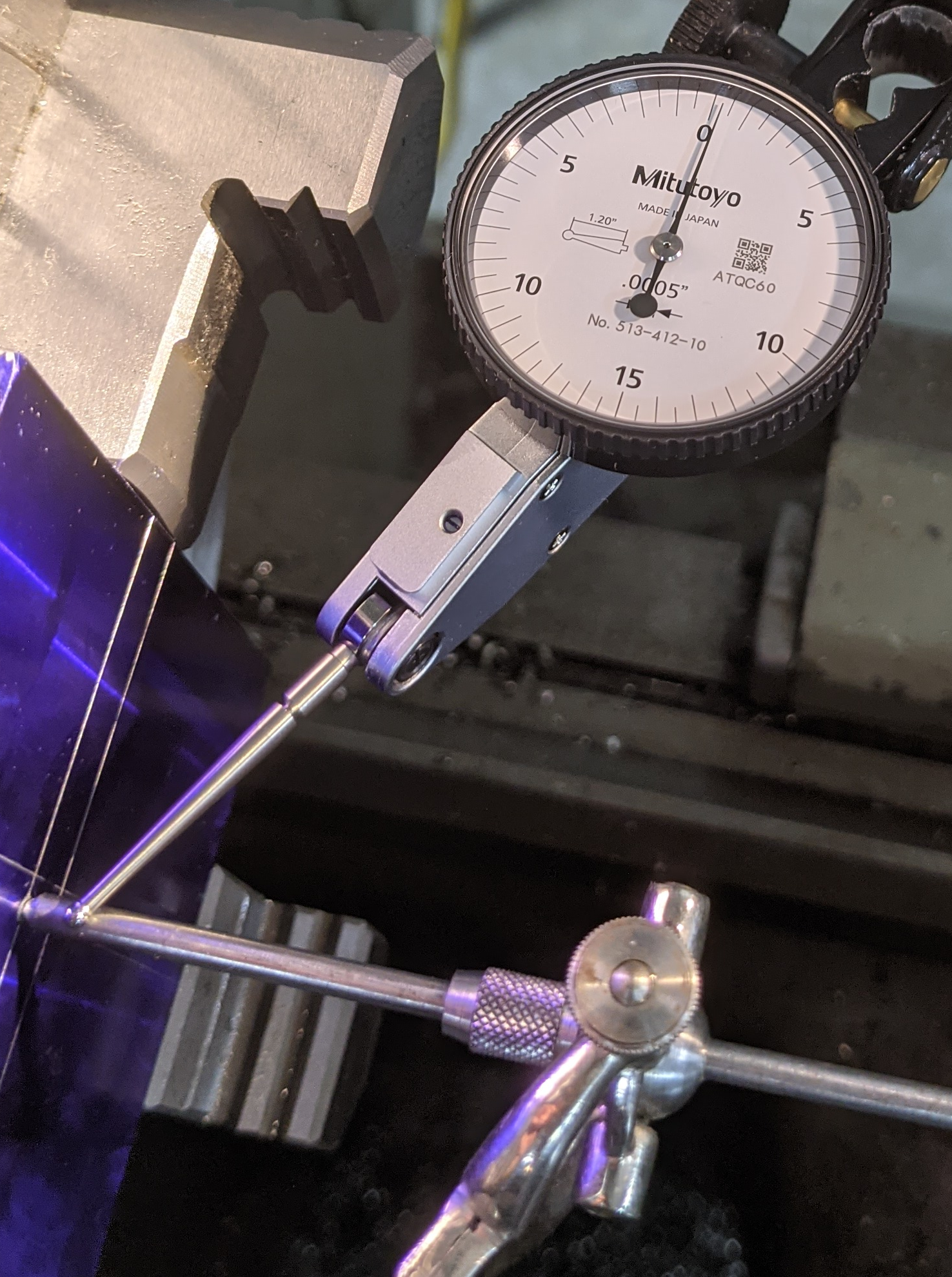
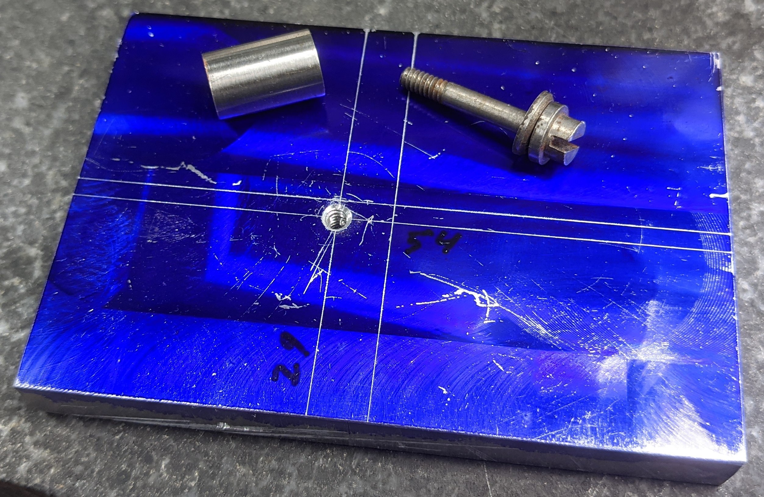
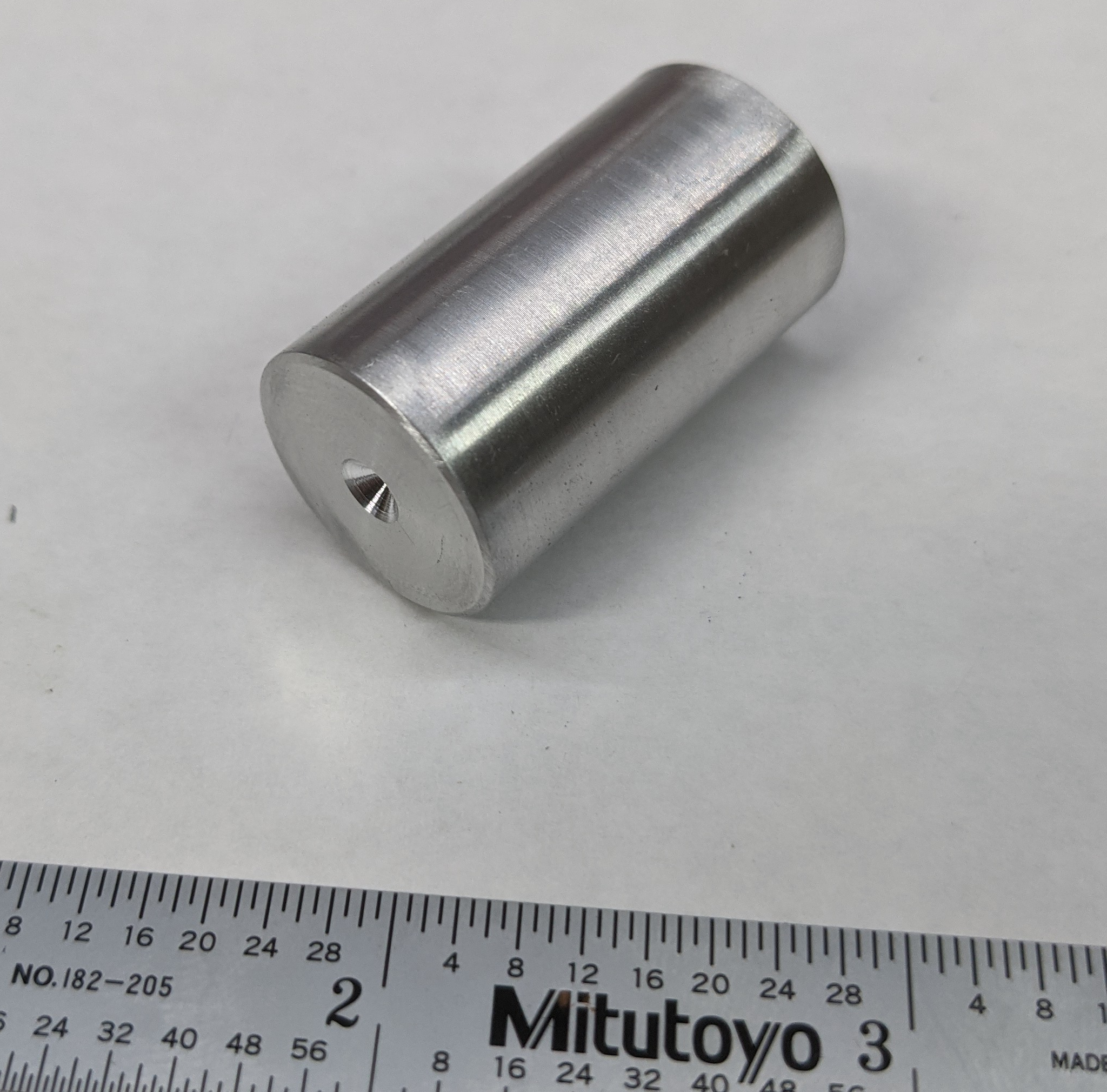
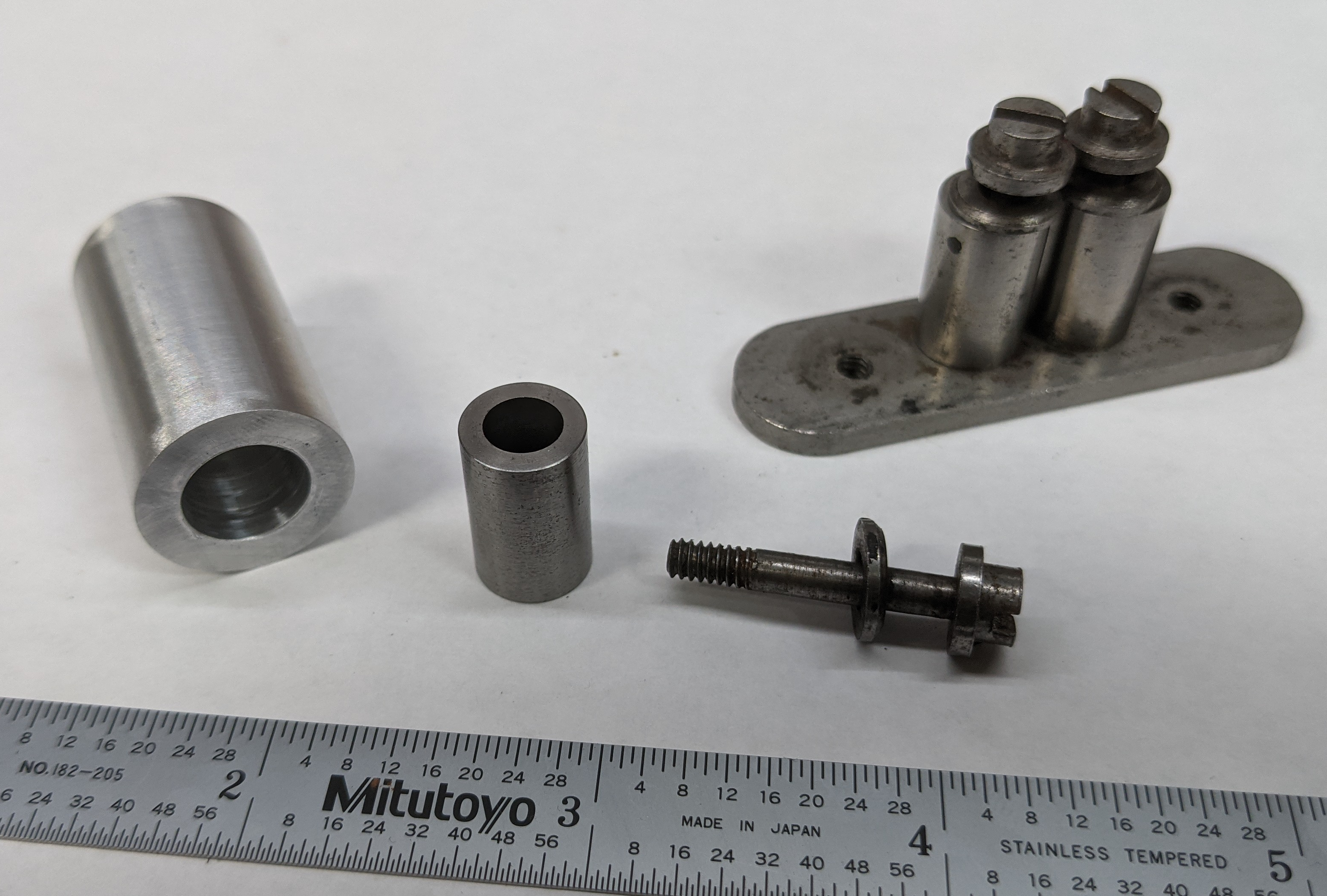
A Toolmaker's Button is just a precise and accurate small hollow cylinder of steel, together with a screw for holding it down. Here are two sets; the one on the right was manufactured commercially, the one on the left may (or may not) be shop-made. Each set has four buttons on a stand. The stand itself is not part of the button in use, but the screw is.
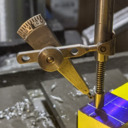
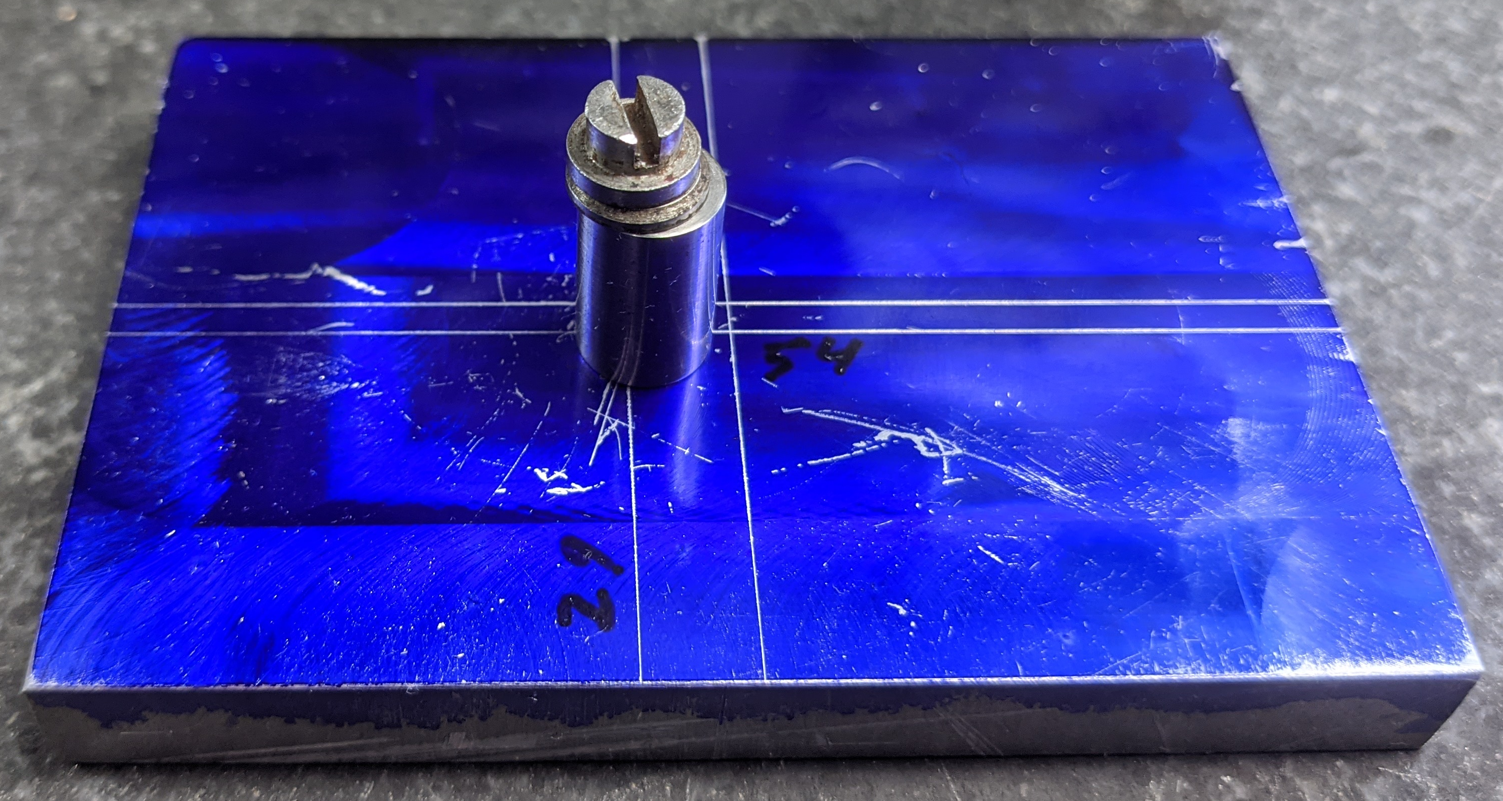
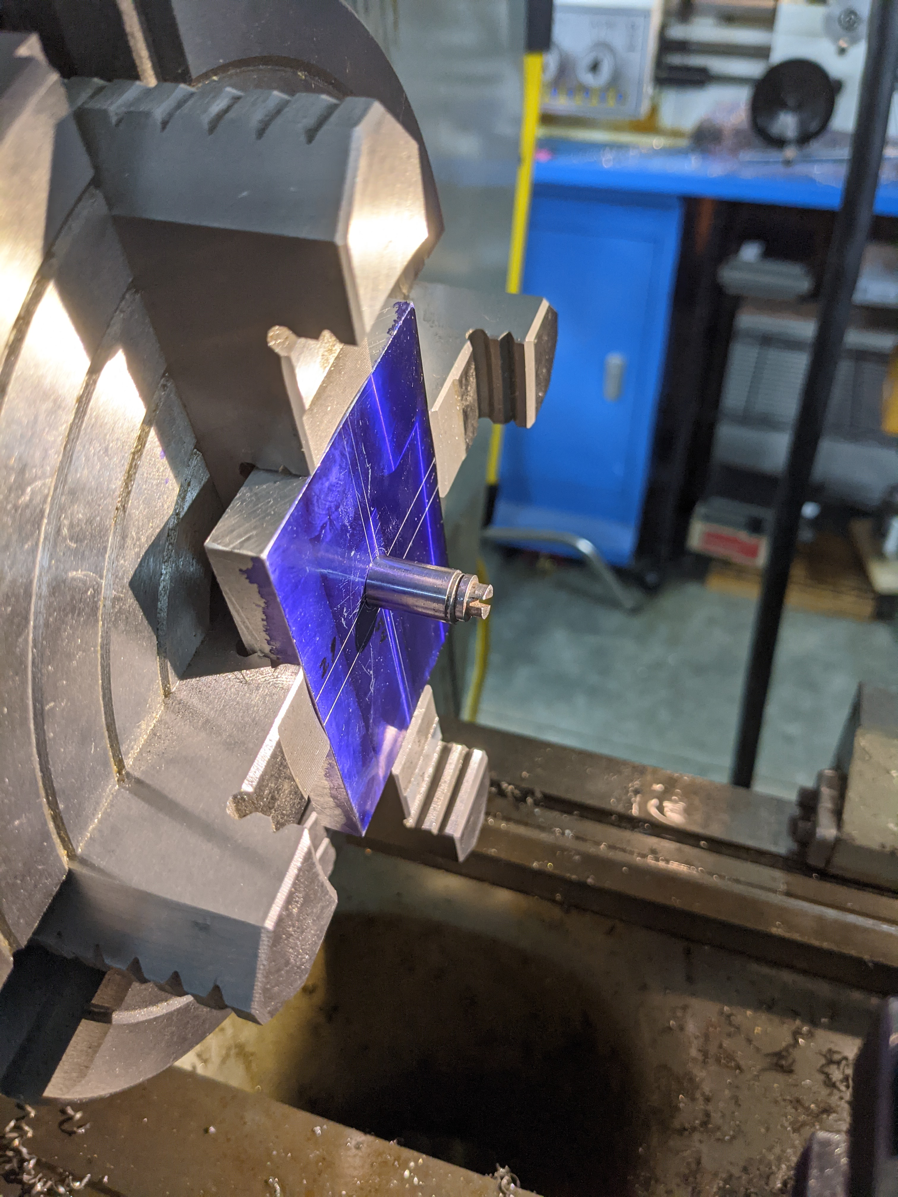
To use a toolmaker's button to locate a feature (e.g., to let you mount a workpiece on a lathe faceplate so that you can drill a hole at some particular location very accurately) you start by locating the feature approximately. Ordinary layout methods are fine. The location doesn't have to be perfect; close is ok. Then drill and tap a hole at that location with the same thread as the button's screw. See below, left. (In this photo I've just recycled the example piece from the center indicator test, above, by drilling a hole at the punchmarked location. The layout here isn't very beautiful, but it's good enough for the job.) Assemble the button at that location. Snug up the screw, but don't tighten it down. See below, right.
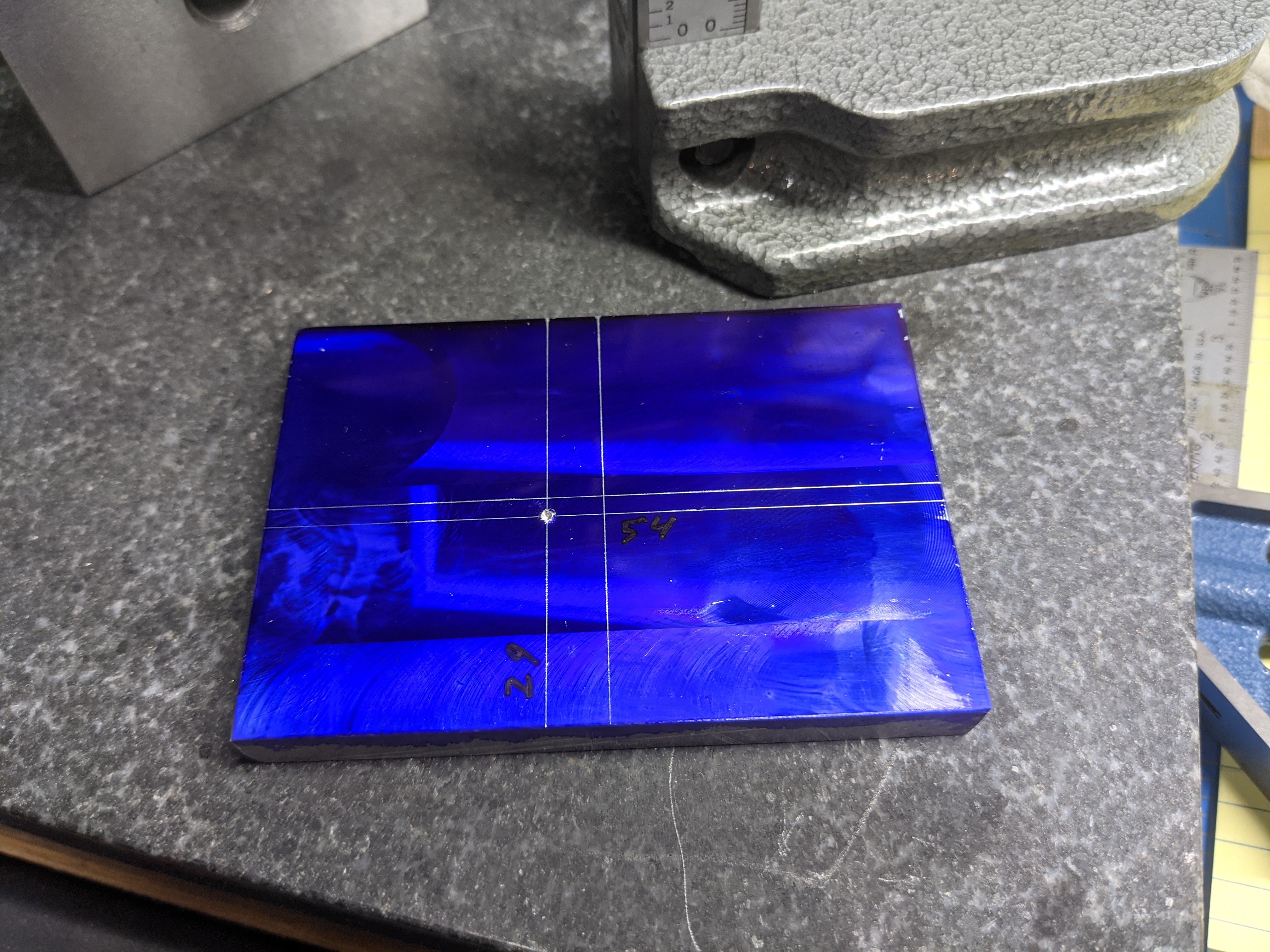
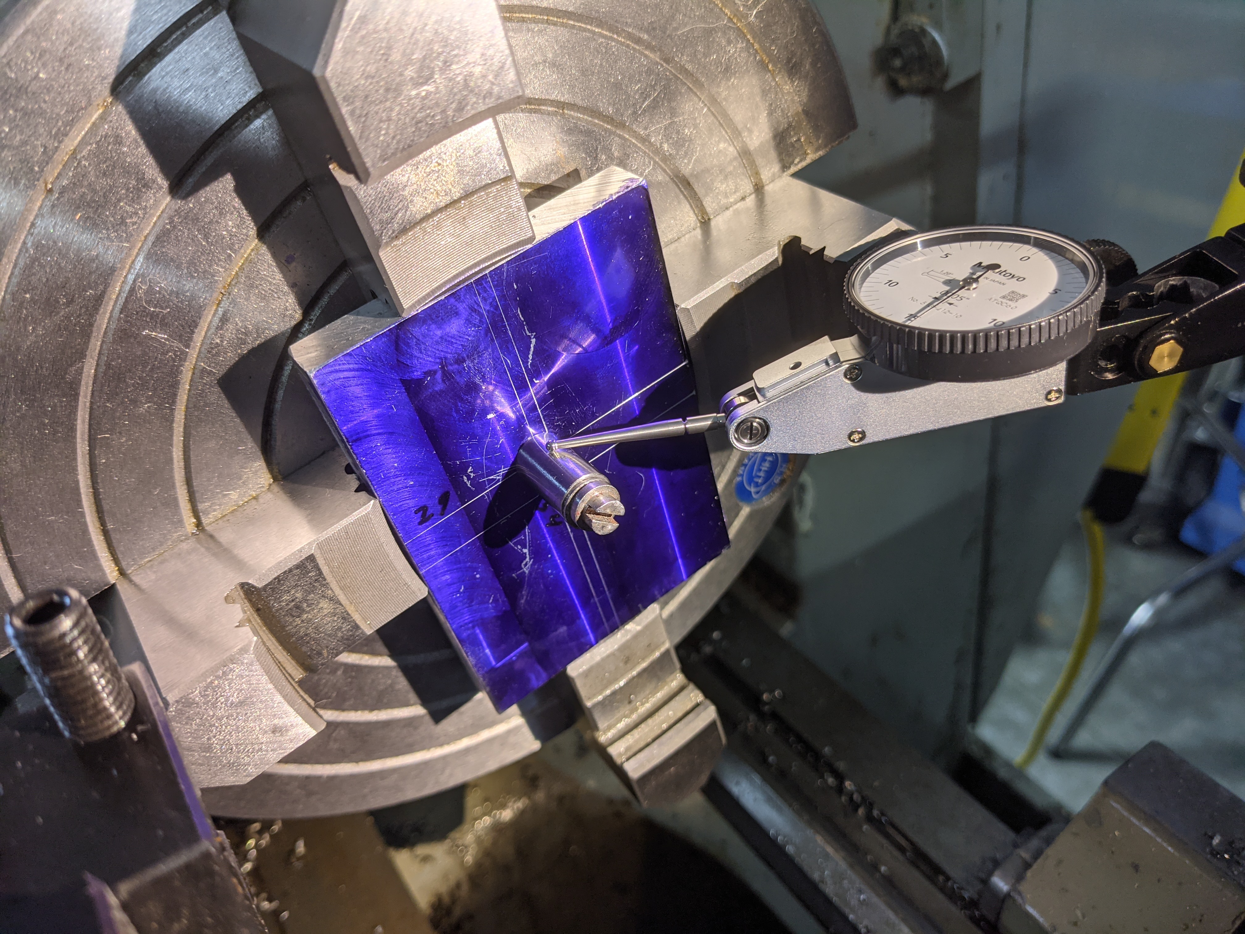
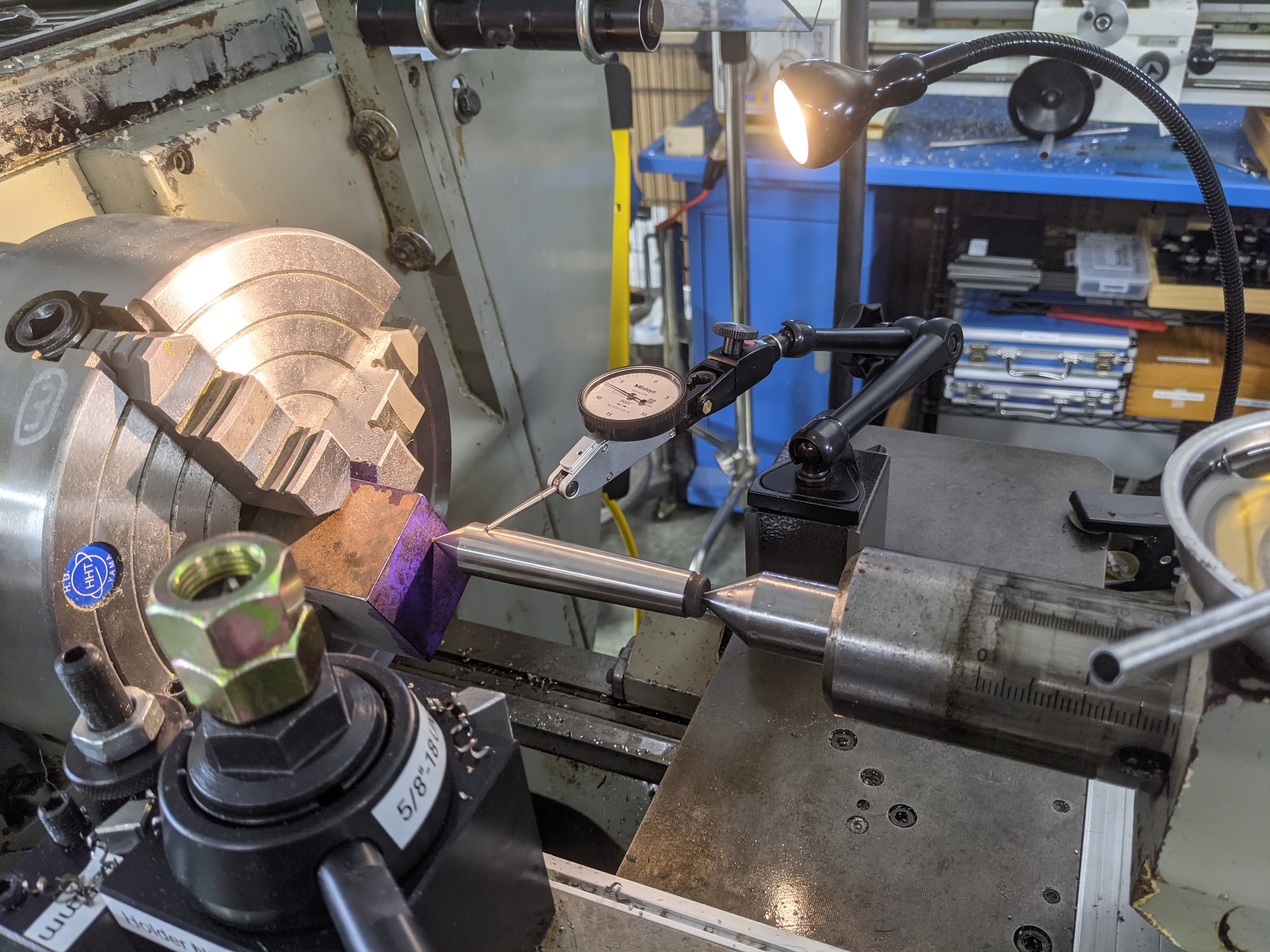
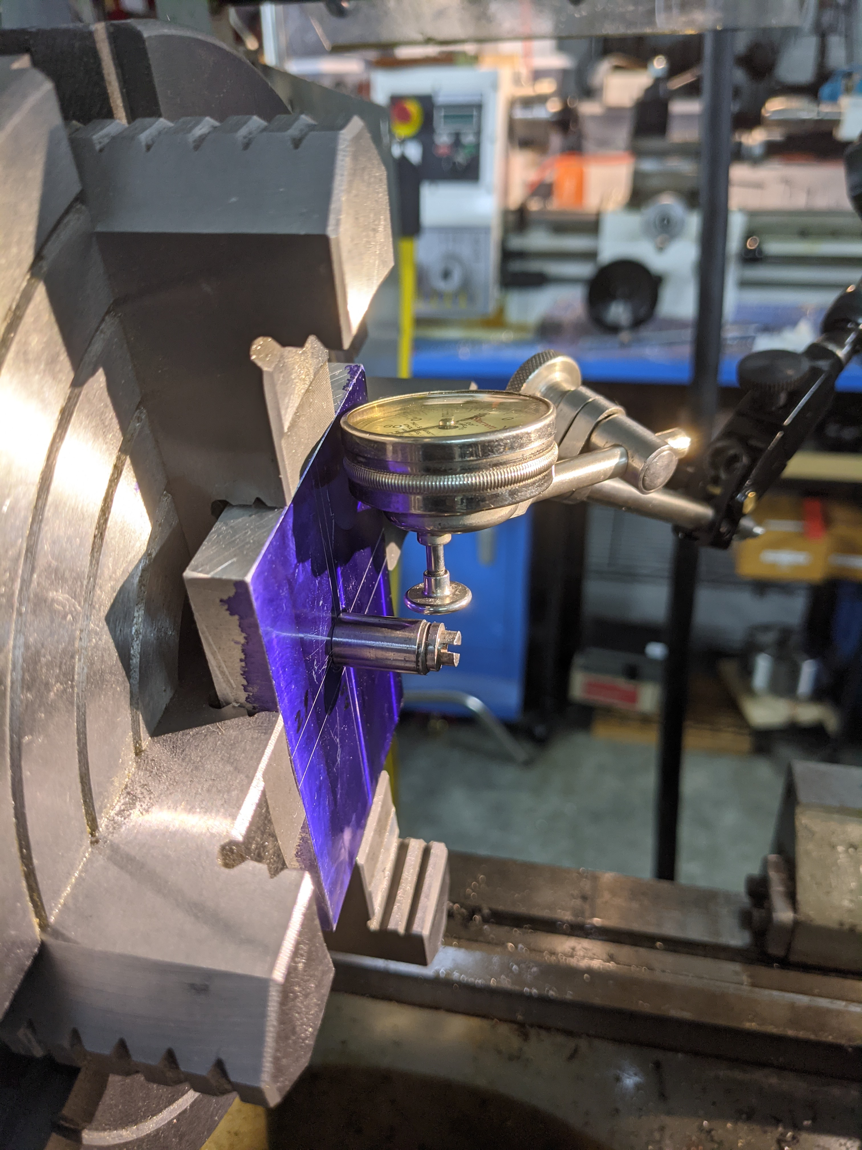
Next, knowing the diameter of the button, use the method of your choice to adjust its location such that its centerline is at the desired location on the part. In the photo below left I'm using a hacked-together combination of an adjustable parallel (set off-camera to the correct width) and a height gauge. (Note: The figure on the height gauge, 59.08 mm, is correct. I'm using an inch-system toolmaker's button for a metric layout.) Tighten up the button. Finally, put the workpiece on the machine (a 4-jaw chuck on a lathe, in this example) and use a test indicator to adjust the workpiece so that the button runs true.
Then (not shown) remove the button and perform the machining operation to create whatever feature you're creating at this location. In the example shown here, the axis of the button is within a couple of ten thousandths of an inch of the centerline of my lathe, which is both more precise and more accurate than is possible with layout and punch mark based methods.
We return you now to your regularly scheduled programming...
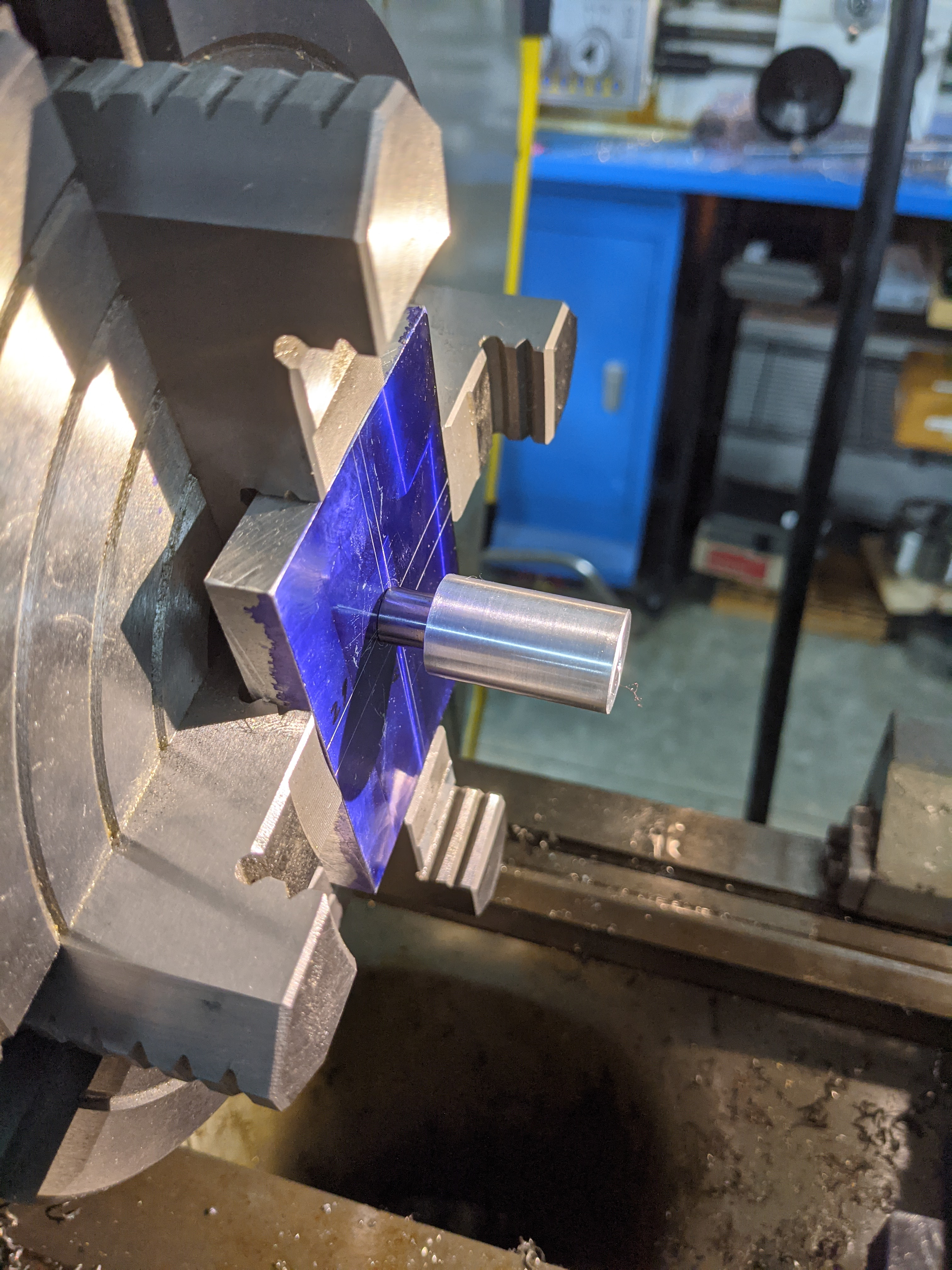
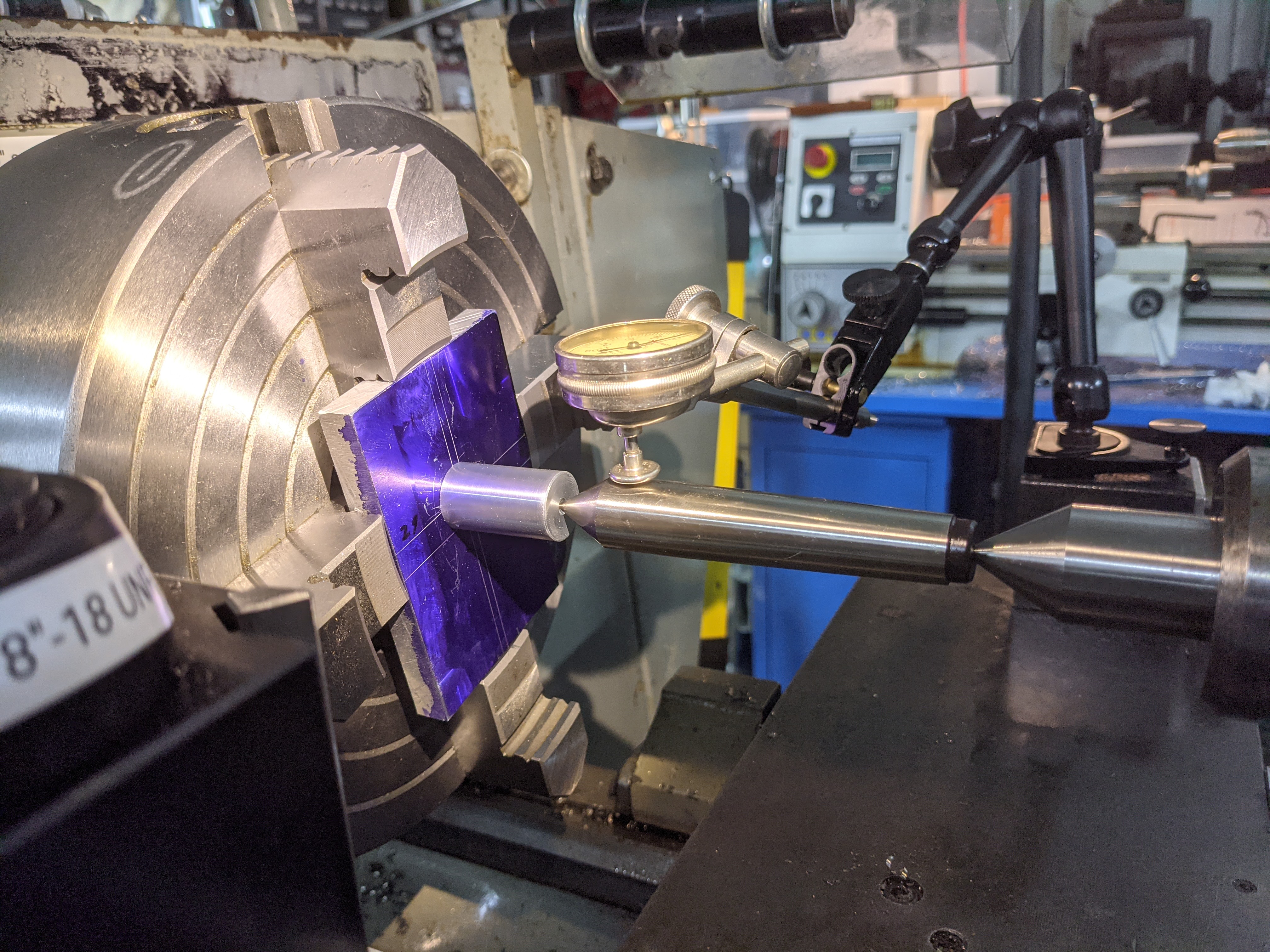
So the idea here is to go semi-precision and use a punch mark on the workpiece. The goal is to center that punchmark (on the lathe in these examples) using some device, whether improvised or commercial. One very simple style of solution involves using a solid rod which has male and female centers at its ends.
Here's the exquisitely simple solution used by Quinn Dunki (aka Blondihacks) which is what got me started. She just used an ordinary dead center, supported between the punch mark and another center held in the tailstock. You put an indicator on this, and adjust the workpiece until it runs as true as you have the patience for.
Here's this setup, reproduced on my lathe. (Dunki uses a dial indicator, which works just fine. I prefer using a dial test indicator, as test indicators - initially non-dial - were the tools designed originally for tasks such as this.)
Dunki's video illustrating (inter alia) this technique is entitled "Stupid Four-Jaw Chuck Tricks" from September 13, 2019. See:
This method has the simple elegance characteristic of old shop tricks, and indeed it is one. I don't know its origin (and indeed it is the sort of thing which was probably done for many decades before anyone wrote it down). I have traced it back to at least 1917, though.
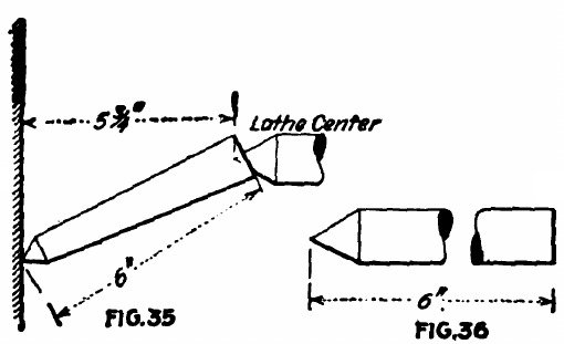
In an article on gagemaking in American Machinist, while discussing many other methods of centering, Charles Albert Macready mentions this method of using a solid "pointer". His pointer isn't literally a lathe dead center, but it possesses the characteristics of one as it is used here: a solid bar with a male center on one end and a female center on the other:
(The image above links to a PDF extract of the entire article.)
Macready mentions a risk in this method (he is assuming that the work is held on a faceplate, not in a four-jaw chuck):
... even with the greatest care when rapping the work to the true center of the lathe, the chances are considerable of forcing the sharp end of the pointer into the work and shifting the center punch mark. (p. 663).
Macready, C. A. "Elements of Gagemaking - II." American Machinist. Vol. 47, No. 16 (October 18, 1917): 661-663.
This is online on Google Books and at The Hathi Trust in scans from several university copies. The Googe Books ID of the scan of the Ohio State University copy is g-09AQAAMAAJ.
A brief illustrated item in the October, 1963 number of Popular Mechanics (Vol. 120, No. 4, p. 183) entitled 'Use Lathe Center as "Wobbler"' shows the use of a lathe dead center (and a Starrett No. 196 indicator) to locate a "center-punched position."
"Centering Indicator." Popular Mechanics. Vol. 120, No. 4 (Oct. 1963): 183.
This is online on Google Books (but in copyright and not downloadable); Google Books ID: CeMDAAAAMBAJ.
Since some of you may track this down, a terminological note is in order. The device (the dead center in this use) is called a "wobbler." This term is natural enough, and indeed terms like it (and "wriggler," etc.) were common for this kind of thing. Take care, though, to distinguish it from the instrument known as a "wiggler," which is sometimes used for centering but which operates according to entirely different principles.
This is the earliest reference I have found so far for using/repurposing an actual lathe dead center in this way.
In his (first) Machinist's Bedside Reader, Guy Lautard describes and draws a simple solid device of this form. He calls it a "wobbler" (as did the Popular Mechanics article of 1963, q.v.) and constructs it using a gramophone needle secured via threadlocker for its female center. He also calls it "well known."
Additionally, he illustrates a "flanged center" which can be placed in a drill chuck. If you already have a drill chuck mounted in the tailstock, you can chuck this center into it rather than taking the time to remove the drill chuck and replace it with a dead center.
It is interesting to note that he says that he has seen drawings of "spring-loaded telescoping" versions of this device, but he feels that "this is an unnecessary elaboration."
Gramophone needles are available as third-party accessories for all of the major streaming audio services.
Lautard, Guy. The Machinist's Bedside Reader. West Vancouver, BC, Canada: [By the author], 1986. ISBN: 0-9690980-2-2.
The next step is pretty obvious: deal with Macready's concerns by making this device spring-loaded.
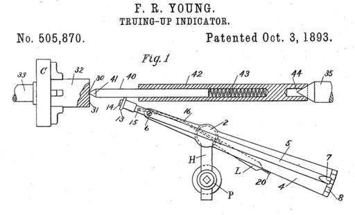
Frank R. Young, of Hartford, Connecticut, filed a patent in 1893 which was, primarily, for an improvement in the mechanism of a test indicator. 1 However, in his first Figure and, explicitly, in his fourth patent claim he describes what he calls a "centering-bar":
4. In an indicator of the class specified, the combination with the indicator-pointer and ... the centering-bar, comprising two bars longitudinally movable the one upon the other and having an intermediate spring, and pointed at one end for engaging the center of a piece of work, and constructed at the other end with a socket adapted to fit the dead-center of the lathe.
(The image above links to a PDF of the entire patent.)
Young does not actually claim the "centering-bar" as an invention in itself. He only claims its use in conjunction with his indicator. It is entirely possible, therefore, that the "centering-bar" predates his patent.
I am unaware of any commercially produced test indicator which contains the features of Young's patent.
Young, Frank R. "Truing-Up Indicator." US Patent No. 505,870. Filed January 12, 1893 as application serial no. 458,129. Issued October 3, 1893. Not assigned.
(This is also an illustration of the difficulty of trade names. Try searching ebay for "Bath Indicator." You get rubber ducks with thermometers.)
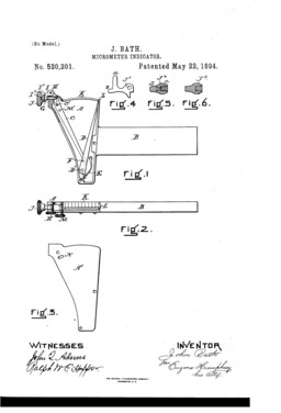
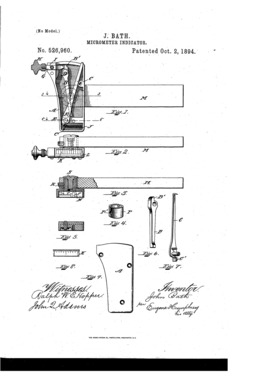
In 1893, John Bath (of Hyde Park, Massachusetts) filed a US patent later issued as No. 520,201 for what he called a "Micrometer-Indicator." It was not a micrometer in the sense that this term is used today, but rather was an indicator using a plunger tip and a double-lever internal mechanism which displayed its results upon a graduated linear scale. In 1894 he filed a second patent which merely added a pivot to the mounting mechanism of the indicator.
(Externally, a Bath Indicator looks a bit like the Brown & Sharpe 738, but I believe that they are different.)
US patent 520,201. Filed 1893-06-10 as application serial no. 477,157. Issued 1894-05-22 to John Bath. Not assigned.
US patent 526,960. Filed 1894-05-02 as application serial no. 509,789. Issued 1894-10-02 to John Bath. Not assigned.
Bath's patents do not say anything about using this indicator with a center locating device, but neither do they exclude it. He says that an indicator is "a tool known among machinists" and his indicator is simply an improved version to be used as any indicator might be used.
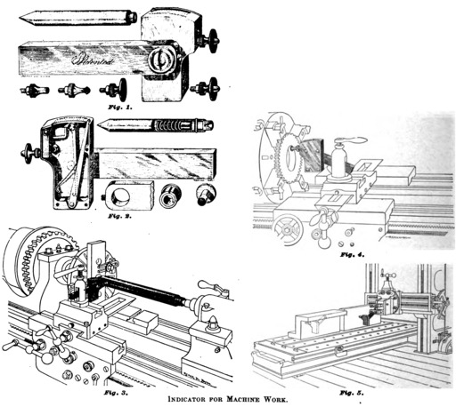
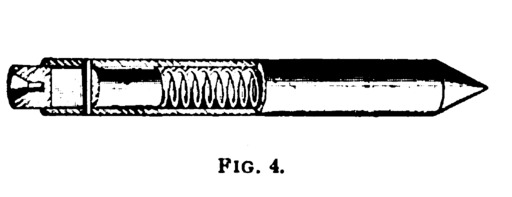
However, the earliest trade notes announcing this device show it in use with a spring-loaded "spindle with conical point" which is "furnished with the indicator." Here it is shown in 1895 in American Machinist:
"An Indicator for Machine Work." American Machinist. Vol. 18 (1895-08-08): 624.
This has been digitized by Google from the Ohio State University copy. ID: y6SRgXHq_LkC.
The Bath indicator was marketed commercially. Here, for example, is a listing for it in a 1902 English catalogue of American tools (showing the spring-loaded "spindle," but not, unfortunately, the cut-away view of this spindle):
(Click on either of the images above for a PDF of the full-page catalogue listing.)
American Tools. [Catalogue] London: Buck & Hickman, Ltd., 1902.
Scanned from an 1989 reprint of this catalogue by the Mid-West Tool Collectors' Association. Public domain.
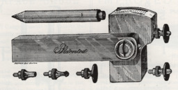
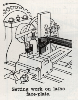
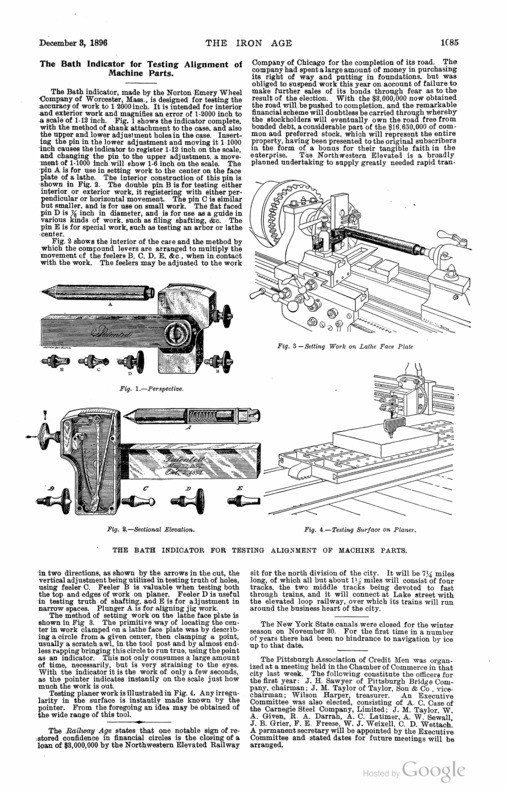
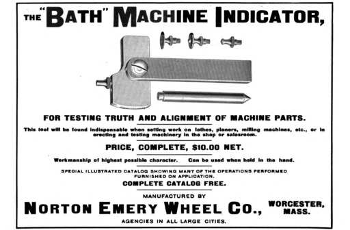
The 1895 trade note in American Machinist says that Bath is making this indicator himself, and the 1902 Buck & Hickman catalogue says nothing to the contrary. But an 1896 trade note in The Iron Age (a well established periodical oriented toward the hardware trades) says that it is "made by the Norton Emory [sic] Wheel Company."
"The Bath Indicator for Testing Alignment of Machine Parts." [trade note] The Iron Age. Vol. 58 (December 3, 1896): 1085.
Digitized by Google from the University of Michigan copy. ID: hwFeMtT9WkEC
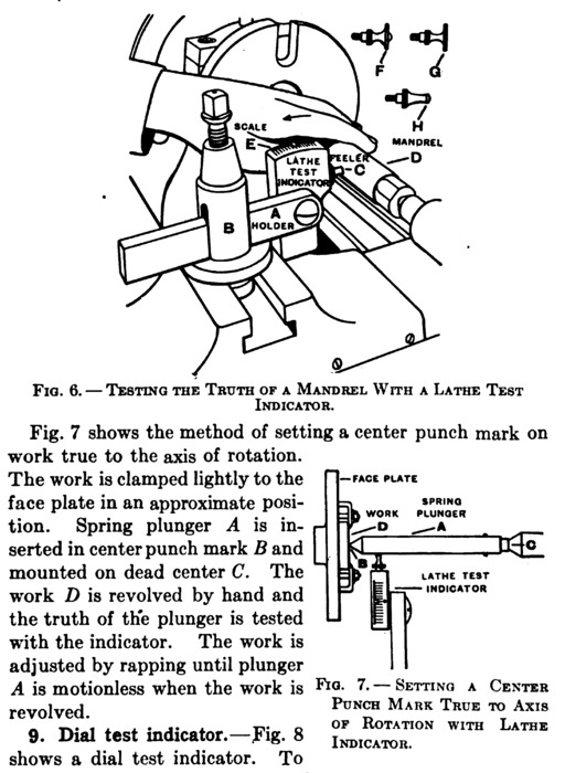
By 1901, this device was well known enough to appear in a textbook:
(The image above links to a PDF-format extract of the relevant sections of this book. These contain a good description of the use of this device.)
International Correspondence School. Shop and Foundry Practice. Vol. 3. Scranton, PA: The Colliery Engineer Co., 1901.
The International Correspondence School began as the Colliery Engineer Co. (and still exists). It prepared is lesson material in short pamphlets which frequently were later collected and reissued as books (here under the Colliery Engineer imprint, later under the International Textbook Company imprint). In this case, the individual paper is entitled "General Hints on Shop Practice." The sectioning and pagination of this particular volume is particularly confusing (and probably incorrect in the original), so citing a page number is not useful. This volume has been digitized by Google several times. The image above is from the version from the Harvard University copy. Google ID: ceIOAAAAYAAJ
Finally (for now) here's an ad from 1905 by Norton for the Bath Indicator:
American Machinist. Vol. 28, part 2 (December 28, 1905): 79.
This volume has been digitized by Google from the University of Michigan copy and is probably available via Google if only you could find it. It is more easily located via The Hathi Trust. Hathi ID: mdp.39015080284477
I can get a bit obsessive about test indicators, so I'll stop with this one for now. The takeaway is that by 1895 or 1896 you could purchase a commercially manufactured spring-loaded centering device for use with your test indicator and its use was described in commercial texts indended for elementary instruction.
In an 1895 letter to the editor of American Machinist, Walter Gribben describes the use of a solid "rod pointed at one end and drilled at the other" in conjunction with a dial test indicator of his own design. He does not illustrate this rod and does not draw any special attention to this method (which suggests that it is widely known).
Gribben, Walter. "Lathe Indicator." [letter to the editor in] American Machinist. Vol. 18 (1895-08-15): 647.
Digitized by Google from an Ohio State University copy. Google ID: y6SRgXHq_LkC
Gribben's article was republished in:
English Mechanic and World of Science, Vol. 62, Whole No. 1589 (1895-09-06): 58.
Digitized by Google from a University of California copy. Google ID: NkdCAQAAMAAJ
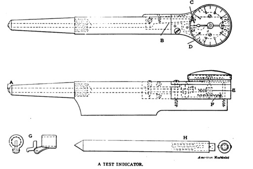
As was the case with the Bath Indicator, this is just a spring-loaded center described as an auxiliary for use with a new style of indicator. The indicator (in this case a plunger-driven dial test indicator) is the inventor's main focus. The centering device is 'H' in the figure below (click on it for a PDF extract of the entire trade note):
Hamer, C. "A Test Indiator." American Machinist. Vol. 27 (1904-01-21): 89.
This volume has been digitized by Google from the Stanford University copy. Google ID: 9K9LAQAAIAAJ
I am unaware of any evidence that Hamer's indicator was produced commercially.
A month later in 1904 the pseudonymous "I. N. Dicator" wrote to American Machinist with a proposal for another plunger-actuated dial test indicator which could be used with a spring-loaded centering device.
I. N. Dicator. [pseud.] "A Test Indicator and Holder." American Machinist. Vol. 27 (1904-02-04): 154.
This volume has been digitized by Google from the Stanford University copy. Google ID: 9K9LAQAAIAAJ
At least two textbooks by Robert H. Smith show this method. (He illustrates what is clearly a Bath Indicator, but does not name it.) It is shown in the second edition (1912) of his Text-Book of the Principles of Macine Work (it's probably in the 1910 first edition, but I don't have access to that). The same material appears in his Text-Book of Advanced Machine Work (shown below from the 1915 third edition; again, this probably appeared in earlier editions):
(This image links to PDF format extract of the relevant pages from the 1915 volume.)
Smith, Robert H. Text-Book of the Principles of Machine Work. Second Edition. Boston: Industrial Education Book Company, 1912. (Earlier edition in 1910.)
Digitized by Google from a University of California copy. ID: 4KAQAAIAAJ
Smith, Robert H. Text-Book of Advanced Machine Work. Third Edition. Boston: Industrial Education Book Company, 1915. (Earlier editions in 1910 and 1912.)
Digitized by Google from the University of Wisconsin copy. ID: dcpKAAAAMAAJ
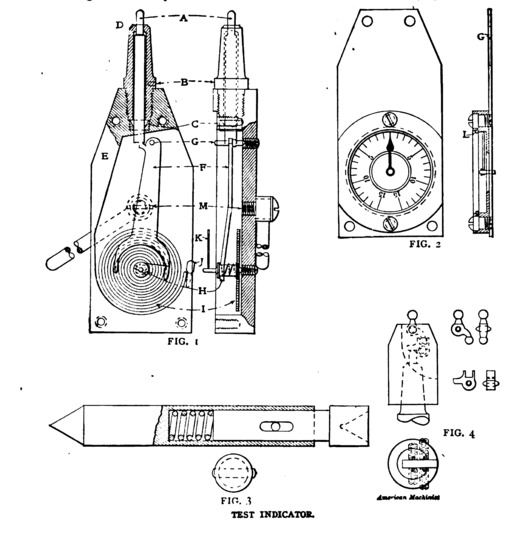
Earlier we saw C. A. Macready's comments on using a solid rod in his 1917 American Machinist article. He also discusses the use of spring-loaded rods (he calls them "pointers") and, interestingly, offers some comments on their issues and construction.
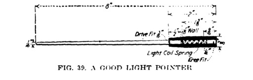
He first illustrates a simple spring-loaded pointer of the style seen often here (his Fig. 39; see the PDF of the article for this illustration). Then he says:
"In Fig. 38 is illustrated a pointer that has a spring to compensate for the variation in length due to moving the work toward the center of the lathe. On the face of it, it looks all right; and it is all right if made like Fig. 39, which brings us to the cause of errors that are in all indicator pointers and that should as far as possible be eliminated when the pointer is used in delicate punch marks - that is, the inertia of the pointer.
"The pointer is forced to move, not slowly, but with violent jumps when the work is rapped toward the center. [He is writing of work held on a faceplate, but you can operate a 4-jaw chuck roughly as well.] The pointer should therefore be as light as is practicabl, to offset as much as possible the stress upon the side of the center punch mark due to the inertia of the pointer. This stress becomes a blow the intensity of which varies with the force of the rap required to move the work, and the resistance of the indicator needle to be moved. In Fig. 39 is shown a good light pointer, which will offer the least resistance to a quick movement of the work from a state of rest." (pp. 663-664)
Unfortunately, I do not have an original of this volume of American Machinist and the only available digital version, by Google, is of very poor quality. Here, in the best version presently available to me, is his Fig. 39:
(The image above links to a PDF extract of the entire article. The article indicates that this material was to be a part of a then forthcoming book by Macready, but I have not been able to locate such a book.)
Macready, C. A. "Elements of Gagemaking - II." American Machinist. Vol. 47, No. 16 (October 18, 1917): 661-663.
This is online on Google Books and at The Hathi Trust in scans from several university copies. The Googe Books ID of the scan of the Ohio State University copy is g-09AQAAMAAJ.
I have never seen a commercial version of a light pointer such as the one Macready shows, but, then again, you're a toolmaker: you can make your tools.
In the 21st century there has emerged an unfortunate tendency to call the spring-loaded device under discussion here a "pump center." (Even more confusingly, some discussions call a spring-loaded tapping guide a "pump center.") This is unfortunate for two reasons. First, this term was never used to describe it during the period in which it was a regular workshop tool. Second, since at least the late 19th century there has been a well-established lathe accessory called a "pump center." Calling something else a "pump center" just introduces needless confusion.
I'll note the instances where this kind of device is now being called a "pump center" as they come up. For a discussion of why this is not a good idea and what a pump center really is, see the section What To Call These Devices?" below.
In a project posting on the website of the Home Metal Shop Club of southwestern Texas, George Carlson describes an provides measured drawings for a spring-loaded device of this type. See "Shop Made Pump Center" at http://www.homemetalshopclub.org/projects/pmpcntr/pmpcntr.html (the posting itself doesn't have a date, but if you trace its history through The Wayback Machine its earliest is on 2002-06-19.
At present, this posting is also the earliest instance I have found of this device being called a "pump center." For a discussion of why this is not a good idea and what a pump center really is, see the section What To Call These Devices?" below.
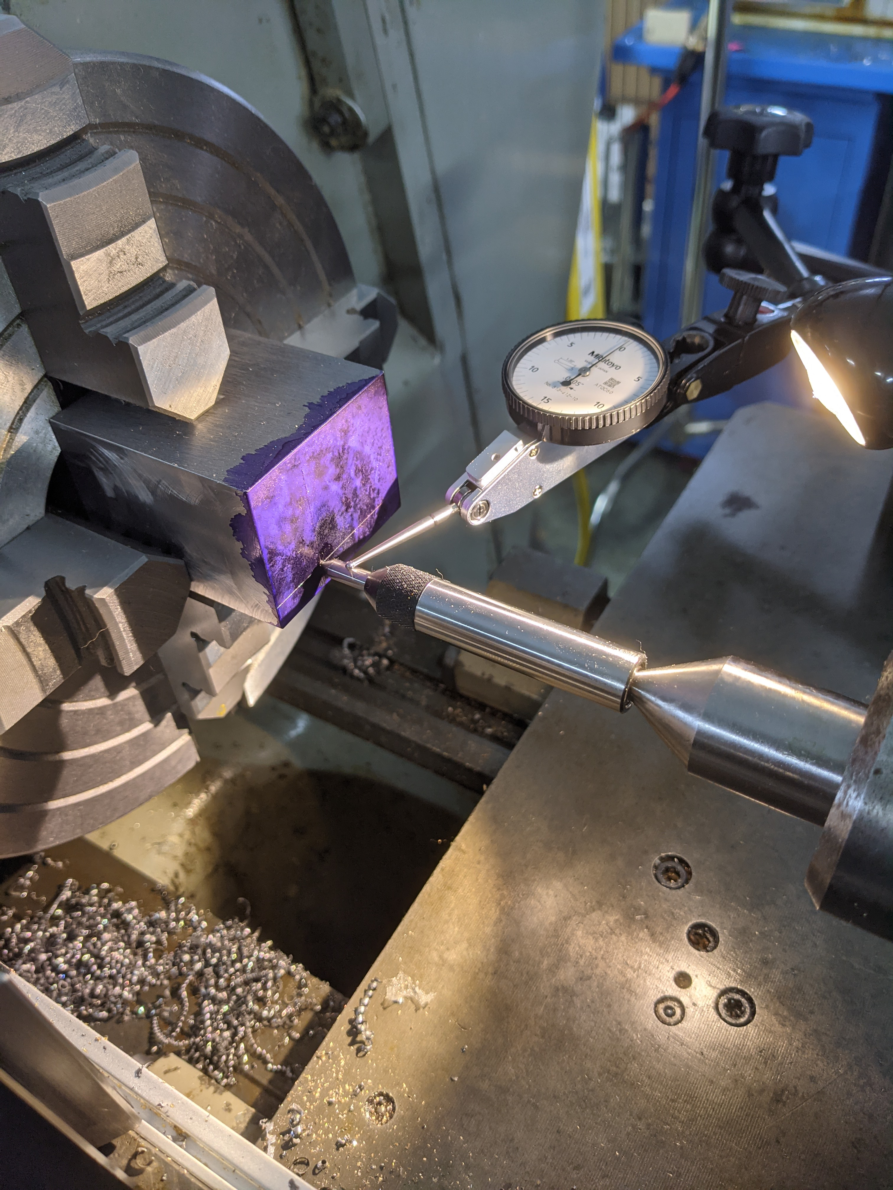
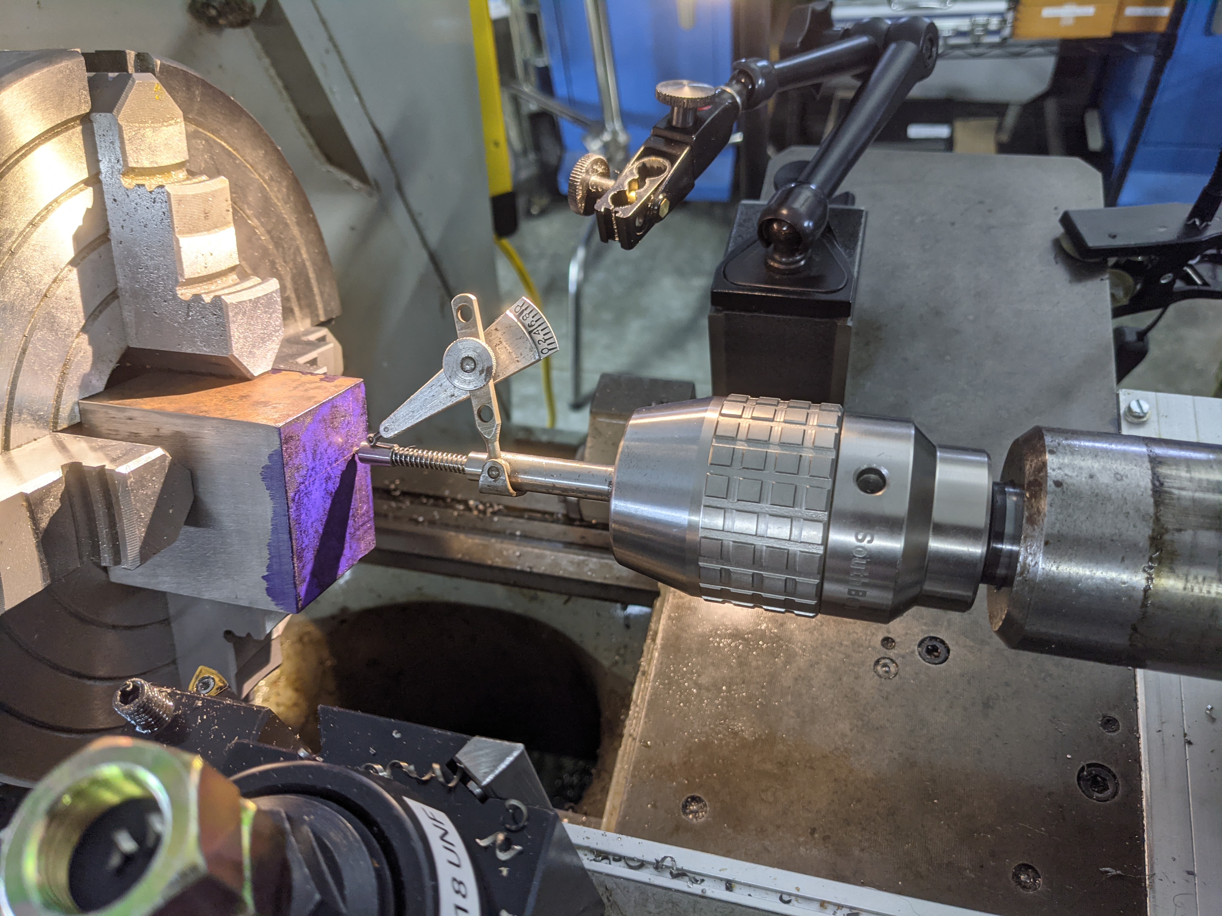
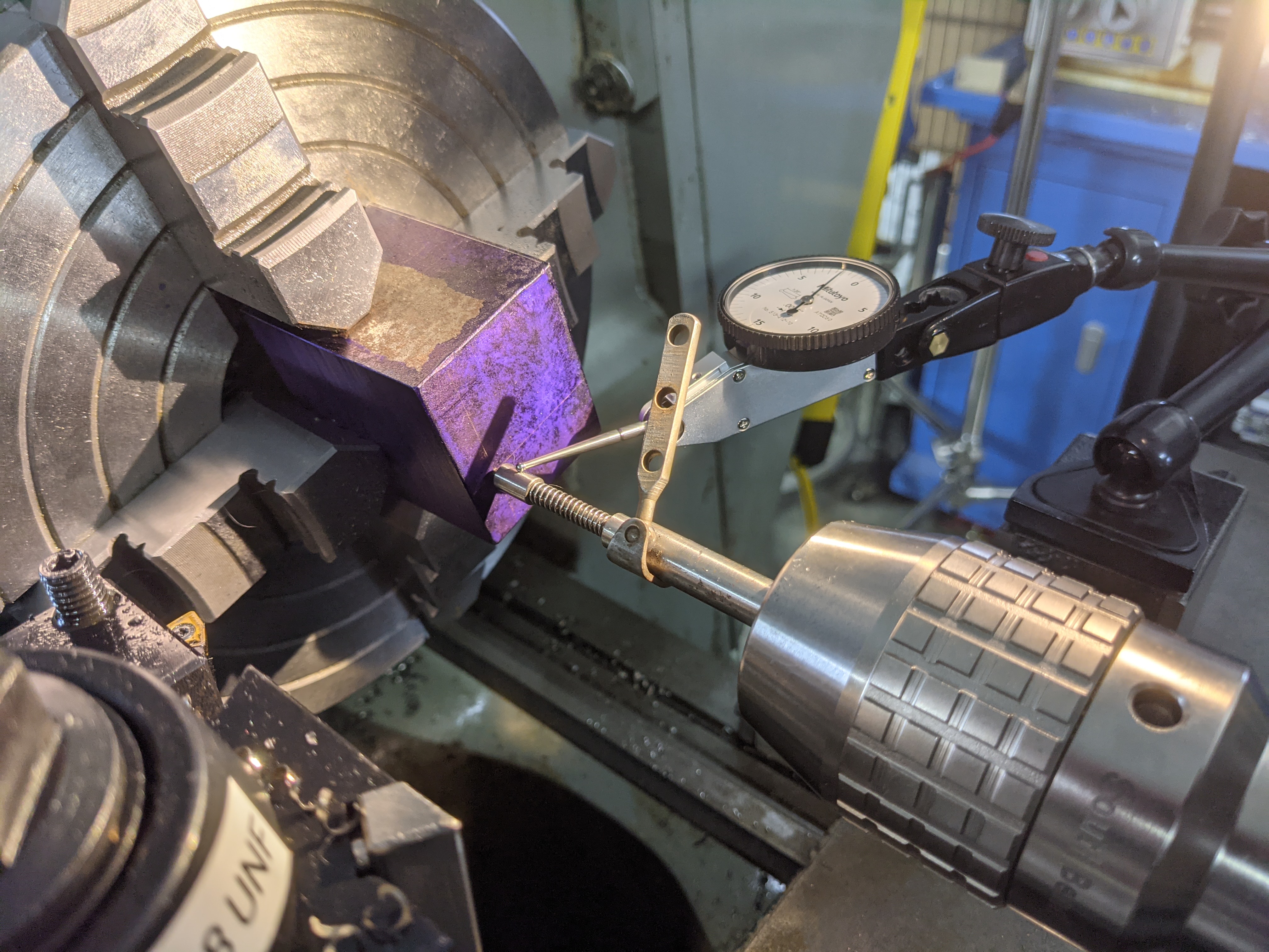
This is the solution that I hit upon when I was working on the project which triggered all of this research. Of course, it turns out that it is not a new idea.
So here's a photo of a commercially manufactured spring-loaded tapping guide repurposed for centering a punch mark on the lathe. For more on this, including photos of tapping guides and their intended use, see the section "First View of the Rabbit Hole" in the "Instagram vs. the Ents" Workshop Update.
However, the idea of repurposing a spring-loaded tapping guide dates to at least 2010 (for the use of shop-made tapping guides). The idea of repurposing a commercially produced tapping guide dates to at least 2012. For both of these, see the 2010-2012 thread "Pump Center" from the "Home Model Engine Machinist" forum, discussed below.
Of course, 2012 is a pretty recent date as I write this in 2021. In comparison to all of the 19th century references here, it's practically tomorrow. I'll bet that this specific idea is much older.
This thread on the Home Model Engine Machinist's forum ran from 2007 to 2010 (with some later additions) and illustrated several interesting variations on the spring-loaded version of this device (as a dedicated centering device, as a dedicated tapping guide, and as a combination of the two - with some lack of fine distinction between the spheres of application). The thread began on Nov. 4, 2007 and had the title "Pump Center." It is online at: https://www.homemodelenginemachinist.com/threads/pump-center.471/ (although not all of the images display all of the time; it is not archived on The Wayback Machine). It was quite a productive thread, with many contributions worthy of note.
(However, see the section What To Call These Devices?" below, for a discussion of the issues involved in calling this kind of device a "pump center.")
Forum user "Tin Falcon" started the thread, with a drawing of a spring-loaded device similar to those shown above. He called it a "Pump Center." His image is very small, but the drawing in it is comprehensible. There is no suggestion in his posting that this device has any application to tapping.
Then on July 20, 2010, user "TroyO" referenced a similar - but not actually equivalent - device from the ProjectsInMetal.com website (now offline). It turns out that this device, while called a "Spring Center" by its designer, is actually a spring-loaded tapping guide. Moreover, without modification (the addition of a female center on one end) it can only be used as a tapping guide, not as a centering device. For more on it, and a link to an archived version of the ProjectsInMetal.com page, see the discussion about it in the "Instagram vs. the Ents" Workshop Update .
On 2010-07-20, user "mklotz" suggested both using a solid rod (as discussed earlier) or a flexible rod mounted in the tailstock (see Burton's 1970 proposal in the section A Flexible Rod in the Tailstock," below).
On 2010-07-20, user "wheeltapper" / Roy Grafton presented, photographically, a lovely spring-loaded device with a male center on the front end and a female on the back. He called it a "pump centre" and described it as useful both for centering and as a tapping guide (albeit only with a T-handle style of tap handle). Curiously, this post is dated 2010 but his photographs are all watermarked 2011.
At present, Grafton's device is the earliest reference I can find to a (shop made) spring-loaded tapping guide being used also as a punch mark centering device (or vice versa, or as a combination tool, depending on how you want to look at it).
On 2010-07-21, Tyler Youngblood posted photos of the one he had made using the ProjectsInMetal.com plans, but unfortunately these photographs have disappeared.
On the same day, user "winklmj" posted photographs of a functionally similar device. It might have tapered components, or not (it's a bit hard to tell from the angles of the photos). Fortunately, these photos are still online (or were when I last looked; the forum's photo hosting is via a third-party site which sometimes rate-limits access).
A day later, user "SAM in LA" posted a photograph of one that he had made based on the ProjectsInMetal.com plans. He did note, though, that he had centerdrilled a female center in the back end.
In a late addition to this thread, on August 17, 2012, user "Omnimill" added two links to an item in the online catalog of the well-known UK supplier of model engineering tools, Chronos Ltd. Of course, in the fluid world of the Internet this link is now dead, as their catalog has been reorgnized. But if you track down an archived version of this via "The Wayback Machine" at The Internet Archive, you find that this item is simply an ordinary spring-loaded tapping guide as pictured on my lathe above. See:
https://web.archive.org/web/20110607142218/http://www.chronos.ltd.uk/acatalog/threading_accessories.html
https://web.archive.org/web/20091104055540/http://www.chronos.ltd.uk/acatalog/info_318221.html
At present, Omnimill's posting is the earliest reference I can find to the repurposing of a commercially manufactured spring-loaded tapping guide as a punch mark centering device.
(This entry is here mostly because I'm trying to keep a log of the early 21st century uses of "pump center" for a spring-loaded punchmark centering device.)
In a long and detailed posting on "How To Center Work In A 4 Jaw Chuck" on the Hobby-Machinist forum on 2015-11-03, user "HMF" briefly describes the use of a spring-loaded device of the kind discussed here. He calls it a "PUMP CENTER."
This device could also, reasonably, be considered as a Self-Contained Center Indicator (q.v.) if you take the "Center Tester" and its associated Test Indicator as a single unit. But the Ideal Center Tester was sold as a separate unit and could be used with any indicator, so I'm putting it in a separate category here.
This was a commercially manufactured product. I doubt that it ever achieved wide sales (speaking from experience, it is harder to use than some of the simpler solutions), but I was able to pick one up on ebay for a reasonable price when I began this research.
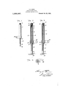
It was patented by Harry O. Brion (filed 1920, issued 1921). The patent was assigned to Alfred G. Cash, of Rochester, NY. We know that Cash was affiliated with the Ideal Tool Company because on March 19, 1915 he signed an agreement, as a representative of the company, with the International Association of Machinists for the use of the Union label on its products. (See the Machinist's Monthly Journal Vol. 27, No. 5 (May, 1915): 397.) Here is Brion's patent:
US patent 1,395,087. Filed 1920-04-12 as application serial no. 373,103. Issued 1921-10-25 to Harry O. Brion. Assigned to Alfred G. Cash.
Trade notes for the Ideal Center Tester appeared in 1921 in American Machinist (Vol. 54 (1921-04-07): 623) and Machinery (Vol. 27 (May 1921): 902. In both cases, the device was being sold by Johnson & Miller, of New York, as agents.
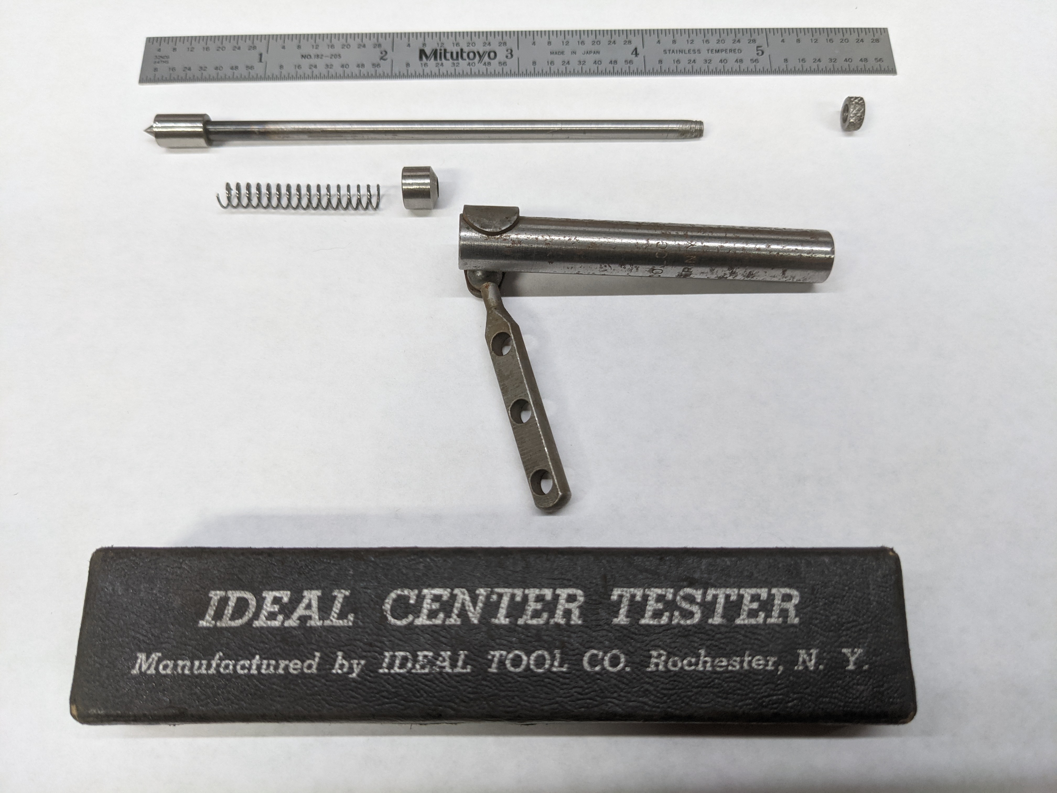
The Ideal Center Tester is a spring-loaded plunger that is held rigidly in either a tailstock chuck on the lathe or in the spindle of a milling machine. (My sense is that it was really intended more for milling machine use.) It has a male center on its working end. Its other distinctive feature is a collar with a bevel which tends, under spring pressure, to align the movable part of the device with the fixed part. It also has an attachment bar for a test indicator. (Naturally, the Ideal Tool Co. would have preferred you to use an Ideal Test Indicator, but any test or dial test indicator will work.) Here is an Ideal Center Tester, disassembled, with its original box:
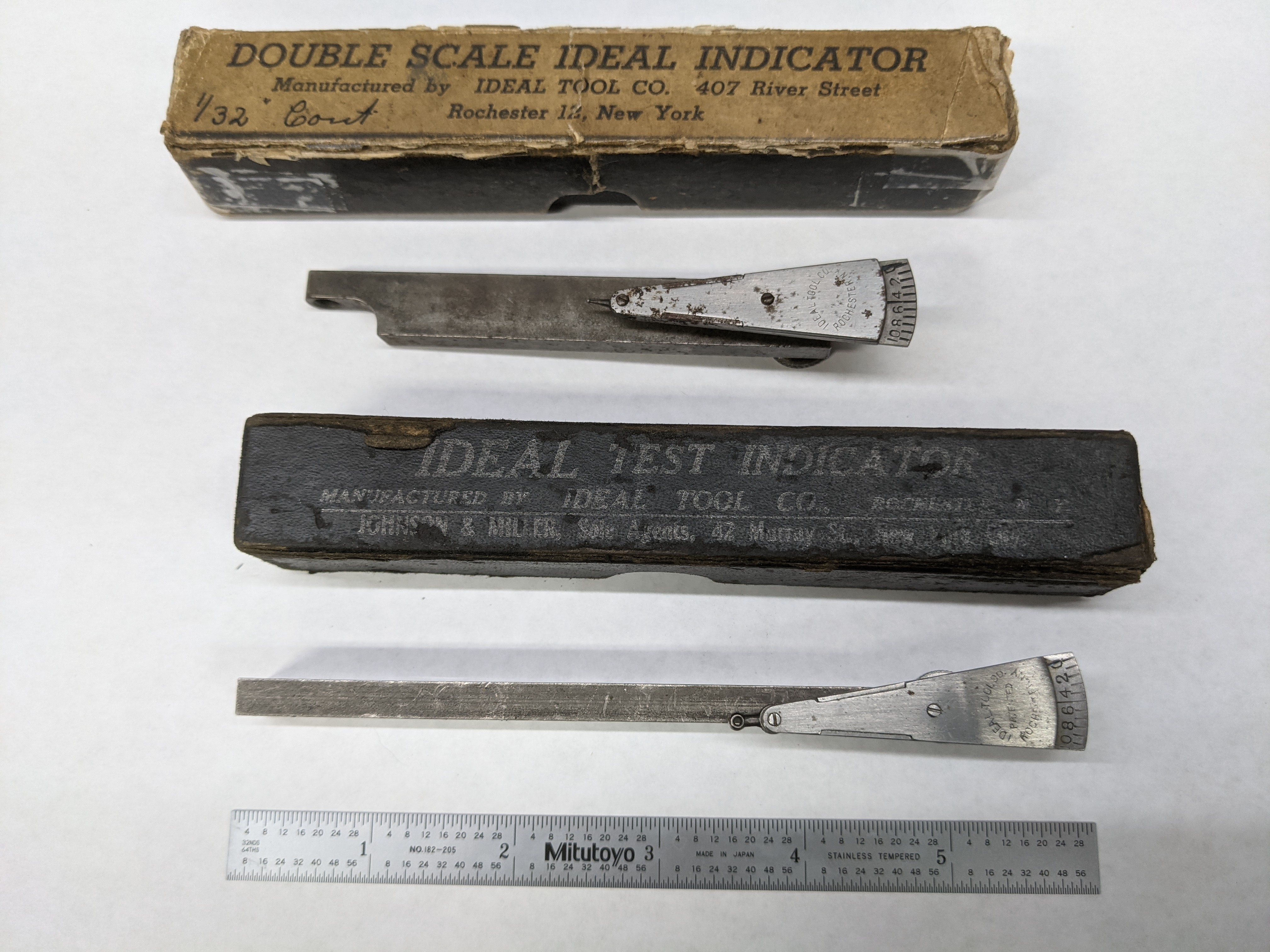
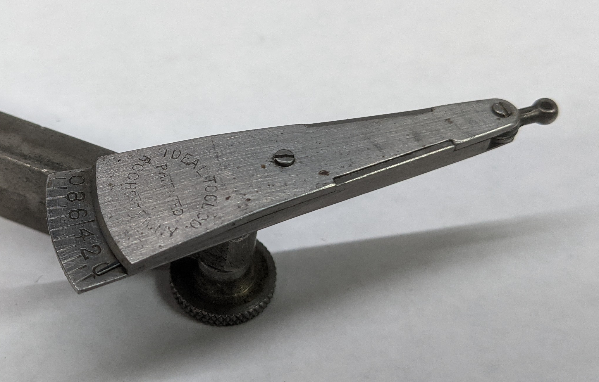
Here are a couple of Ideal Test Indicators:
(A cautionary note: Ideal Test Indicators are simple, but remarkably difficult to reassemble.)
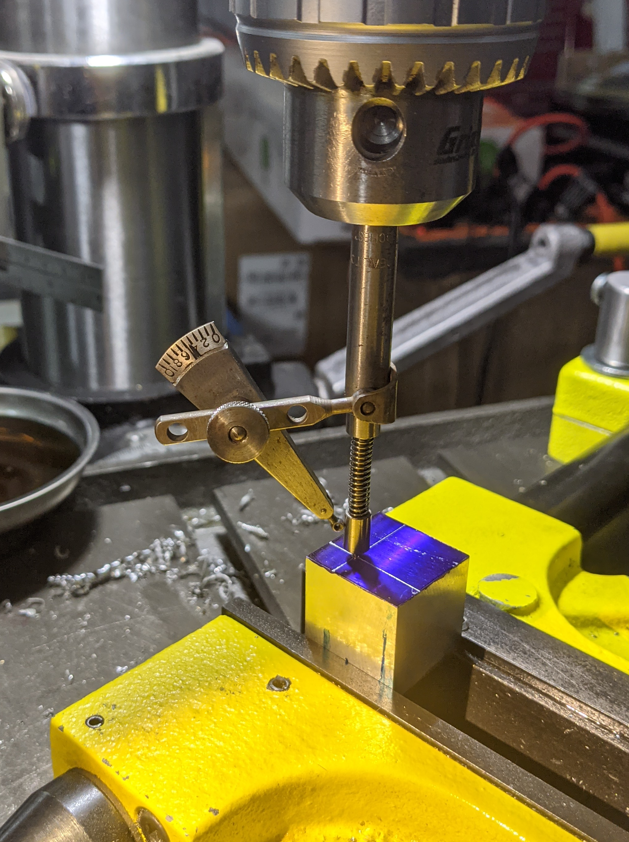
Here's the whole setup, assembled and shown locating a hole on the drill press. (Ideal made two styles of Test Indicators, one with a scale on a single side only and one with a scale on both sides. I'm using the latter here because it makes the indicator easier to read as it is rotated.)
Here is the combination of the Ideal Center Tester and Ideal Test Indicator shown in use on the lathe (below left) and the Tester alone shown in use with a modern dial test indicator (below right):
The Ideal Center Tester is a clever idea, but in practice I found it finicky to use. The mechanism of the beveled ring under spring pressure did not move smoothly. Any of the spring-loaded plungers against a tailstock center would be easier to use.
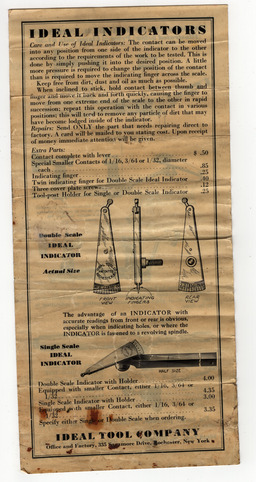
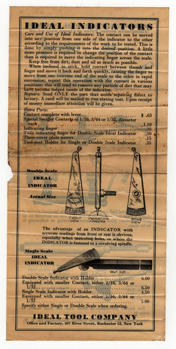
Because I don't think that it has been reprinted before, here is the insert in the Ideal boxes which advertises and shows the uses of their single and double scale Indicators, their indicator Holding Clamp, and the Ideal Center Tester (with PDFs of scans from two different copies and links to the original 1200 dpi scans, because that's how I do things).
(These are relatively large files, at around 120 Megabytes each.)
Rudy Kouhoupt, now deceased but well known to hobby machinists through his writing (and presentations at meetings), published the design of a "Center Finder" (as he called it) which is very much like the Ideal Center Tester. The only substantive difference is that while the Ideal had a beveled ring which tended to return the plunger to center, Kouhoupt's has a plain ring which does not.
Kouhoupt, Rudy. "Make a Center Finder" in The Shop Wisdom of Rudy Kouhoupt, Volume 2. Traverse City, MI: The Village Press, 1996.
The chapters of this book were published initially in The Home Shop Machinist. I'm not sure when this particular article first appeared, but it would have been between 1989 and 1995.
John Moran (GadgetBuilder) has posted a design for a device based on Kouhoupt's. The primary difference is that in Moran's version the spring is safely shrouded by the tailstock-held body of the device. The earliest archived version of this posting, in The Wayback Machine, is from 2004-11-16. It is still online (at the time of writing) at: https://www.gadgetbuilder.com/CenterFinder.html
The archived versions of this article reveal an interesting twist on the issue of the new use of the term "pump center" for devices of this type. In the earliest versions, Moran simply says that Kouhoupt "... had made a tool which included a spring ..." (and in fact Kouhoupt does not refer to this device as a "pump center." He simply calls it a "center finder.") But at some point after 2009-06-04 but before 2010-02-04 this wording changed to "... had made a tool (a 'pump center') which included a spring ..." This is useful information in tracing the spread of this term through the model engineering community. (For more on this issue, see the section What To Call These Devices?" below.
This solution is a distinctly novel approach which I find brilliant in its simplicity.
In a 1970 article in Popular Mechanics on the use of several kinds of indicators, Walter E. Burton suggests using a flexible shaft with a pointed end, the pointed end engaged with the punch mark and the other end held in a tailstock chuck. Use the indicator of your choice with this setup (his illustration shows a dial indiator in use).
Burton, Walter E. "You Can Improve Your Lathe Work with Indicators." Popular Mechanics. Vol. 133, No. 5 (May 1970): 177.
This is online on Google Books (but in copyright and not downloadable); Google Books ID: 8dcDAAAAMBAJ
In 2010 in a thread on the Home Model Engine Machinist forum, forum user "mklotz" proposed this same idea very briefly.
The methods describe so far allow you to center a punch mark to an arbitrary degree of precision using what amounts to little more than two sharp sticks. To the enterprising American machinist, this situation represents not a solution but rather a problem to be solved by the invention of a special-purpose tool.
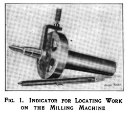
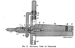
This is a device on entirely different principles which relies upon feel (and the entry of pins into holes) rather than a visual assessment. It seems to have been developed primarily for use on the milling machine, although its use on the lathe is entertained. It isn't an "indicator" in any sense that this word is used now, but that's what its inventor called it.
The device consists of something like a lathe faceplate or a disk held in the spindle of the mill. This disk has four holes in its periphery, at 90 degree intervals. From its center a pointer is supsended (by a spring) in a kind of a ball joint. An arm extends from this pointer up to the periphery of the disk, where it is equipped with a removable pin. To use the device, put the pointer in a punch mark on the workpiece to be centered. Then adjust its location until the pin can enter easily into all four of the holes on the periphery of the disk. This can only happen when the pointer is square with the disk, and therefore in-line with the spindle of the machine. Nothing needs to rotate during this operation, and if you align the four test holes with the X and Y axes of the mill the adjustment should be straightforward. It's a bit complex to describe, but really very clever.
Murdock, George J. "Locating Indicator for the Miller." American Machinist. Vol. 33 (1910-08-25): 337-338.
Digitized by Google from the University of Michigan copy. Google ID: pmEfAQAAMAAJ
Clearly at least one was made, but I do not know if this device was ever manufactured commercially.
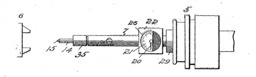
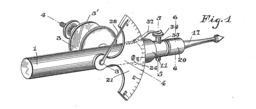
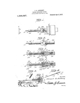
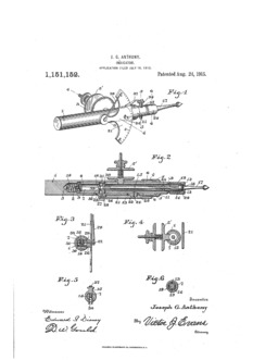
The next pair of devices, from Joseph G. Anthony in 1912 and 1913, are self-contained tailstock-mounted center indicators with graduated scales. They're interesting not only in their own rights but also because as single-scale 2-D indicating devices they are on the path of intellectual development which leads to the Haimer (brand) and Renishaw (brand) 3-D locating probes used on CNC machining centers today.
US patent 1,058,027. "Center-Indicating Device." Filed 1912-03-27 as application serial no. 686,604. Issued 1913-04-08 to Joseph G. Anthony. Not assigned.
US patent 1,151,152. "Indicator." Filed 1913-07-18 as application serial no. 779,854. Issued 1915-08-24 to Joseph G. Anthony. Not assigned.
This device, described in the "Letters on Practical Subjects" column of Machinery, is conceptually very much like Murdock's Locating "Indicator" of 1910 (q.v.) Construction details aside, the primary difference between the two is that while Murdock relied upon the fitting of pins into holes Ljungquist employs readings of a dial indicator.
Ljungquist, Hugo. "Centering Device." [In "Letters on Practical Subjects" column] Machinery. Vol. 31 (June 1925): 811-812.
Digitized by Google from the Stanford University copy. Google ID: MqlFAQAAIAAJ
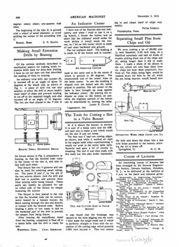
In 1910, James K. Cloud encountered a novel problem as he was trying to keep up-to-date in his methods, and he proposed an interesting solution. He wrote it up, very briefly, in a letter to the editor of American Machinist. Here's his letter. But if you don't have a background both in the use of toolmaker's buttons and in the history of dial test indicators the letter can be confusing (particularly since his drawing is out of context, his figures face backwards, and few people now employ the style of indicator he was using).
Cloud, James K. "An Indicator Center." American Machinist. Vol. 33 (1910-11-03): 838.
Digitized by Goodle from the University of Michigan copy. Google ID: pmEfAQAAMAAJ
Here, set up on my lathe, is the problem that Cloud faced. He was using a toolmaker's button to locate a feature. Traditionally, this would be done with a (non-dial) test indicator. Today (not that many people use toolmaker's buttons) you would use a modern lever-style dial test indicator. No problem. But Cloud was trying to use the Starrett No. 196 Dial Test Indicator, which had been introduced in 1903. Although this indicator is still in production, it represents an early and fairly unusual digression in the history of dial test indicators. Unlike most later DTIs, its probe is a plunger (not a lever) and the probe is located on the back of the indicator. This means that it is hard to get in to certain locations, which is just the problem Cloud faced: "I found the button was so short that the indicator would strike the work before it would touch the button." Indeed, you cannot use a Starrett No. 196 with a toolmaker's button.
I liked the ingenuity of Cloud's solution, and thought that the best way to explain it would be simply to make one. Cloud made his out of tool steel, hardened and ground. I just ran mine up in aluminum in a few minutes on my other full-size lathe (a Precision Matthews PM1228VF-LB, which is really just a Sieg SC10 (Shanghai Sieg Machinery Co., Ltd.) in blue paint). It is just a cover that fits snugly over a toolmaker's button and has a female center in its closed end.
So you have your toolmaker's button on your workpiece and you slip Cloud's cover over it:
Then set it up with an "indicator center" (as Cloud called it; I'm using a dead center here). The Starrett No. 196 now works just fine.
Of course, a couple of months later another correspondent to American Machinist, Walter G. Groocock, took issue with Cloud's solution. He pointed out that by moving the point of measurement beyond the end of the button it magnified any error which might be present in a button which leaned slightly. Groocock's solution was to use a lever attachment (equivalent to, say, a Starrett No. 671 Universal Attachment) to convert a dial indicator into a dial test indictator.
Groocock, Walter G. "The Dial Test Indicator for Setting Work on the Lathe." American Machinist. Vol. 34 (1911-01-26): 173.
But Groocock didn't quite address Cloud's situation. He describes the use of a lever attachment with an ordinary dial indicator. Such a lever attachment will not fit the Starrett No. 196. Instead, you would need the Starrett 196F Hole Attachment. That attachment had been added by 1911, but it was not a part of the No. 196 set as it was introduced in 1903.
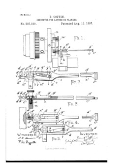
In 1896, Frank Coffin filed a patent for a non-dial test indicator. In one application of it, he shows it used to center a punch mark. However, I cannot figure out how this could work as there is no means described for aligning the pivot-point of the indicator with the axis of the lathe.
US patent 587,930. Filed 1895-11-20 as application serial no. 612,874. Issued 1897-08-10 to Frank Coffin. Not assigned.
The devices under discussion here have never had a single accepted name, even within the various subtypes.
The solid version has been called a:
The spring-loaded version held against a tailstock center has been called a:
The spring-loaded version held rigidly in the tailstock has been called a:
The version consisting of a flexible rod presents the easiest case. It has been called a:
More specialized instruments have been named:
It is probably also worth noting that the style of device most commonly sold commercially for this purpose, which I'm generically calling a (Lever) Center Indicator (q.v.) was called several other things:
All of this would seem to indicate (pun intended, of course) that you might as well go ahead and call it whatever you wish. There are at least two caveats, though.
First, it is probably best to avoid terms such as "wobbler" and "wriggler," and to avoid the term "wiggler" entirely. The reason for this is that there is today an edge-finding and centering device known universally as a "wiggler" that operates on entirely different principles. It isn't used as much as it once was, but you can still buy them new. However, the operation of the wiggler is often misunderstood, especially with regard to its optional pointed tip and center-locating abilities. Adding anything at all to the confusion surrounding the wiggler seems a disservice to the community.
Second, in these first years of the 21st century, it seems increasingly common to call the spring-loaded version (held against a tailstock center) a "pump center." This has been done by:
When I began writing this Workshop Update, I was all set to argue that this was not a good choice of names for the simple reason that there is a lathe accessory which has been around since the 18th century and which is still in production today which has since the 19th century (at least) been known consistently in the literature as a "pump center." The lathe pump center is entirely unrelated to the center-indicating devices under discussion here. (For a discussion of what a lathe pump center really is, see What Is a Pump Center? below.) As old as the devices under discussion here might be, the real lathe pump center was there first. Using a well established name for a lathe accessory to identify some entirely different lathe accessory does not seem like a good idea.
I still think that this is the case, and would suggest strongly that "pump center" is not a good name for this device. But I have found one instance in the 20th century literature where the spring-loaded, tailstock-center-supported version of this device was in fact called a "pump center." This seems to have been an isolated case, so it would be easy simply to dismiss it. The problem is that the person who used this term was an authority of considerable stature: J. Robert Moore.
The primary reference comes in his book Precision Hole Location (Bridgeport, CT: The Moore Special Tool Co., 1946): 24. 2 If you are unfamiliar with American machine tool history, J. Robert Moore developed the jig borer (The Swiss developed it independently, as well.) His son, Wayne R. Moore, wrote The Foundations of Mechanical Accuracy (1970), which remains the basic work on this subject. Yes, you do need these books. (As an aside, all of the research I have done suggests that the Moore Special Tool Company also invented the machinist's 1-2-3 block. That's a journey down a different rabbit hole, though.)
So Moore wasn't just any guy writing about precision hole location. He was, arguably, the leading authority in the world in this area. The fact that he used this term in print, twice, lends it considerable weight.
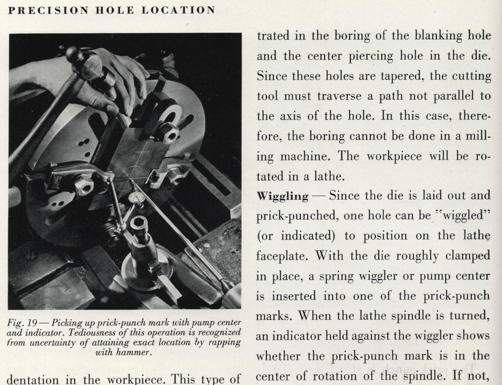
But we should look at the context in which he used it. Unlike the many writers to American Machinist or Machinery at the turn of the 20th century, Moore wasn't writing to advocate this device. He was reviewing earlier methods, and was not entirely sympathetic to them. The chapter in which this reference appears is entitled "They Got Holes In Somehow." The caption to its first illustration concludes: "... But at what price!" Here's an extract showing the operation (although its "tediousness ... is recognized...") and his use of the term "pump center":
The fact that Moore used this term is evidence that some machinists in the first half of the 20th century did employ it, but it is scarcely a recommendation. Moore would have preferred that we never use this method at all.
A pump center is a device most commonly associated with the watchmaker's lathe, although there is some evidence that its use was known in general machine shop work.
It is found in both modern (meaning late 19th century) forms of the watchmaker's lathe, the "Webster-Whitcomb" (WW) form as commonly found in the US or the less rigid "Geneva" form derived from the WW style and more common in Europe. Lathes of this latter style are still in commercial production in China and are sold worldwide - with optional pump centers. (Just to do it, I checked ebay as I wrote this. There were four listings for Geneva-style watchmaker's lathe faceplates supplied complete with pump centers, new from China.) However (and rather surprisingly to me) the origins of the pump center origins date back to some of the earlier forms of the watchmaker's lathe. In particular, it can be seen on the "universal mandrel" in the 18th century and had roots before that in the watchmaker's "uprighting tool." The name "pump center" (in English) for this device is used consistently in the literature from at least 1881 through at least 1985.
For reference, in case you might be unfamiliar with watchmakers' lathes, the image below left is of a Rivett brand WW style lathe. The image below right is a Geneva-style lathe (branded the "Victoria lathe" by its importer). Both have through-holes in their spindles and take nominally identical collets (8mm WW style collets in this case). The WW style of lathe has a relatively complex history (for which see Ward L. Goodrich's The Watchmakers' Lathe (Chicago, IL: Hazlitt & Walker, 1903)). In simple terms it was developed in the USA in the late 19th century and it introduced the through-hole spindle to the watchmakers' lathe and the concept of the collet to the lathe in general. While the Geneva style is lighter and less rigid, it is acutally a slightly later development which adapted these American innovations to Swiss preferences. WW collet compatible lathes are still being made, but the WW lathe in the classic style shown here is no longer manufactured. You can still buy a Geneva-style lathe new from China on ebay - with a wide range of accessories including a faceplate with a pump center. It's really very tempting.
(The Rivett illustration is from the circa 1904 catalog "Wide Awake" Catalogue of Tools and Materials for Watchmakers, Clockmakers, Jewelers and Opticians. (Oldham, Lancs., UK: Hirst Bros. & Co., Ltd.): 81. The Geneva illustration is from the 1923 catalog of Henry Paulson & Co., a materials dealer in Chicago: Paulson's National Reference Book of Materials and Supplies for Watchmakers, Jewelers and Opticians. (p. 151)
A pump center is a part of the faceplate attachment for the watchmaker's lathe. 3 It is in fact intended to center points on work held on the faceplate, but it does so by a method entirely different from the spring-loaded tailstock-supported device discussed earlier. A pump center is just a rod which fits snugly within the spindle bore and which has a pointed end which projects through the center of the faceplate. To use it, you push it out through the faceplate, center the feature of interest on it (typically a hole) and then withdraw it to allow free work on this feature.
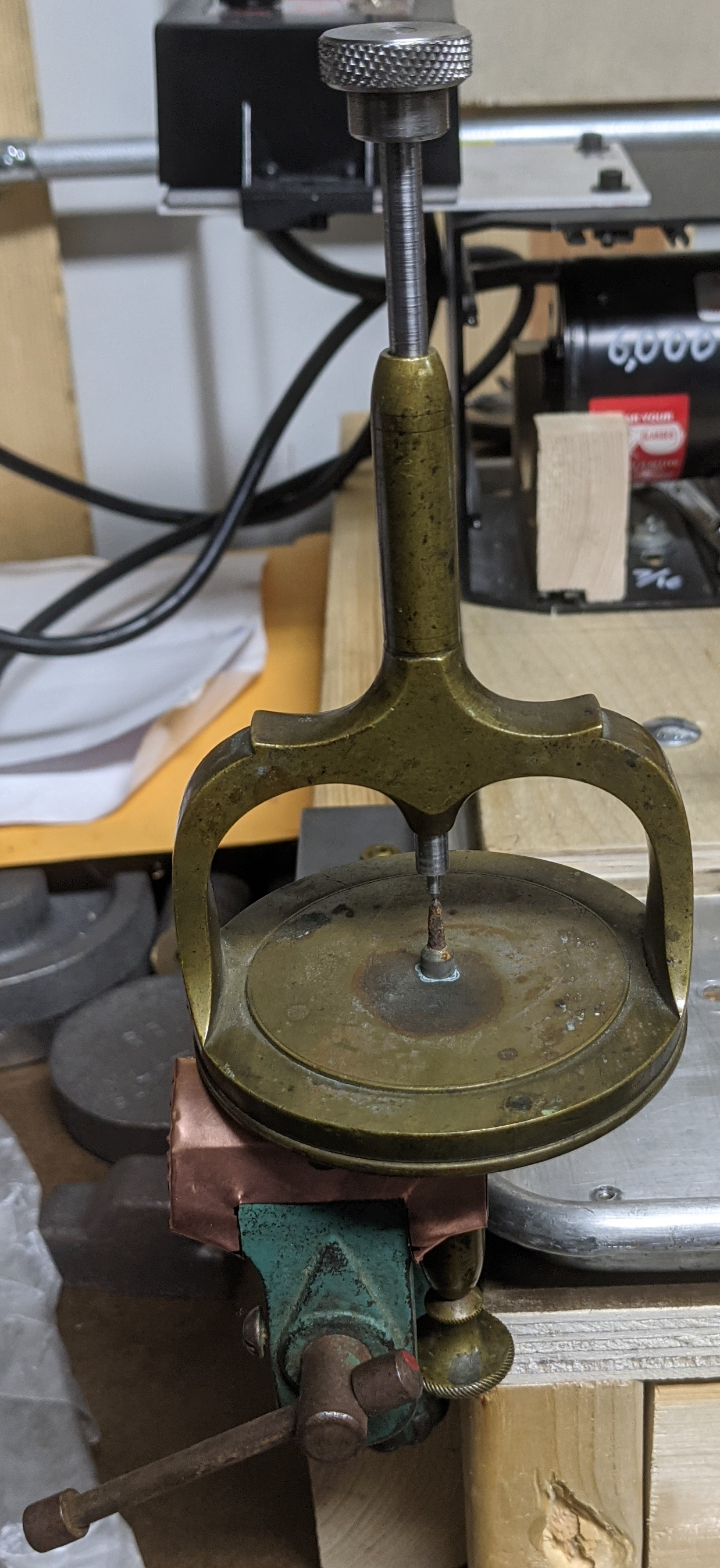
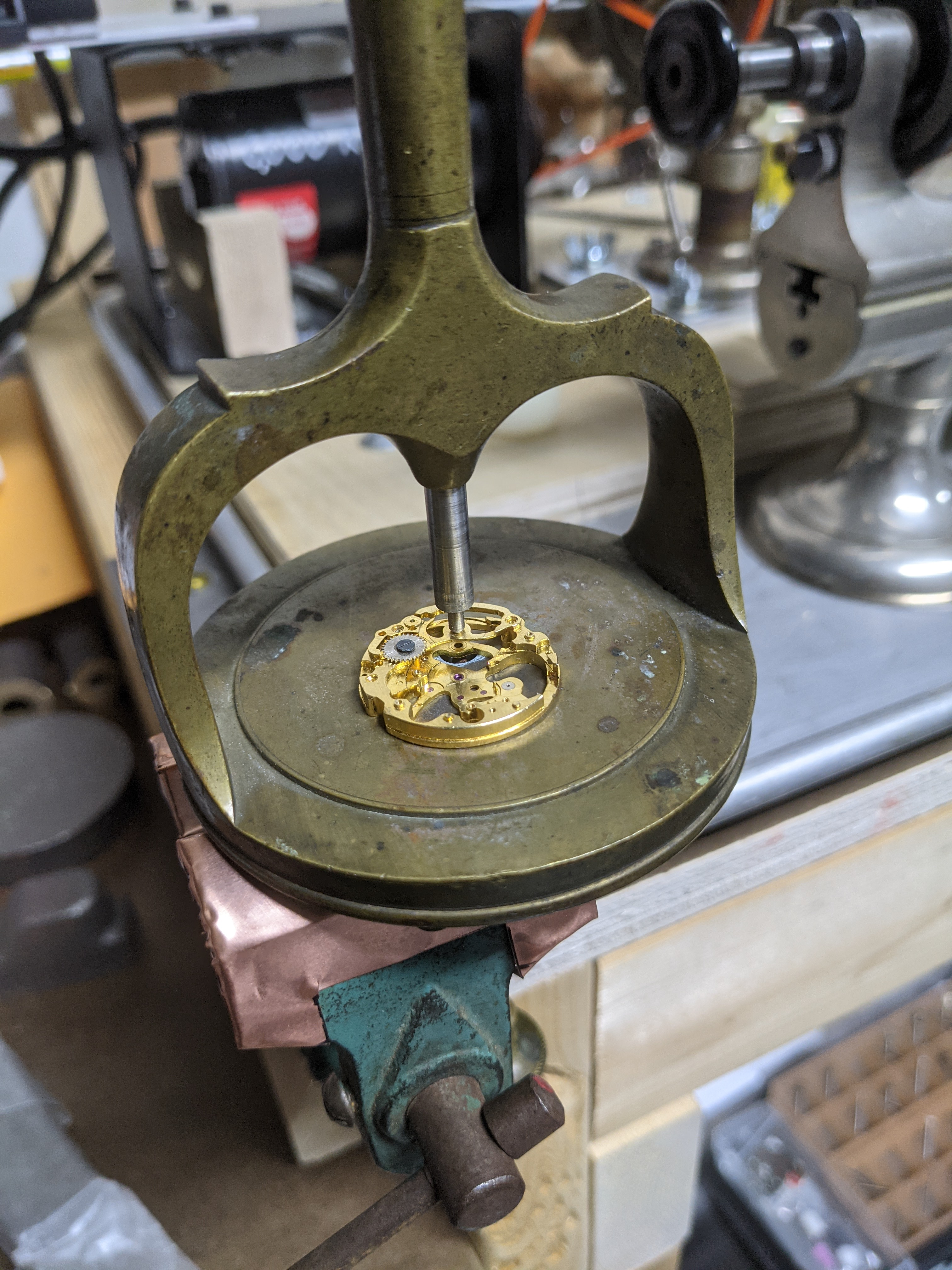
To illustrate this, here is my current primary watchmaker's lathe set up with a faceplate, pump center, and a skeletonized watchplate as a workpiece. (You might want to click on the photo to zoom in. I should have put a sheet of paper behind the lathe to help distinguish it, visually, from the drive countershaft behind it.)
Details for lathe nerds (and if you aren't a lathe nerd, well, why are you here?): The lathe itself is an 8mm WW style lathe (thus with a 50mm center height, or 100 mm swing in American terms). It was made in Germany (probably in the 1930s) for the Chicago-based Paulson materials house and was branded "Paulson" by them. As shown it equipped with a collet-holding micrometer tailstock which might be original to it and a tip-over T-rest which is not. It's being driven by a Sherline variable speed DC motor mounted inside a lovely big aluminum extrusion which was originally the shell of an external hard disk array. See - computers do have their uses! The antique countershaft is nameless. The other countershaft has nothing to do with this setup. You can also see a watchmakers' "turns" in the background.
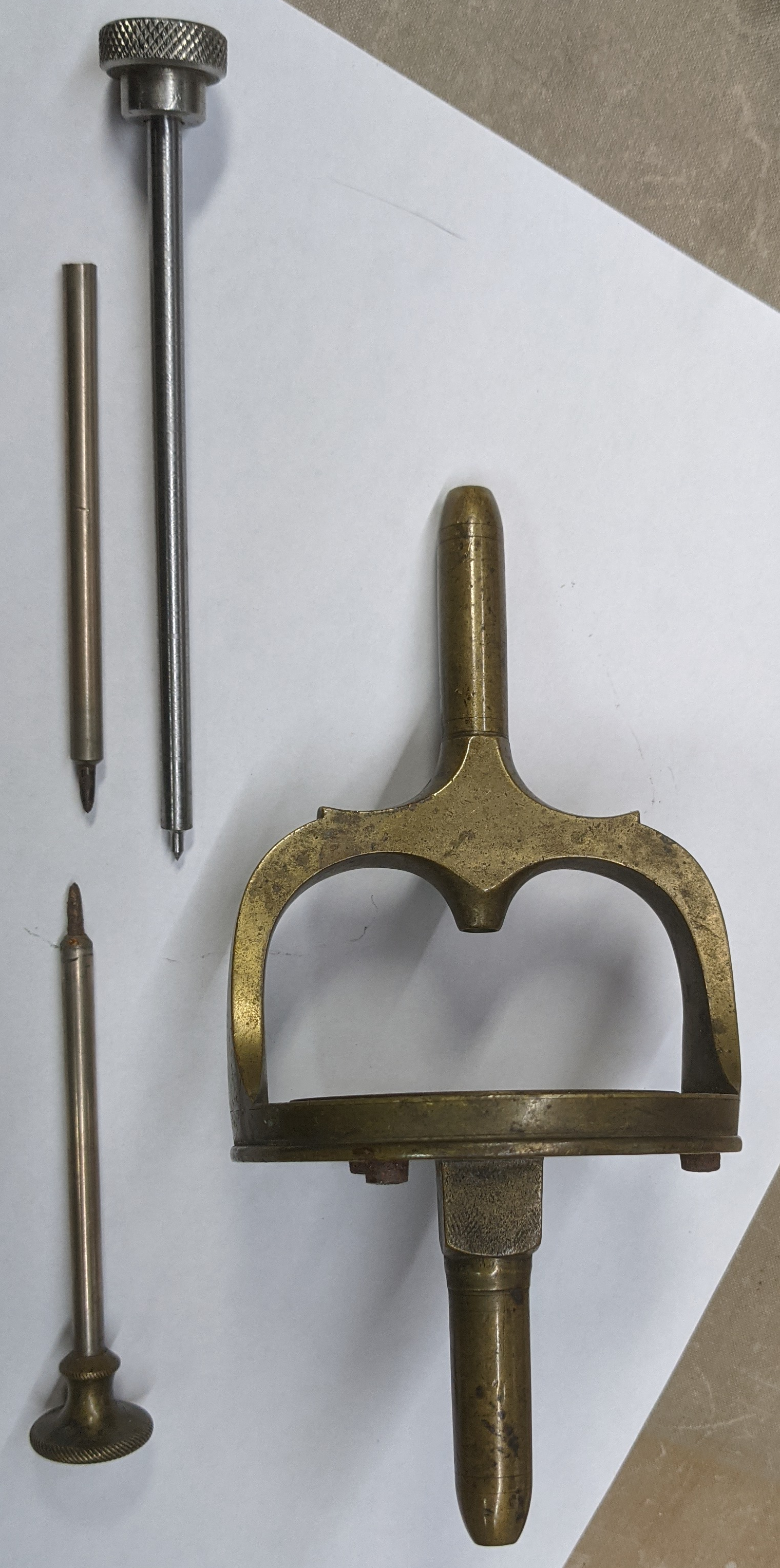
Also - and relevant to this discussion - the pump center as I received it had only its pointy bit. (That's a technical term: pointy bit.) The shaft and handle, which screwed on, had gone missing long before I bought the unit. So as shown I've just assembled a crude but functional substitute using dial indicator extension rods with the same thread (M2.5x0.45mm). 4 An original (or a properly fixed) pump center would have an additional little knob at the far left of the headstock.
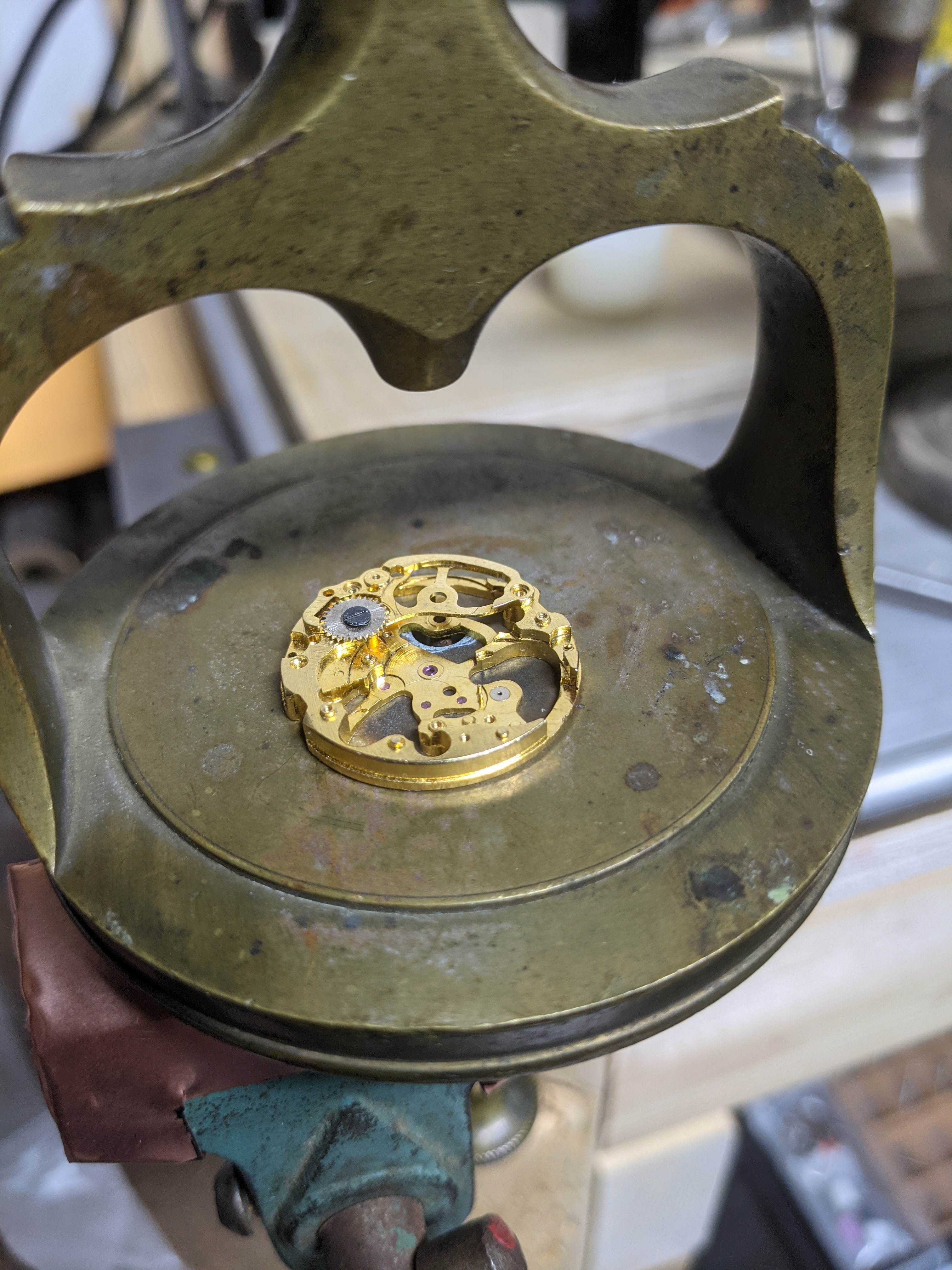
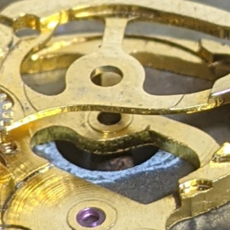
The faceplate of a "modern" watchmaker's lathe is generally equipped with three clamps which allow the work to be held above the actual round plate. In the photo below left you can see the bottom plate of a "Tongji" Chinese Standard Watch movement, skeletonized, held in these clamps. One of the holes in it has been centered using the pump center from the headstock behind it. Below right is a closeup of this hole - you can see the conical center poking through it.
Here's the same setup viewed from the side, first (left) with the pump center engaging the hole to be centered and second (right) with the pump center withdrawn so that some operation might be done on or concentric with this hole.
Some pump centers were equipped with springs to retract them automatically from the work. (DeCarle mentions this in The Watchmaker's and Model Engineer's Lathe, and Hirst (1904) says of the Rivett Universal Head and Universal Face Plate: "The pump centre is fitted with a light spring..." Other pump centers did not. It does not appear that the pump center with my faceplate ever had a spring; it relies on a very snug fit in the collet bore to keep it back away from the work once retracted.
For a slightly clearer view of the parts of a faceplate and pump center here is the one advertised for the Kampe (brand) lathe in Paulson's 1923 catalog. It is not equipped with a spring. It is equipped with a bushing on the pump center's handle/rod (or whatever you wish to call it). This bushing is neither present nor really necessary in mine.
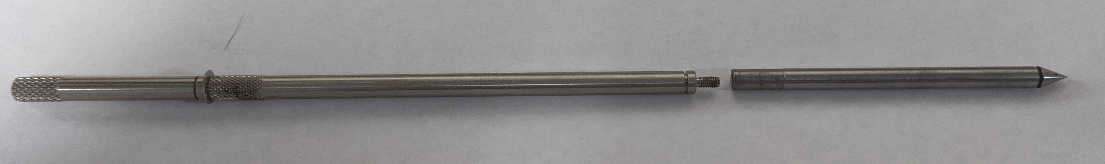
Here is the pump center from my lathe as shown above. More precisely, the pointy bit on the right is all that survives of the original pump center. The rod on the left is just two lengths of M2.5x0.45 dial indicator extension rod screwed together (with a completely unnecessary washer stuck between them that I thought would be useful for added grip).
That's what a pump center really is. Your lathe doesn't even have to have a tailstock to use one.
But there's no way I could stop here. There are two questions which come to mind immediately: how long have we called this thing (in English) a "pump center" and what are its origins as a device (regardless of what it might have been called centuries ago)? I'll cover the first of these questions here and the second in the next section.
TO DO: Saunier. Goodrich. DeCarle. Derbyshire catalog
The earliest description in English that I have found of the predecessor of the pump center is in Thomas Martin's The Circle of the Mechanical Arts (1813). This is a general encyclopedia of mechanics, not a specialist's treatment, but it is nonetheless very detailed. Martin describes this device in its earliest form, incorporated into a "Universal Mandrel" (see the next section for the evolution of the pump center in the context of the evolution of the lathe headstock). He calls it a "centre-pin" (p. 576 and Fig. 9 of the plate "Clock Work.")
The earliest description in any language that I have found (again, so far) which calls this device a pump center is Claudius Saunier's Guide-manuel de l'horloger (1870). In it, he calls this device "une pompe à centrer." (In his section describing the "Tour Universel" shown on his Plate VI, Figure 2, which is what would be called in English a "Universal Mandrel," he describes it the arbor or mandrel itself and says "L'intérieur de l'arbre est muni d'une pompe à centrir,
The Liste 28 of the German manufacturer Wolf, Jahn & Co. (undated, but probably the middle of the first decade of the 20th century) shows on p. 52 both a "Universal-Planscheibe auf extra Spindelstock" (a universal faceplate with its own headstock, or "universal head") and a "Universal-Planscheibe zum Einstecken in den gewöhnlichen Spindelstock" (a universal faceplate to plug into the usual headstock, meaning a collet-mounted faceplate) both of which were supplied with a "Zentrierspitze" (literally a "centering point.") This is arguably a much better name for this device.
(As noted earlier, Saunier in 1870 refers to this device as "une pompe à centrer.")
Use of the term "pump center" in drafting/layout compasses and trammels.
This use is a fairly natural extension of the term, since (a) it doesn't produce any confusion because it isn't being used to identify some other lathe attachment, and (b) the motion of a trammel's "pump center" is linear, just as is the motion of a watchmaker's lathe's pump center (but quite unlike the spring-loaded centering device).
TO DO: Martin 1815 Circle of the Mechanical Arts Plate "Clock WOrk"
1. If you are unfamiliar with the non-dial test indicator, it is basically a calibrated lever (sometimes simple, sometimes compound). It came in many variations and was the predecessor of the now common dial test indicator. The dial indicator, although it can sometimes serve some of the same purposes, has a completely different historical origin and generally a different operating mechanism. (There is, of course, a grey area exemplified by the Starrett No. 196, which is a dial indicator configured as, and marketed as, a dial test indicator. Also, the nomenclature employed by Brown & Sharpe didn't help the cause of clarity at all.)
2. Moore also used this term in a chapter he wrote in 1949, "Jig Boring and Grinding," for the American Society of Tool Engineers' Tool Engineer's Handbook (NY: McGraw-Hill, 1949): 674. This article was later extracted into the book Basic Machining Operations (1951) by what was then the ASTME.
3. It was also possible to purchase a headstock and faceplate combined into a single unit, with a pump center but without the ability to use collets. This was called a "Universal Head" (Goodrich uses this term in The Watchmakers' Lathe (1903) and Rivett called theirs by this name). Such a "Universal Head" provided the best possible faceplate, of course, since the faceplate was attached solidly to the spindle by the factory. However, it could only accomodate faceplate work, so you would also have to purchase a regular headstock for collet work.
4. The Webster-Whitcomb lathe was designed during a more progressive period of American industry (1889) and is of course metric throughout.
The copyright on Moore's 1946 Precision Hole Location was not renewed. It is now in the public domain, as is the extract from it here.
All of the reprinted material reprinted here which has been digitized by Google and/or which is available through The Internet Archive or The Hathi Trust is in the public domain.
The Paulson and the Hirst catalogs from which material is reprinted are in the public domain, as are the extracts reprinted here.
All portions of this document not noted otherwise are Copyright © 2021, 2022 by David M. MacMillan.
Circuitous Root is a Registered Trademark of David M. MacMillan.
This work is licensed under the Creative Commons "Attribution - ShareAlike" license, version 4.0 International. See http://creativecommons.org/licenses/by-sa/4.0/ for its terms.
Presented originally by Circuitous Root®


