It's been a while since I've posted a workshop update. That isn't to say that I haven't been busy in the shop; quite the opposite. But of course it takes a lot longer to write something up than to do it in the first place.
Today most people solve this problem quite readily by posting a photo to Instagram. If I were to do that (which in this case I cannot, since the photo is on my computer and doesn't have the mobile tracking metadata that forms the basis of Instagram's product - remember, if it's commercial and free, then you are the product)... anyway, if I were to, then the photo would be this one:
This is fine, I suppose. A few people who do traditional manual machining might think either "that's clever" or "so what?" But without context, it's pretty meaningless.
The context is the exhausting part. I took that photo two weeks ago. Since then, I've been working pretty steadily on putting it in context. I've finished enough to put some of the context online, but there's a lot left to do (none of which involves working on the projects I should be working on).
I think of this in terms drawn from Tolkien's The Lord of the Rings. You may remember Fangorn, the Ent - one of the shepherds of trees. At one point in the story, two of the hobbits come into his care and, in consequence, stir things up to the point that the Ents hold a gathering, an Entmoot, to discuss whether they should take action against the wizard-gone-wrong Saruman.
Several days into the Entmoot the hobbits begin to wonder why it is taking so long. Fangorn explains it to them in terms which seem to be linguistic, but which are also cultural. It isn't just that it takes a long time to say anything in Old Entish; that much is obvious. It is, Fangorn explains, that they never say anything unless it is worth taking a long time to say.
Instagram is like Saruman: dazzling on the surface, but less profound than he believes himself to be. What we need, instead, is more technical writing in Old Entish.
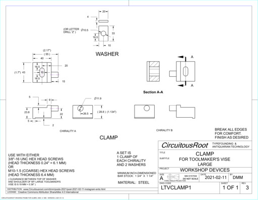
This whole matter came up because of a side project - not even the project I should be working on. Having watched too many Stefan Gotteswinter videos on youtube, I had replaced, some time ago, the regular vise on my G0759 (BF-20 style) small mill with an overgrown toolmaker's vise. But this particular vise does not have a slot around the base for easily clamping it to the table. So I designed some clamps to do this:
BTW, I'll be the first to point out that these clamps, as I made them, look awful. Even hiding the worst of their problems through carefully posed photographs (remember, when you're offsetting a mill in a slot, r = D/2) they're pretty bad. If I were a high school shop teacher in 1955, I'd give them a C- just to let the kid pass. If I were in charge of an apprentice at the Great Western Railway works in Swindon in 1855, things would not go well for the lad. At the same time, these clamps are completely sound and functional. This will prove to be annoying in the future, because they'll be in use on this mill, staring back at me in all of their imperfection, for years to come.
Their design, on the other hand, isn't half bad. So here is the drawing:
And, because I believe in open source hardware, here's a tarball of the CAD model (Alibre Design format, with exports to STEP): clamps-for-large-toolmakers-vise-rev3.tar.gz
This is a well established style of clamp. Most of the dimensions aren't critical. The offset of the "spigot" (cylinder) was designed so that, in combination with the slot, pairs of these clamps could always span to some T-slot regardless of the position of the hole on the vise. The washer is designed to cover the slot on the clamp fully regardless of the hold-down bolt position. Your vise probably will have different dimensions, so redimension as desired.
I can recommend this as an excellent beginner's project for learning how to machine steel (especially on a machine where rigidity is an issue). It has a good mix of simplicity plus features (spigot, deep slot) and the very loose acceptable tolerances provide a margin of safety. I treated it, as well, as an exercise in learing about indexable-insert carbide tooling (which works surprisnigly well, even on this tiny mill - but you can also get into a whole lot of trouble 1 ). It can, further, be satisfying to know that however bad the results one has still reduced the apparent entropy of the world. Here's the block of scrap-bin steel that one of these clamps is made out of:
Remember: the fastest stock removal tool in the shop is the bandsaw.
Each clamp has a short cylindrical portion (it would have been called a "spigot" in the older model engineering literature; I'm not sure if that term persists today). This must be machined as an integral part of the clamp. Drilling a hole and pressing a pin in won't give the necessary rigidity. So how can one make this feature?
There are of course many different ways. As you would expect, my first instinct was not to have my CAD/CAM system generate g-code to control the 5-axis milling center (which I don't have). Old school is more fun: in this case, the four-jaw chuck on the lathe. So here's the feature, apparently done. (I say apparently because after I took this photo I noticed something. If you look closely - you may have to click on the image to get the full-size version - you can see that the flat surface behind the spigot is actually curved or domed. It turns out that the pressures of the operation were enough to push the compound rest back ever so slightly on each pass. Sigh. That's why they put a gib lock on every slide.)
The trick here is that you need to align the workpiece in the 4-jaw so that a punch mark at the desired location is on the centerline of the lathe's spindle. 2
By complete chance, at about this time I happened to watch one of Quinn Dunki's videos on youtube. For those of you not familiar with her work, she writes and engineers under the name "Blondihacks" and is currently producing some of the finest introductory machining instructional videos ever made. (I offer this as a professional opinion. In my career I was a technical writer and did a fair bit of classroom technical instruction. Although my career was in the software industry, I know good instructional material in any field when I see it.) Her work has just the right combination of accessibility and technical accuracy. There are many good youtube machinist's channels (and many bad and at times dangerous ones, too - be careful!) But for a viewer just starting out in machining, you can't do better than Blondihacks. See: https://youtube.com/c/Blondihacks, and also her website ( http://www.blondihacks.com) and Patreon page ( https://www.patreon.com/QuinnDunki).
The video of note here is one entitled "Stupid Four-Jaw Chuck Tricks" from September 13, 2019 ( https://www.youtube.com/watch?v=00dl0DxRYvM). In it, she centers a punch mark on a workpiece in the 4-jaw chuck by using an ordinary dead center between the punch mark and another center in the tailstock. You put an indicator on it, and as you rotate the chuck by hand you can adjust the workpiece so that it is centered. (Dunki uses a dial indicator, which works just fine. I prefer using a dial test indicator, as test indicators - initially non-dial - were the tools designed originally for tasks such as this.)
Here, re-created on my lathe, is the setup:
This method is simple and effective. Its only disadvantage is that you have to adjust the tailstock pressure on the dead center as you get closer to center.
But this solution begs a question: why not make it spring-loaded?
Then it occurred to me that I already had something which would serve this purpose and which was already spring-loaded: a spring-loaded tapping guide. These aren't as well known as they should be, but they're still standard commercially available products.
Here are three spring-loaded tapping guides.
The two on the left are versions of the same style by different makers. In each of them, the tip may be reversed to present either a male center (as shown at the far left) or female center (as shown in the middle), as appropriate for your tapping situation. The device is held together by a socket head cap screw in the base. This will be important to us here.
The tapping guide on the right is of a different style and its tip is not reversible. It also has a plain solid base, so it will not be of use here.
Here is the tapping guide shown at left above in use. You chuck it into your drill press (or mill). Depending upon your style of tap handle, you either put the tap end directly into the female center or you put the male center into the divot at the top of your tap handle (as done here). This is for tapping by hand, not under power. The drill press is just there as part of the guiding system. (Aside: Apparently many makers of tap handles today no longer know of this tool. It's common to find tap handles without a center-drilled hole at their end. Avoid them and seek out a proper tap handle.)
BTW, the yellow vise on the drill press is a Wahlstrom Float-Lock Vise. You need one.
And so here we are, back at the Instagram image:
The spring-loaded tapping guide does not have a female center, per se, in its base. Instead, it has a socket-head cap screw. But it turns out that the tailstock's center does not bottom out in this screw head. So the screw is being supported by the six sides of its socket. I haven't worked through the geometry, but I'm thinking that this means that at any rotational position there will be some difference between its motion and the motion that it would have if it were rotating around a point. But since it is rotating in a circle and all we're concerned about is minimizing its rotation, I think that everything cancels out.
If you would prefer to make your own spring-loaded tapping guide, there were plans for one on the former "ProjectsInMetal.com" website. This is no longer online, but an archived version of it can be found via The Wayback Machine at The Internet Archive. One archived snapshot is at: https://web.archive.org/web/20091222060334/https://www.projectsinmetal.com/free-project-plan-spring-center-metal-lathe-mill/ They call theirs a "Spring Center" rather than a tapping guide.
The ProjectsInMetal.com version has only a male center on the springing end, so when used as a tapping guide it must be used with a "T-handle" style of tapping handle with a female center (it cannot be used directly on taps with a tap-wrench style of tapping handle). As presented, it does not have a female center in its other end, so it cannot be used for centering as described here - but of course it would be easy enough to add such a center.
So that's all of the context that leads to the Instagram picture. But it just begins to hint at the depth of the rabbit hole that leads from this image.
First off, even though I did come up with this idea on my own, I did not for a moment think that I'd invented something original. Machine shops always have been full of clever people, and shop "kinks" such as this were a staple of letters to the editor back in the day. (And indeed, upon doing some research, I discovered not only many versions of this basic concept but also Internet postings with exactly this idea.)
But what were these other clever ideas? There is a history of these devices, from the simple to some fairly complex ones. Once you realize this, it is impossible not to want to know about them.
It turns out that there was also a different approach, of considerable geometrical sophistication, which was manufactured by at least two toolmaking firms in the 19th century and which (in a slightly different version) is still made today. It went by several different names, but I'll call it a "(Lever) Center Indicator." The Starrett No. 65 and the Brown & Sharpe No. 736 are examples. Moreover, once you acquire or build one, you discover that its actual use is perhaps a bit more subtle than the published accounts might indicate. This calls out for clarification.
So there are, at a minimum, at least two major branches in this rabbit hole. I'll write each of them up as a Workshop Update:
This subject also slides into the history of test indicators, dial test indicators, and dial indicators. This subject is worth pursuing, because there seems to be some confusion today as to their origins and use. Although their uses may overlap, they are different. I am (of course) collecting material for this wing of the rabbit warren.
1. Example: APKT inserts can give a mirror finish; this is beautiful to see. But they like to dig in. On a BF20 style mill such as the G0704/G0759, the machine just doesn't have the rigidity to oppose this. It is a bit of an adrenaline rush to have one dig itself in by 2 or 3 mm (when your depth of cut was 0.5 mm) and pull the headstock down so hard that you can watch the headstock turn the vertical leadscrew. Wow. TPG-x2x inserts are, by way of contrast, of depressingly crude geometry - but they're much less prone to dig in.
You also discover, right after this, that stopping an electric motor that quickly creates a bit of a power spike. Blew the fuse on the spindle motor the first time. Blew the controller board on the power feed the second time. Then the side-side project was to rebuild the power feed controller using a cheap generic 90 VDC controller board because the factory replacement part is $105 and it's just going to blow again.
2. As we're being old-school here, I should note that doing anything with layout and punch marks is by definition semi-precision (no matter how good you are at it). That's appropriate here, as the entire clamp is semi-precision. For truly accurate work, you would use instead a toolmaker's button. That's a topic for a different entmoot.
The drawing by John Tenniel of the White Rabbit in Alice's Adventures in Wonderland is in the public domain. In this case it is taken from an 1893 American edition scanned by the Library of Congress and presented at The Internet Archive (alicesadventures00carr).
All portions of this document not noted otherwise are Copyright © 2021, 2022 by David M. MacMillan.
Circuitous Root is a Registered Trademark of David M. MacMillan.
This work is licensed under the Creative Commons "Attribution - ShareAlike" license, version 4.0 International. See http://creativecommons.org/licenses/by-sa/4.0/ for its terms.
Presented originally by Circuitous Root®