The device I'm calling a (Lever) Center Indicator was well-known to late 19th and early 20th century machinists. Starrett called theirs a "Center Tester" (No. 65), Brown & Sharpe called theirs a "Lathe Test Indicator" (No. 736), and several others were described in the journals of the day. A similar device is still in production (by Tallgrass Tools). It is used on a lathe to center a workpiece held on a faceplate or in an independent four-jaw chuck; the workpiece is centered to a punchmark which has been made on it during layout.
I found myself to be more confused by the use of this instrument than others seem to have been, and so of course ended up researching it too deeply. There is a tranquility to be found in solving yesterday's problems.
Limitations of this discussion ...
Here I'll discuss only one style of instrument and only one use of that instrument: a "center indicator" in the form of a simple lever without a scale used to center punch-marks on a workpiece in the lathe. There are other methods and devices for centering work in the lathe. For the start of a discussion of some of these, see the "Instagram vs. the Ents" Workshop Update. (This present document began as a section of that one, but it got a bit out of hand.) There are also other uses for the lever-style "center indicator" besides centering holes (which is why Starrett supplied a ball attachment for theirs and Brown & Sharpe supplied a second, bent-end, lever). I won't be covering those uses here.
Starrett and B&S may have dropped this tool from their catalogs nearly a century ago, but it is still useful. As the example here will show, I was able to center a punchmark to well under 0.000,5 inch runout using a Starrett No. 65. That's not bad at all.
Philosophically, a part of the appeal of a tool such as the center indicator is that it allows you to achieve a level of precision (not accuracy) that we'd now measure in ten-thousandths of an inch (a few microns) using what is basically a sharp stick.
But I should note that while it is effective, this tool is not necessarily the most efficient to use. In my opinion, the most efficient method for this procedure is the use of a spring-loaded shaft and a dial test indicator. (For more on this see the "By All Indications..." Update.)
As a further note, aligning to a punchmark (or, indeed, to any feature of layout) is by its nature a semi-precision procedure. It is important to understand this; yes, I did locate a punch mark to about 0.000,3" runout, but the error in the location of that punchmark was on the order of 0.003" or more. For high-accuracy alignment (with old-school techniques) don't use layout and punch marks. Use a toolmaker's button and a 'tenths/micron reading dial test indicator.
Here are three examples which I own and therefore can illustrate with photographs.
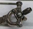
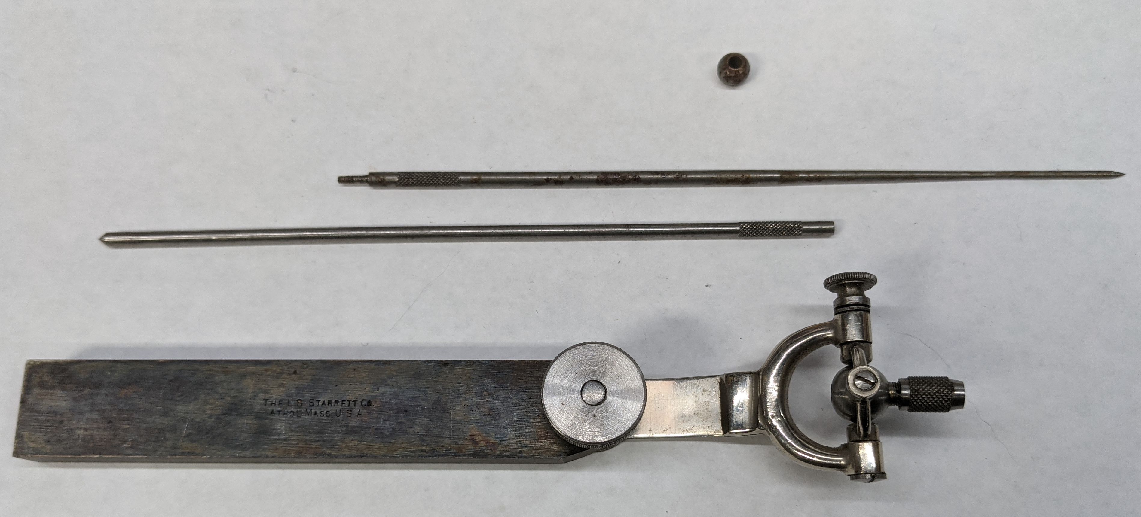
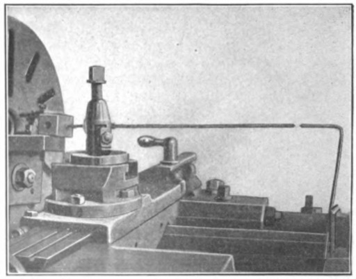
Here's a Starrett No. 65 "Center Tester." The two rods screw together to form one long pointer. They slide into a collet on gimbals (this collet tightens with a knurled screw). The gimballed unit is attached to a holder via a flat spring. One axis of the gimbals may be locked down (using the knurled knob at the top, in the photo below) to allow the device to register in a single plane only. The small ball could be slipped over the rod for use in holes (a procedure not discussed here).
Here's a closer view of the gimballed head. It's beautiful.
I don't know when Starrett introduced their No. 65. Here it is in a reasonably good scan of their Catalog 15, undated but circa 1900:
( https://archive.org/details/StarrettCatalog15)
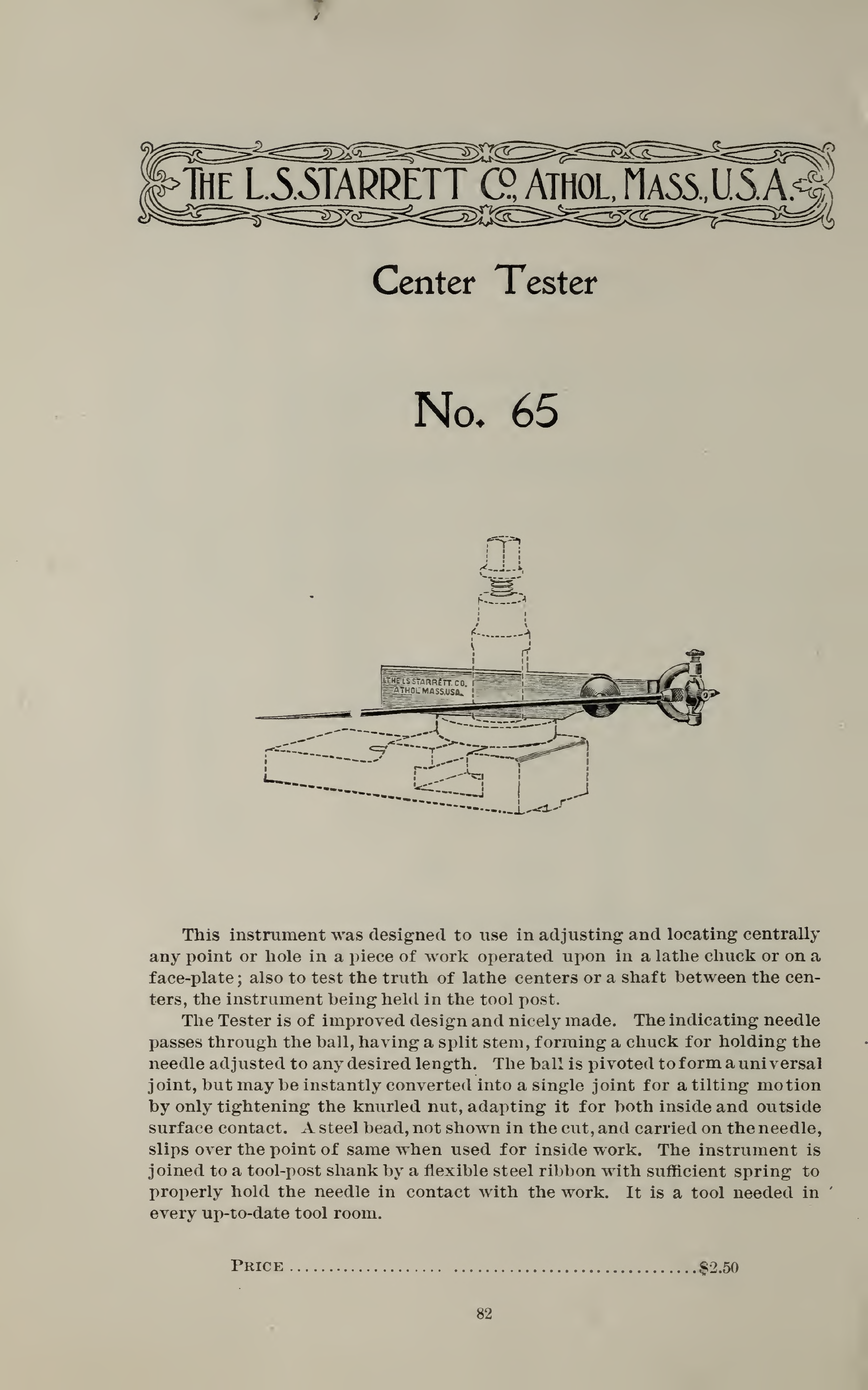
The Brown & Sharpe version was constructed differently, but equivalently. Its rods are longer (sorry for cutting off the pointy bit in the photo below). They used a separate left rod with a bent end for internal work. The holder is also larger (it won't quite fit into a BXA/250-201T tool holder, while the Starrett No. 65 will; this is the main reason I used the Starrett in the example below). I believe that there is a spring inside the "finger holder," but my unit is very stiff and I haven't yet disassembled it to verify this.
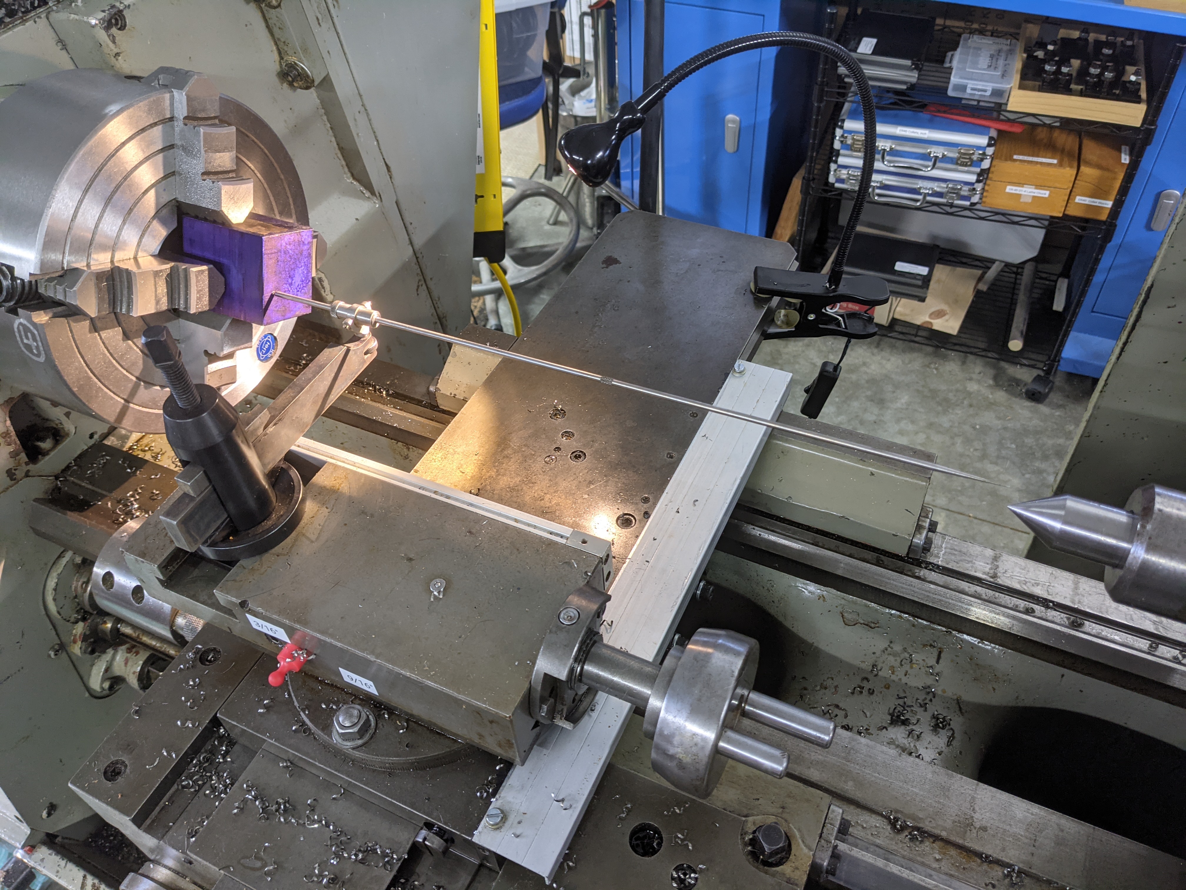
There will be plenty of photos of the Starret No. 65 later in this writeup, so here's one of the Brown & Sharp 736 on the lathe. I had to break out the lantern toolpost to mount it. I should also note that according to the B&S catalogue images I am using the mounting collet backwards in the photo below; the knurled nut should be on the tailstock side.
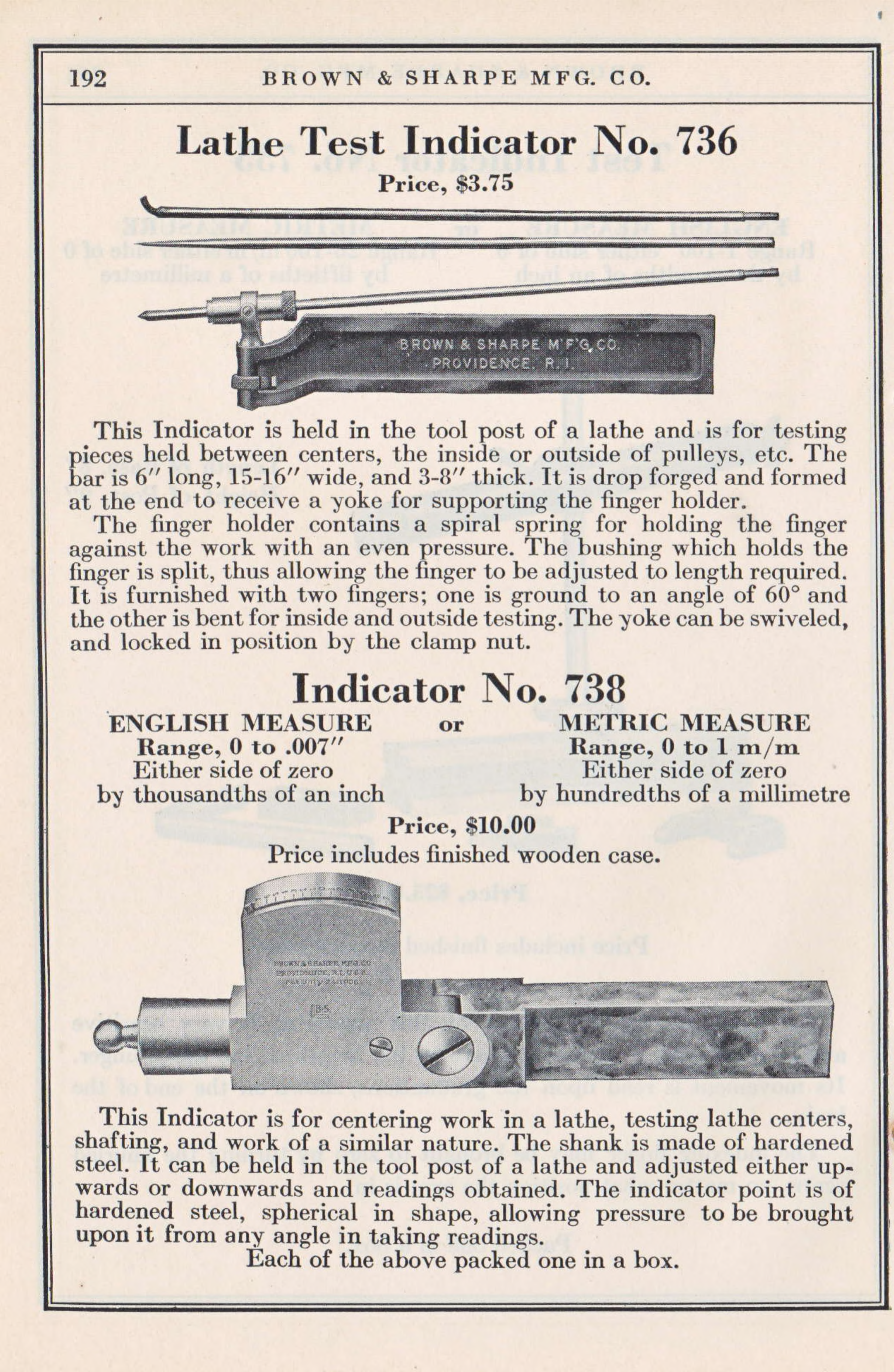
I do not yet know the date at which Brown & Sharpe introduced their version of this device. The 1904 Brown & Sharpe Mfg. Co. Catalogue (online at The Internet Archive: https://archive.org/details/BrownAndSharpeMachineryAndTools1904Catalogue) lists a No. 467 "Lathe Test Indicator" (p. 415). It is substantially the same as the later No. 736, save that its mounting bar was forged steel.
By their Catalog No. 27 (1916), this had become the No. 736 as shown in my photographs above (except that the mounting bar still seems to be forged, as opposed to the plain bar of my indicator). See: https://archive.org/details/BrownAndSharpeSmallToolsCatalogNo271916, p. 168.
Anyway, here's the No. 736 as shown in their 1924 Catalog No. 29:
( https://archive.org/details/BrownAndSharpeSmallToolsCatalog29)
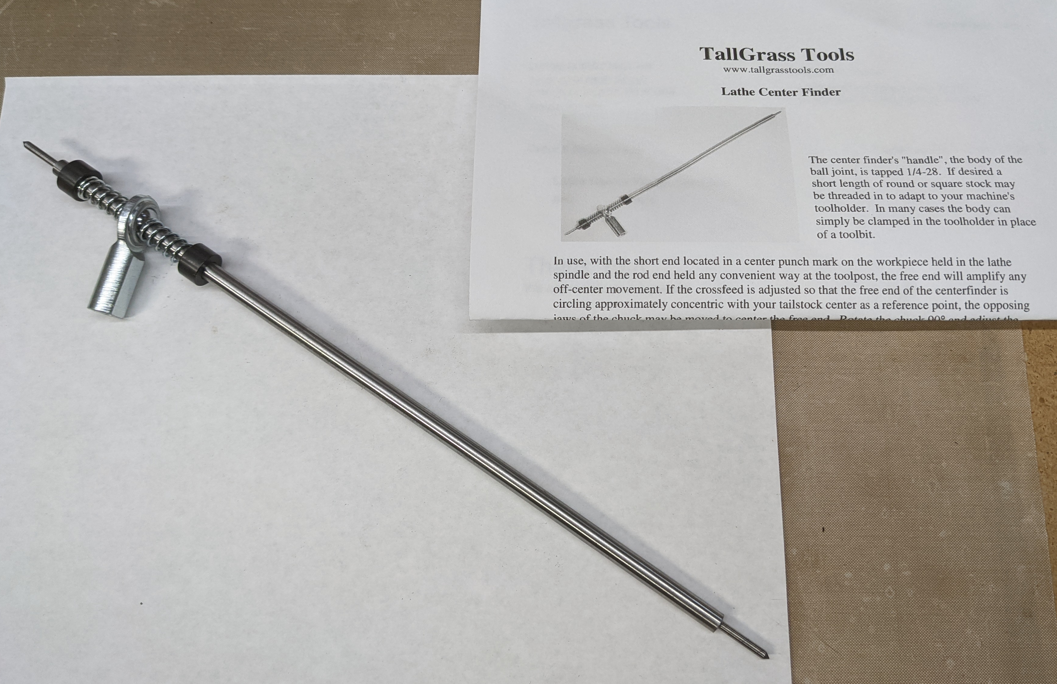
The final example that I can document photographically in my own shop is one that you can still buy new. It's made by Tallgrass Tools and is available either assembled (as I got it) or as a kit. It differs in several respects from the earlier units. The rod is one piece and is shorter overall. It employs a spherical bearing rather than gimbals or pivots. There is no provision for locking down one axis and there is no ball or bent tip for internal (/external) work. The holder portion is quite short (though sufficient to use by itself) but is threaded to allow a longer holder.
For more information on this indicator see the Tallgrass Tools website: https://tallgrasstools.com They are to be commended for keeping this and several other very nice tools in production, both in kit and finished forms.
The also make a tiny version for the popular "mini" lathes (e.g., 7x14 lathes). All of their tools are remarkably inexpensive.
The center indicator is deceptive in its simplicity. Most of the instructions I've read simply direct you to set it up and start making adjustments. This can be a discouraging process if you don't understand why you're adjusting things.
As I have come to understand the matter, there are two distinct ways to use this instrument. In the first way, the workpiece and indicator are set up and then only the workpiece is adjusted. In the second way, both the workpiece and the position of the indicator are adjusted. Once you know what you're doing it is of course possible to mix these two methods, but it seem to me to be clearest to understand them separately first.
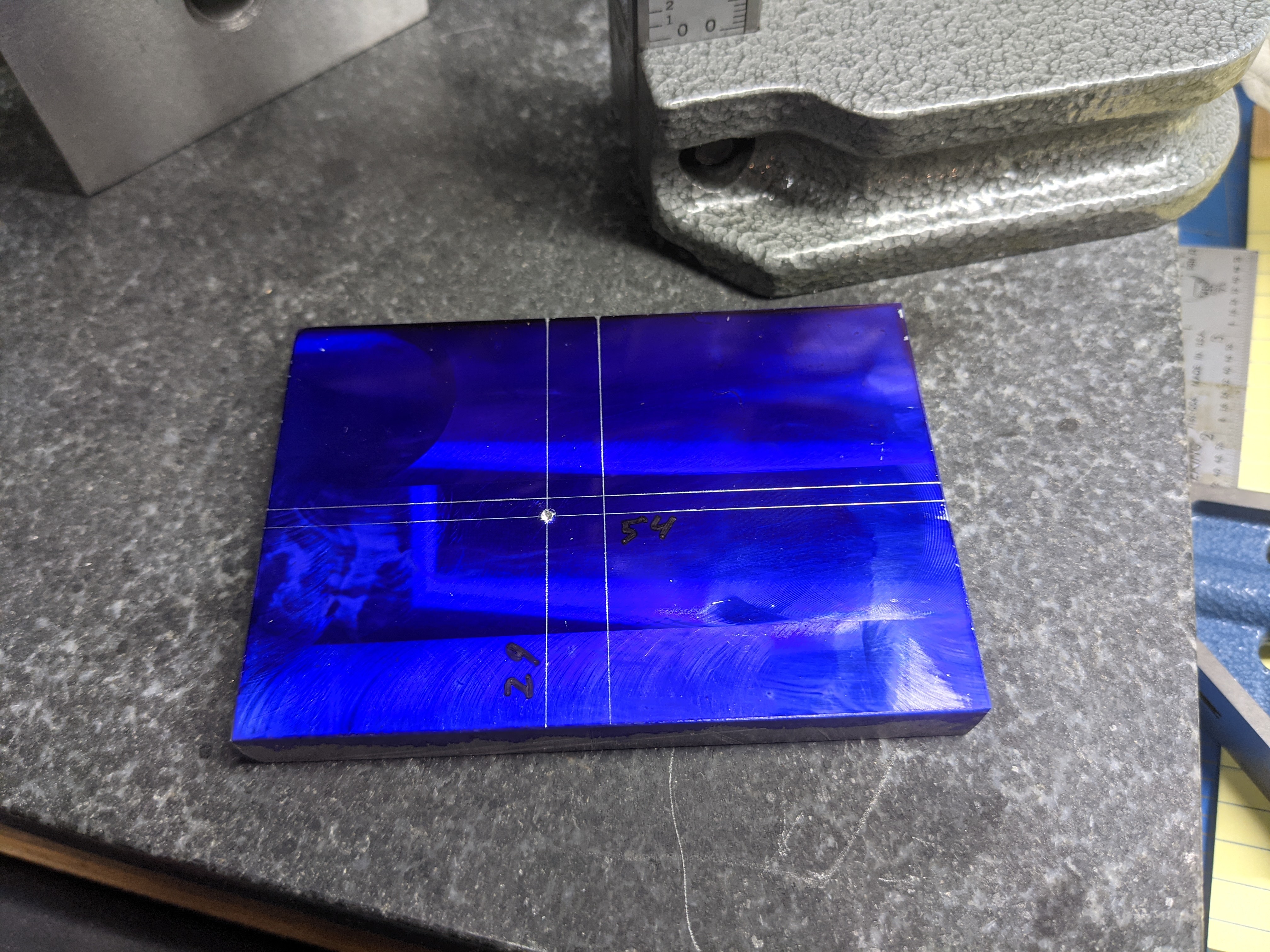
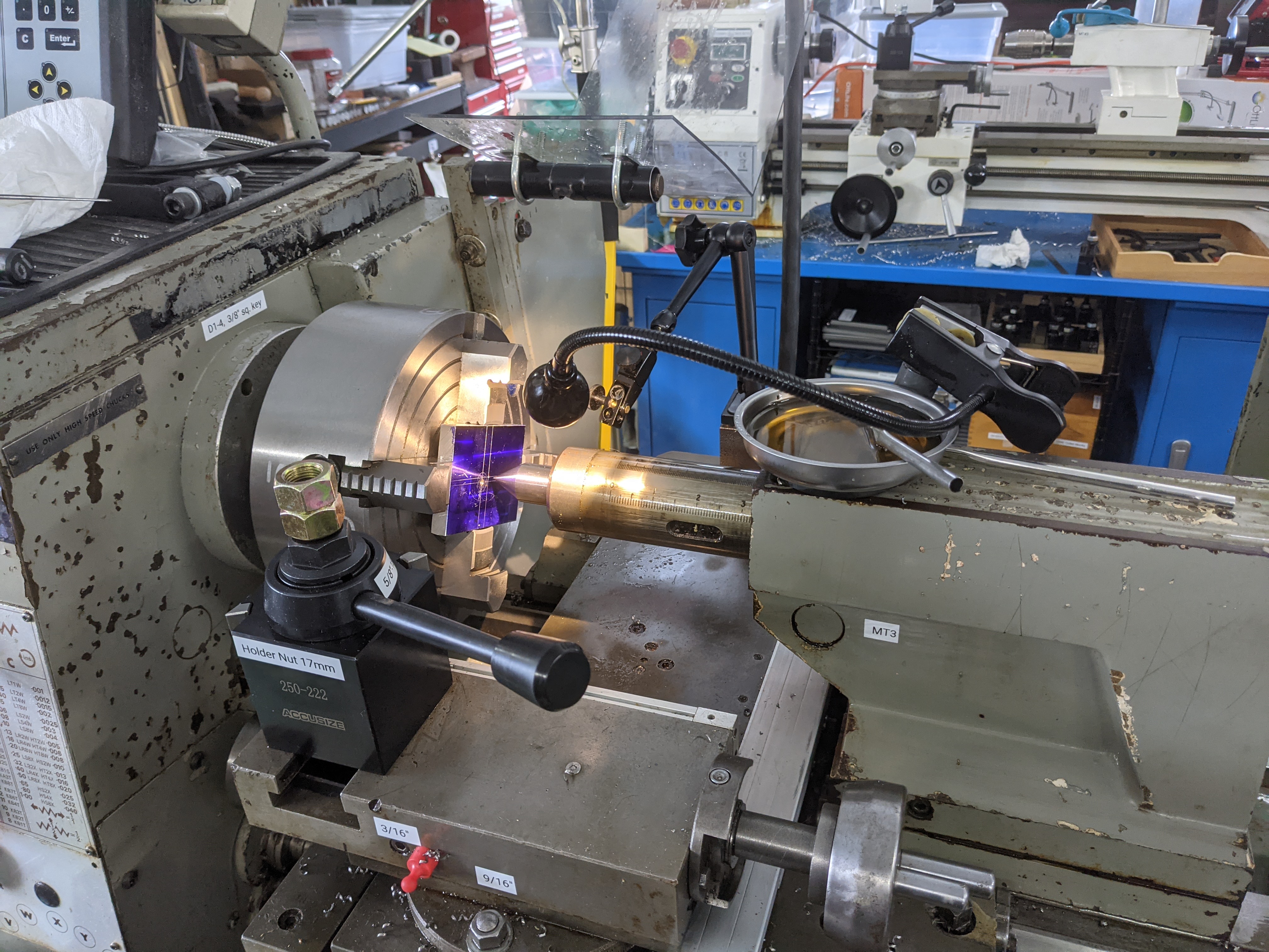
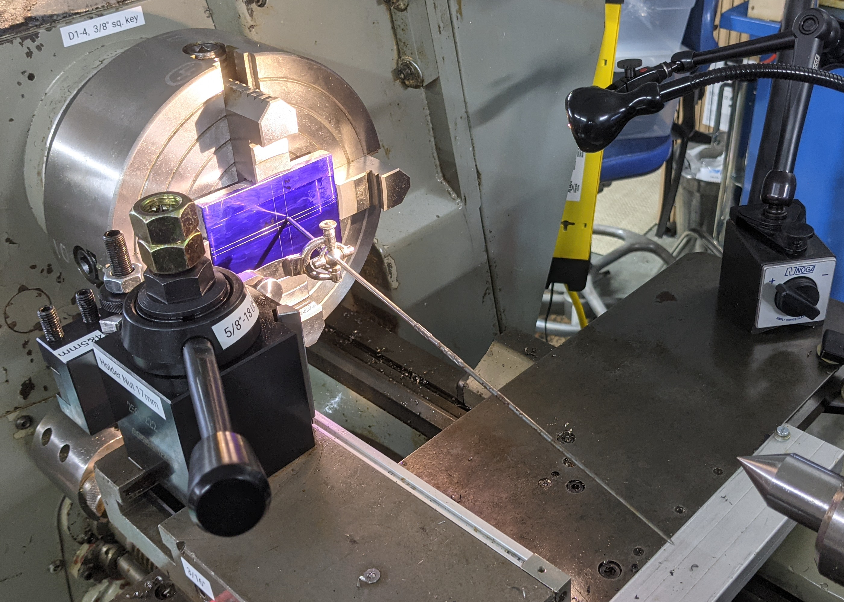
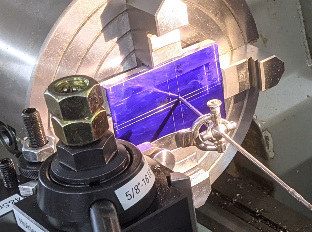
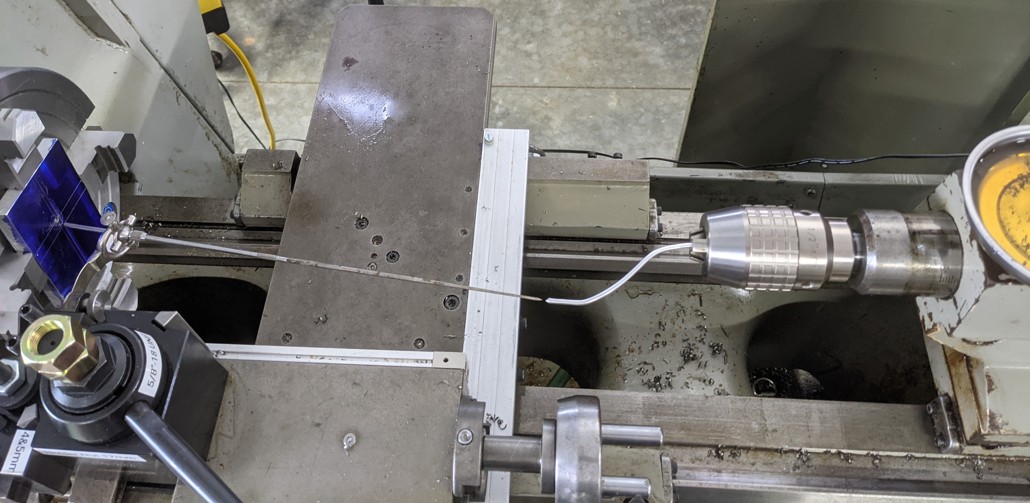
Here's an example workpiece. It's rectangular and has a punchmark for an intended hole location off-center with respect to the workpiece. I've set it up in the lathe in an independent-jaw four-jaw chuck.
(For a sense of scale, the punch mark is 29 mm from the bottom edge of the workpiece and 54 mm from the right edge. It doesn't matter, but this is on my main "big" (for me) lathe. It was made in the early 1980s and sold in the USA as a "Clausing Colchester 13 inch" (short bed), but underneath that branding it is a Colchester Master 2500 (English made). The chuck is 8" / 200 mm diameter and of Asian manufacture.)
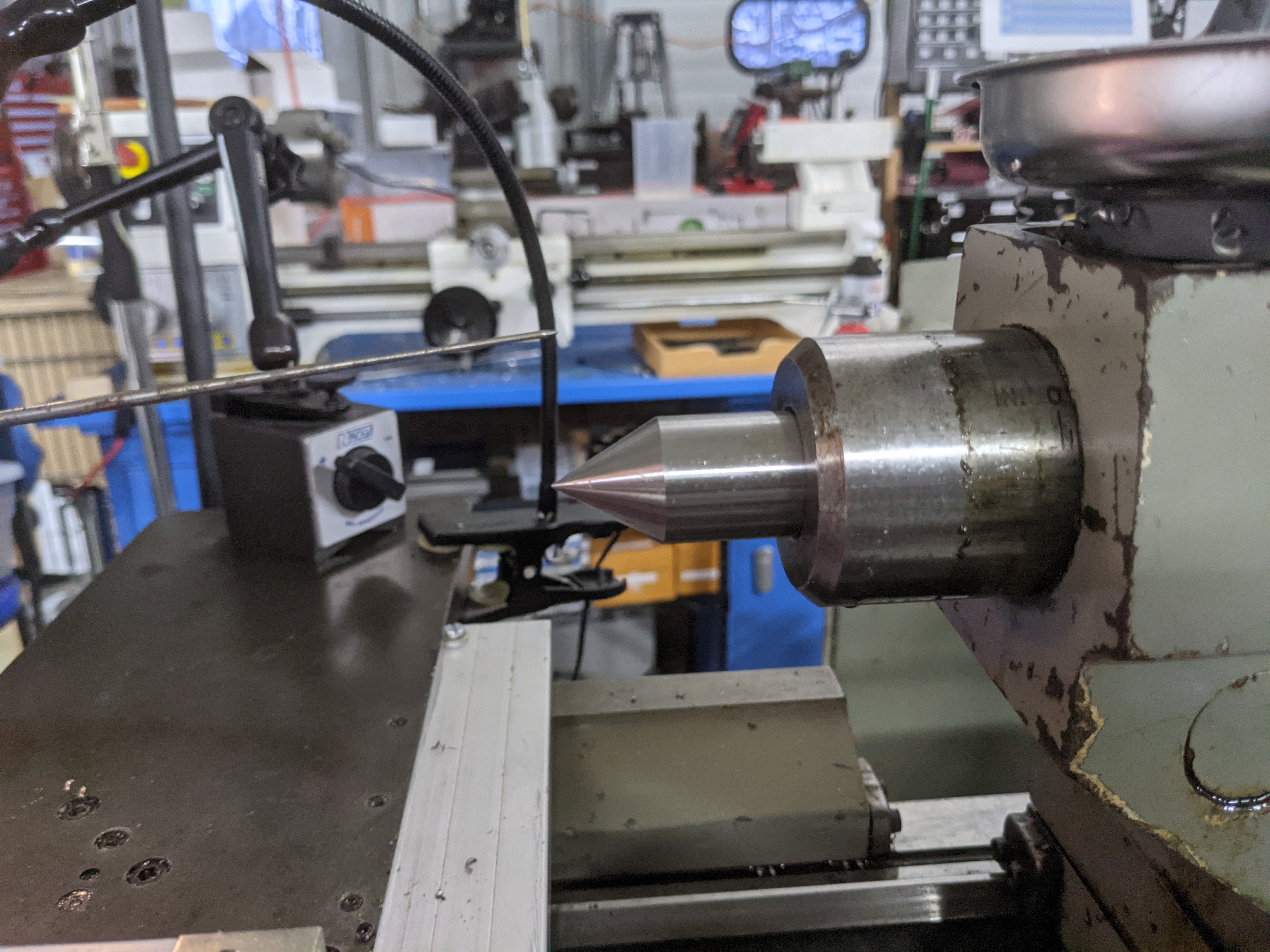
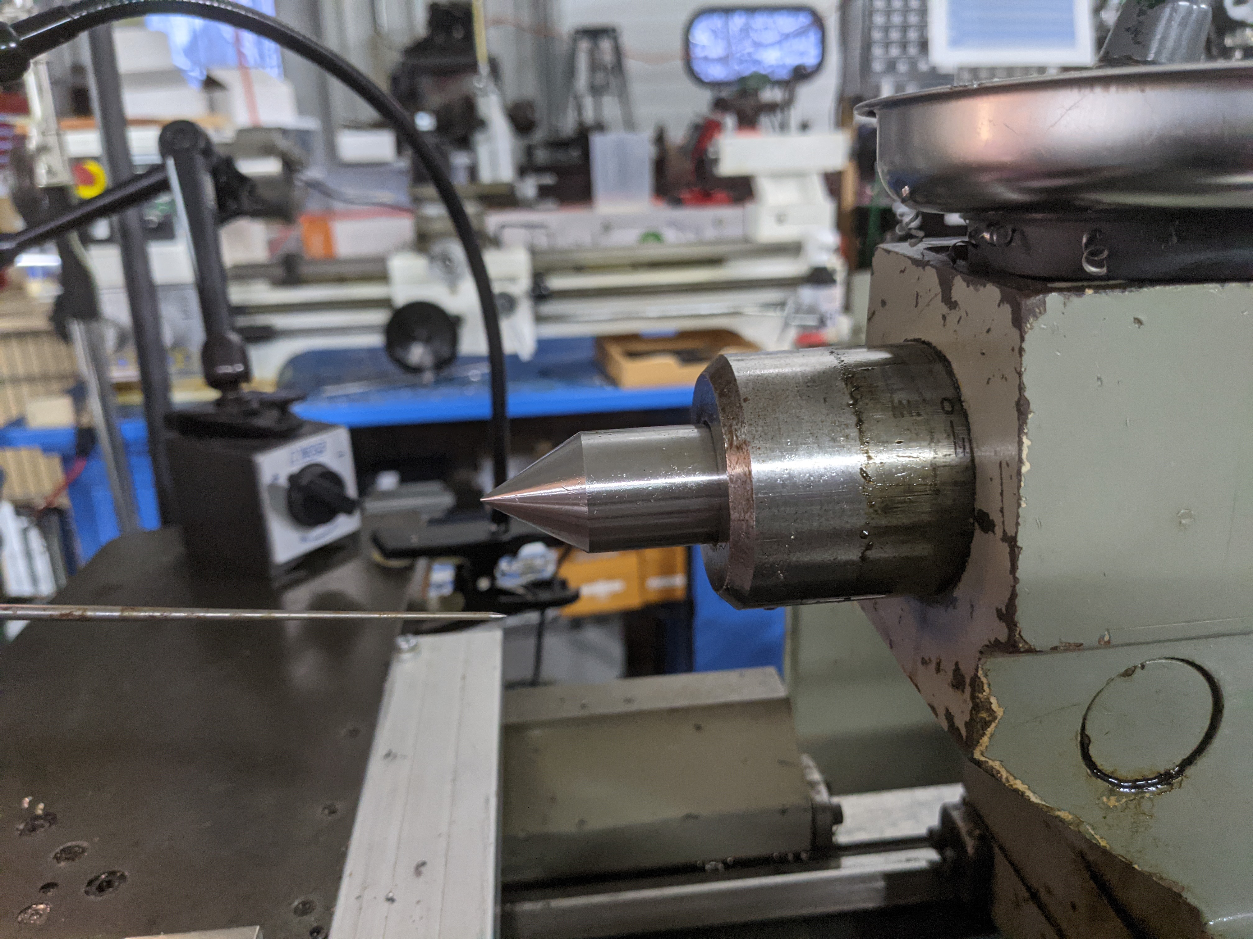
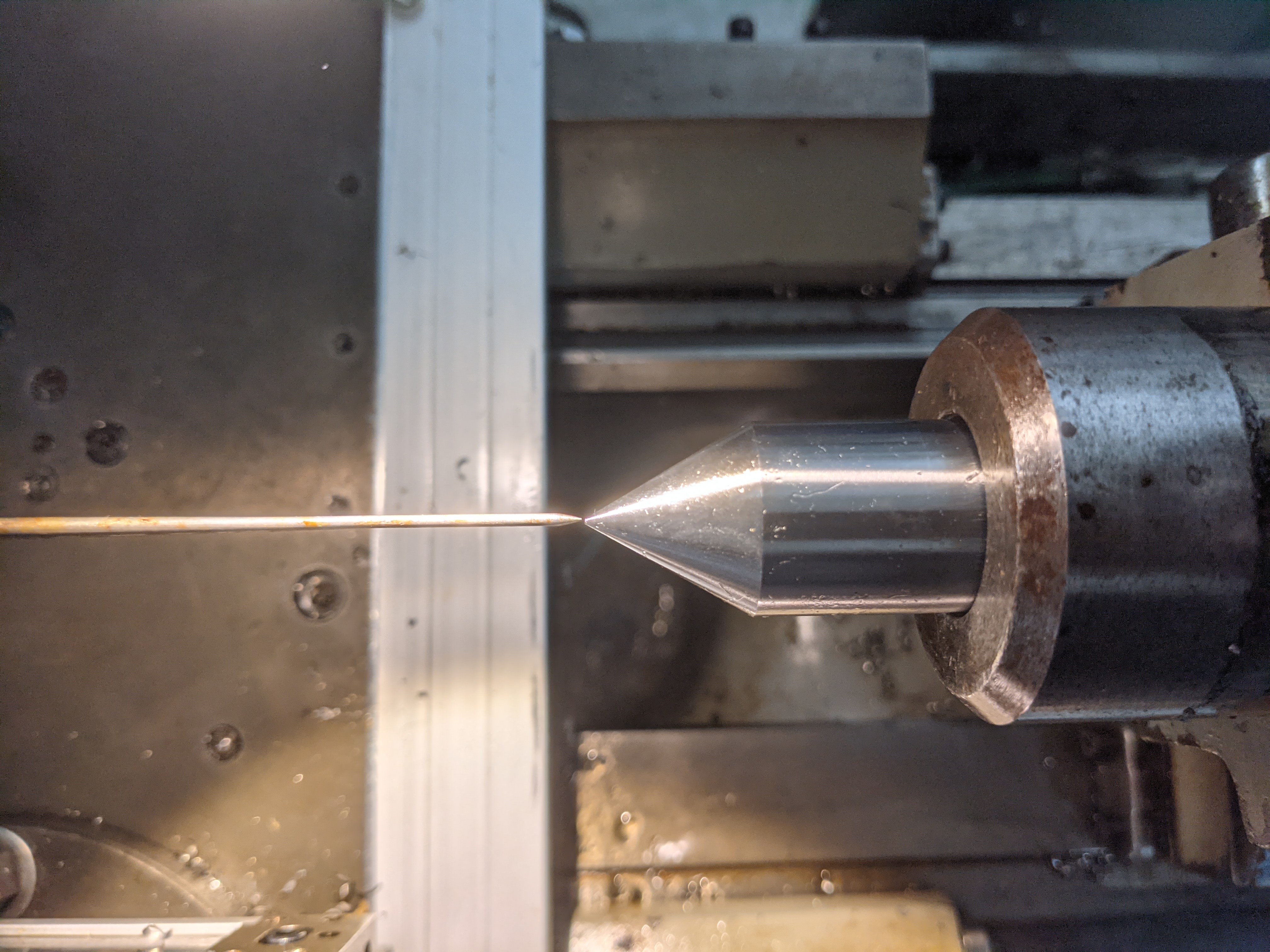
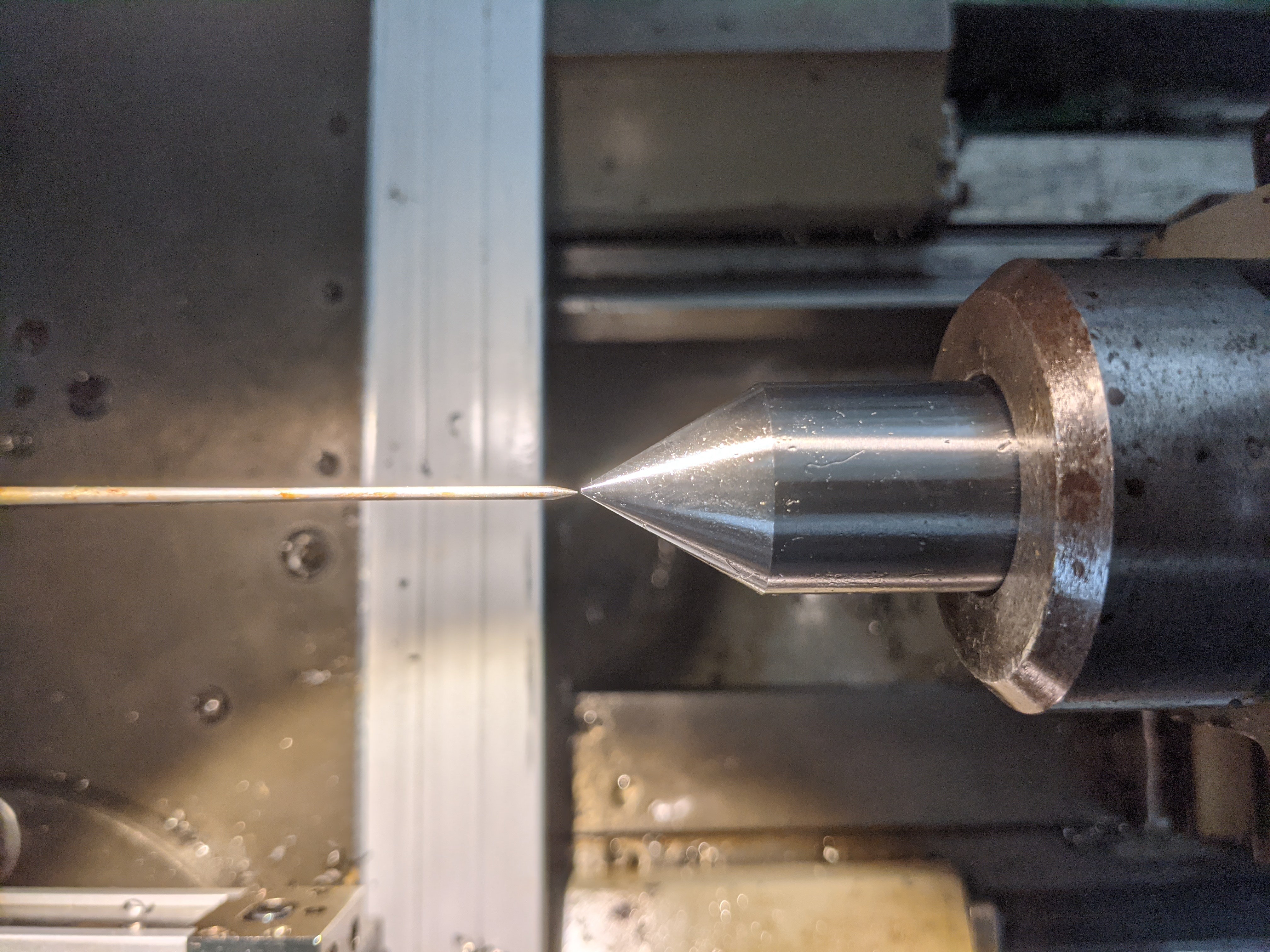
Once the workpiece is mounted, it makes sense to get as close as possible using easy but approximate methods. Put a dead center into the tailstock and bring it close to the workpiece. Using this as a visual reference, align the punch mark on the workpiece as close to center as you have the patience for.
(If you're looking closely, you'll notice that I posed this photograph some time after those above. The workpiece now has a tapped hole in it at the original punch mark. In the posed photo above, I'm lining up to a new punch mark at the center of the workpiece.)
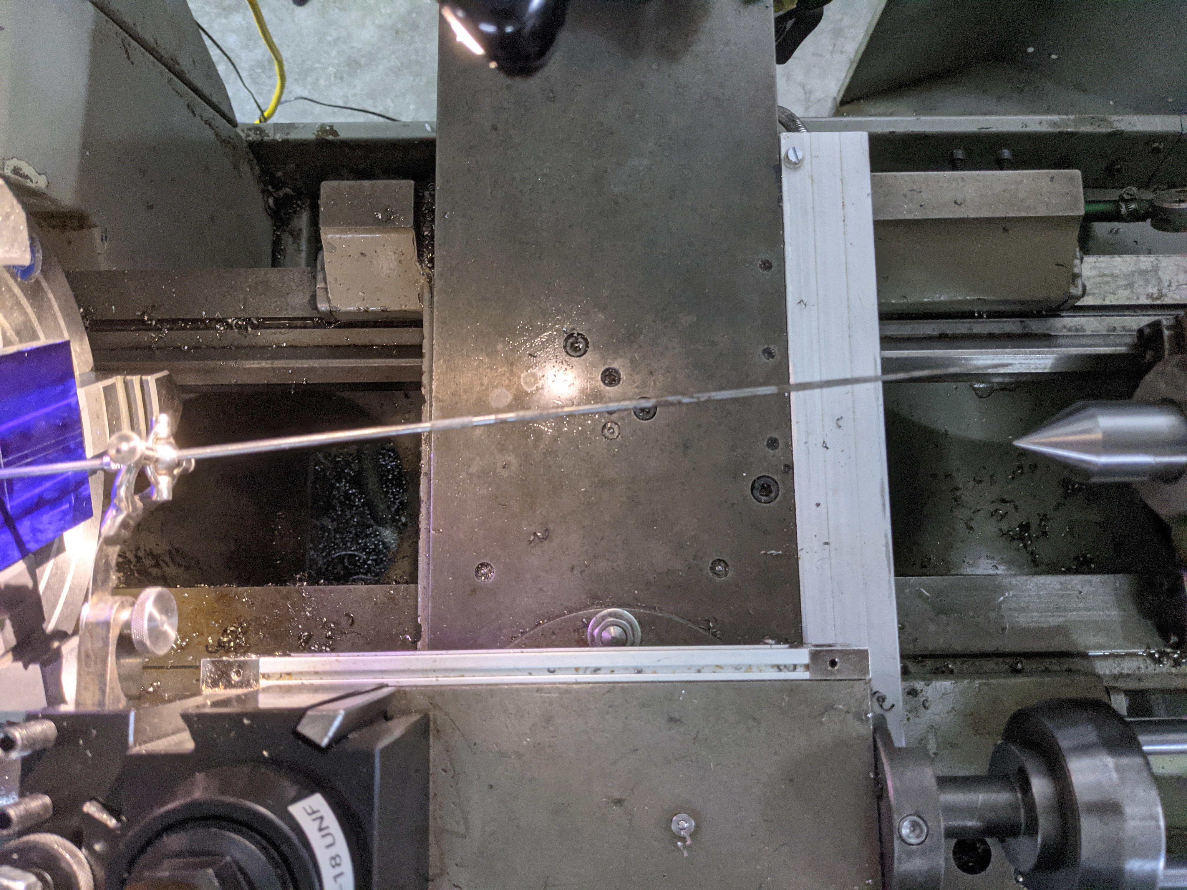
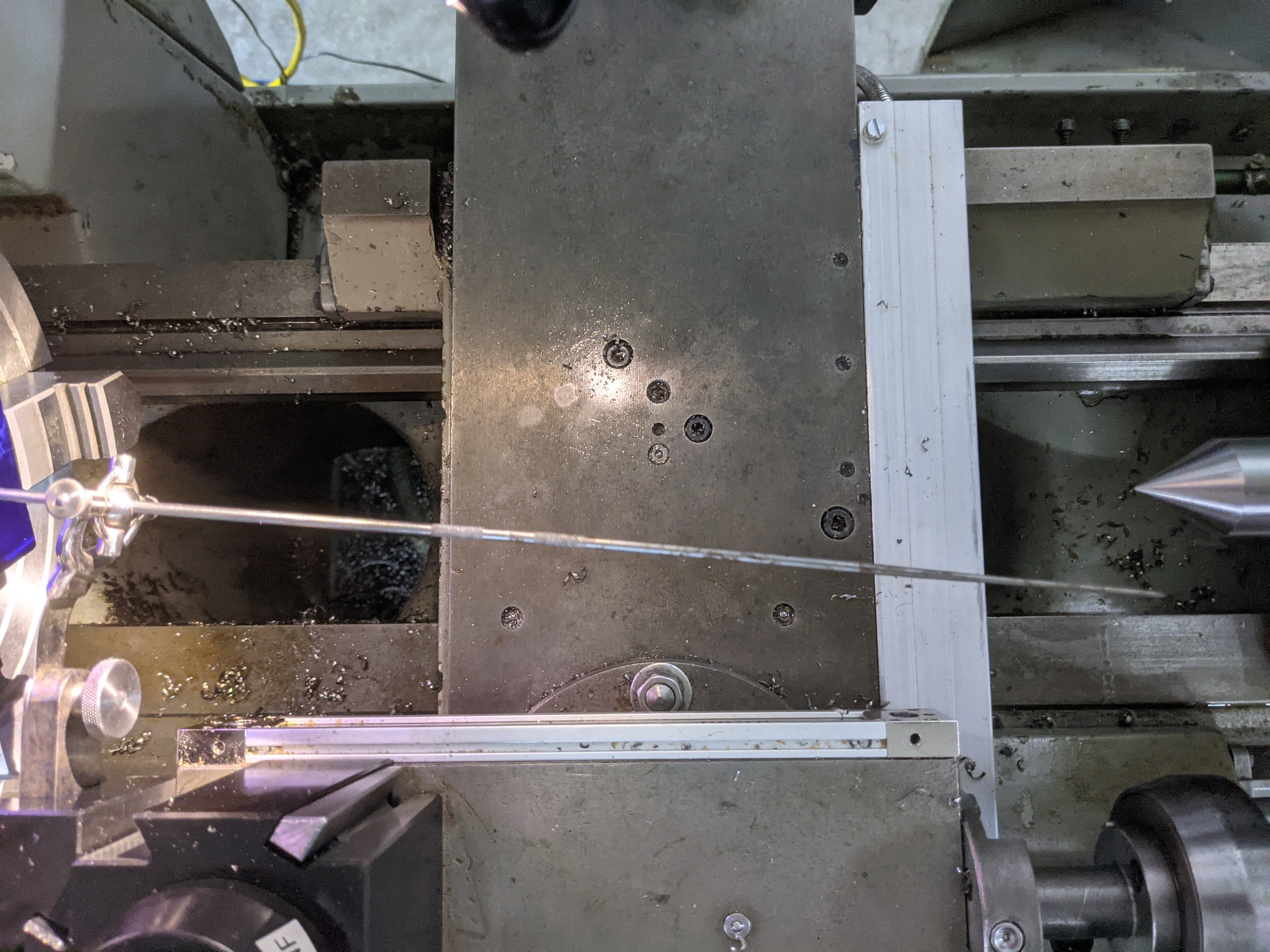
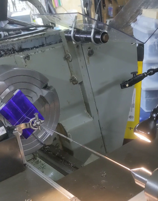
So here's the basic setup, and below that a close-up cropped from the same photograph. The centering indicator is a Starrett No. 65 "Center Tester." It is set up rather anachronistically in clone of an Aloris (wedge type) quick-change toolpost. This is the "BXA" or "250" size. The toolholder is a 250-201T, the "tall slot" version of the basic -201 toolholder.
I very carefully checked the Starrett catalog images to ensure that I had the flat spring facing the correct direction, and then failed entirely to notice that I had the gimbal backwards: the knurled nut should be on the tailstock side. In practice it doesn't matter.
Ignore the labels on the machine components. I'm a tech writer. Of course I document my machines.
It is important to realize that when you start out (in either Method 1 or 2) the center-of-rotation of the center indicator will not be on the centerline of the lathe. For Method 1 this doesn't matter. For Method 2, we'll change it.
Method 1 relies upon the basic geometrical axiom that two points determine a line.
One of these points is the center-of-rotation of the indicator. In Method 1, we keep this fixed at whatever its initial location is; we never change it.
The other point is the punch mark on the workpiece. When we start, this point revolves around the centerline of the lathe (when we rotate the spindle/chuck). The punch mark is stationary only if it is coincident with the centerline of the lathe spindle.
So, geometrically, if the line is stationary then we know that both of these points are stationary, and we therefore know that the punch mark is centered. Method 1, therefore, is to adjust the workpiece until the center indicator (more particuarly, its long pointy end, which amplifies the motion of the punch mark) stops moving when the chuck/workpiece is rotated.
You won't get it in the first round of adjustments. It will take several.
It may be tempting to move the indicator, especially if it happens to be relatively far from the lathe centerline. Yes, you can do this, but that's part of Method 2. Don't do it unless you understand what is going on in Method 2.
It is important to realize that in Method 1 the pointy end of the center indicator will not necessarily be rotating around the tailstock and we are not trying to align its rotation in any way with the tailstock. Indeed it is easier to see things if we just pull the tailstock back out of the way. The pointy end of the center indicator will just be revolving in space. Our objective is to minimize that rotation - ideally, to reduce it to nothing (tip stationary).
Some explanations of the use of the center indicator leave it at this. See for example (referring to the collection of "Earlier Descriptions," below): Cheney in The Mechanical Engineer (1887) or Jones in Modern Toolmaking Methods (1914) .
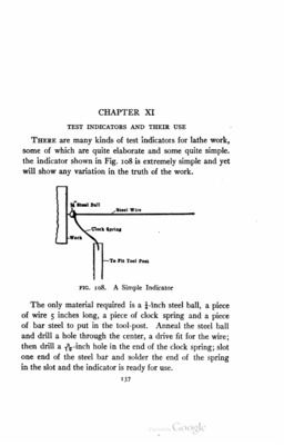
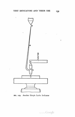
But it can be difficult to judge the motion of a thin sharp pointer in space without references. So other sources luggest supplying such a reference. For example, Fred Colvin, in Engine Lathe Work (1909) mounts a pointer to the bed of the lathe:
This pointer is simply adjusted (and re-adjusted) as necessary so as to be as close to the center of rotation of the indicator's tip as possible.
In a pragmatic simplification of this, Burton, in Popular Mechanics (1971) uses a soft aluminum wire fixed in a drill chuck in the tailstock. I can't reproduce his photograph, but I can reproduce the setup:
Another option, more modern but more complicated, is to hold a pointer in the magnetic-base indicator holder of your choice.
(In both of the photographs above, the indicator is very nearly stationary. I didn't work through this setup quite as finely as I did in the example for Method 2, below, but I did bring things pretty close to centered. Dyslexia aside (moving the workpiece the direction opposite the one intended), it didn't take very long.)
Rather than adjusting arbitrarily, it is best to adjust the work in one plane at a time. So consider an imaginary plane perpendicular to the chuck which runs through the centerline of the lathe. Look at the lathe and indicator square on to that plane. Now rotate the chuck and observe the motion of the indicator's pointer. It will have a maximum and minimum in the plane.
If the work is held on a faceplate, then you just loosen it and tap it within that plane to reduce the pointer motion. Late 19th and early 20th century sources tend to assume that you're doing faceplate work, so this is all they consider. ( Burton, in Popular Mechanics (1971) , does illustrate work in the four-jaw chuck, but for all his detail he does not consider the problem we're about to see.)
If the work is held in the four-jaw chuck, however, things aren't so easy. The surface of the chuck has two axes of its own, defined by the two pairs of opposing chuck jaws. Unless it happens that the punch mark is exactly on one of these axes, then when the punch mark intersects your viewing plane (and the pointer is at its maximum or minimum position) the chuck jaws will not be in this plane.
But you can only adjust the workpiece using the chuck jaws. So if you try to adjust the workpiece when the pointer is at its maximum/minimum positions in the viewing plane, you'll be adjusting at an angle to what you intend. This way madness lies.
The solution to this is to keep the viewing plane firmly in mind and judge the maximum and minimum pointer positions only when an opposing pair of chuck jaws are in this plane. Then make your adjustment, even though the pointer will not be at its absolute maximum or minimum distance from its rotational center.
I am aware of no source in the literature which mentions this problem.
The objective of Method 2 is identical to that of Method 1: cause the center indicator to remain motionless as the workpiece/chuck turns. The difference is that Method 2 takes advantage of the fact that lathes come with a convenient built-in center: the tailstock. (More specifically, a dead center mounted in the tailstock taper.)
Before getting into it, I'll establish a couple of preliminary points about tool posts and geometrical nomenclature.
I am presenting the example here in a way which locks things down to coordinate systems more than is necessary in the general case.
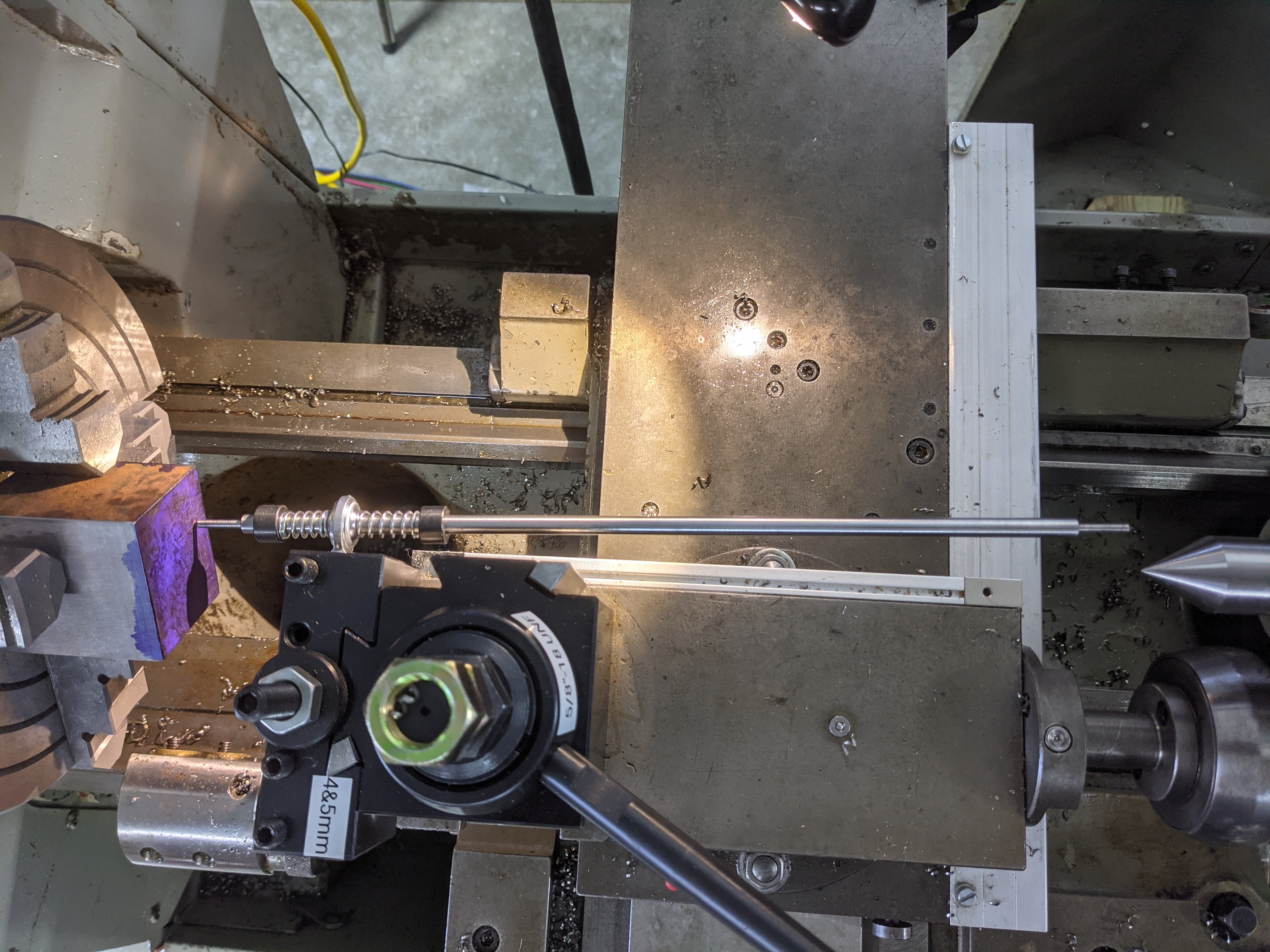
In particular, I'm holding the centering indicator in an Aloris-style "quick change" tool post. This means that all of my adjustmens of the indicator will be done entirely along either the X axis (moving the cross slide) or the Y axis (adjusting the tool holder height).
However, in older practice the centering indicator might well have been held in what is called a "lantern" or "rocker" style of tool post. Such a tool post not only permits simultaneous adjustment in the X and Y axes (and the Z axis, as well) but indeed makes it difficult to adjust only one axis. If you're using such a toolpost, realize that while the principles of the operations described here remain the same, the actual manipulations will be a bit more fiddly.
As an aside, the single trickiest manipulation in this entire process was vertically setting the toolholder. You have to snug it up and keep downward and outward pressure on it to keep it from jumping around. I might have done better by using my traditional "lantern" style toolpost ... or buying a genuine Aloris toolpost.
I'll use the standard coordinates for a CNC lathe. These were based on earlier conventions with the mill, so the long axis of the lathe is the Z axis because it is the spindle axis. The X axis is the cross-slide direction. The Y axis is vertical.
So the XZ plane is a horizontal plane through the centerline (Z axis) of the lathe. The YZ plane is a vertical plane through the centerline.
Here's a view down onto the XZ plane:
The overall procedure consists of two operations which are performed alternately until the result is deemed to be close enough. I'll call them A and B. In theory, just performing them once (A then B) could work, but the level of skill that I possess does not allow me to get A perfect the first time. (A review of the literature indicates that this procedure usually took several iterations.)
Operation A attempts to bring the center of rotation of the indicator onto the spindle centerline (Z) of the lathe. When this situation is achieved, then the rotation of the punch mark on the workpiece will cause the pointer end of the indicator to rotate symmetrically around the tailstock center.
Operation A is accomplished with two adjustments: adjusting of the indicator in the X (cross-slide) and Y (tool post) axes to some new position in the XY plane which is closer to the Z axis. (As noted earlier, if you're using a lantern/rocker tool post you'll be adjusting in X and Y simultaneously).
During Operation A, the workpiece is left untouched.
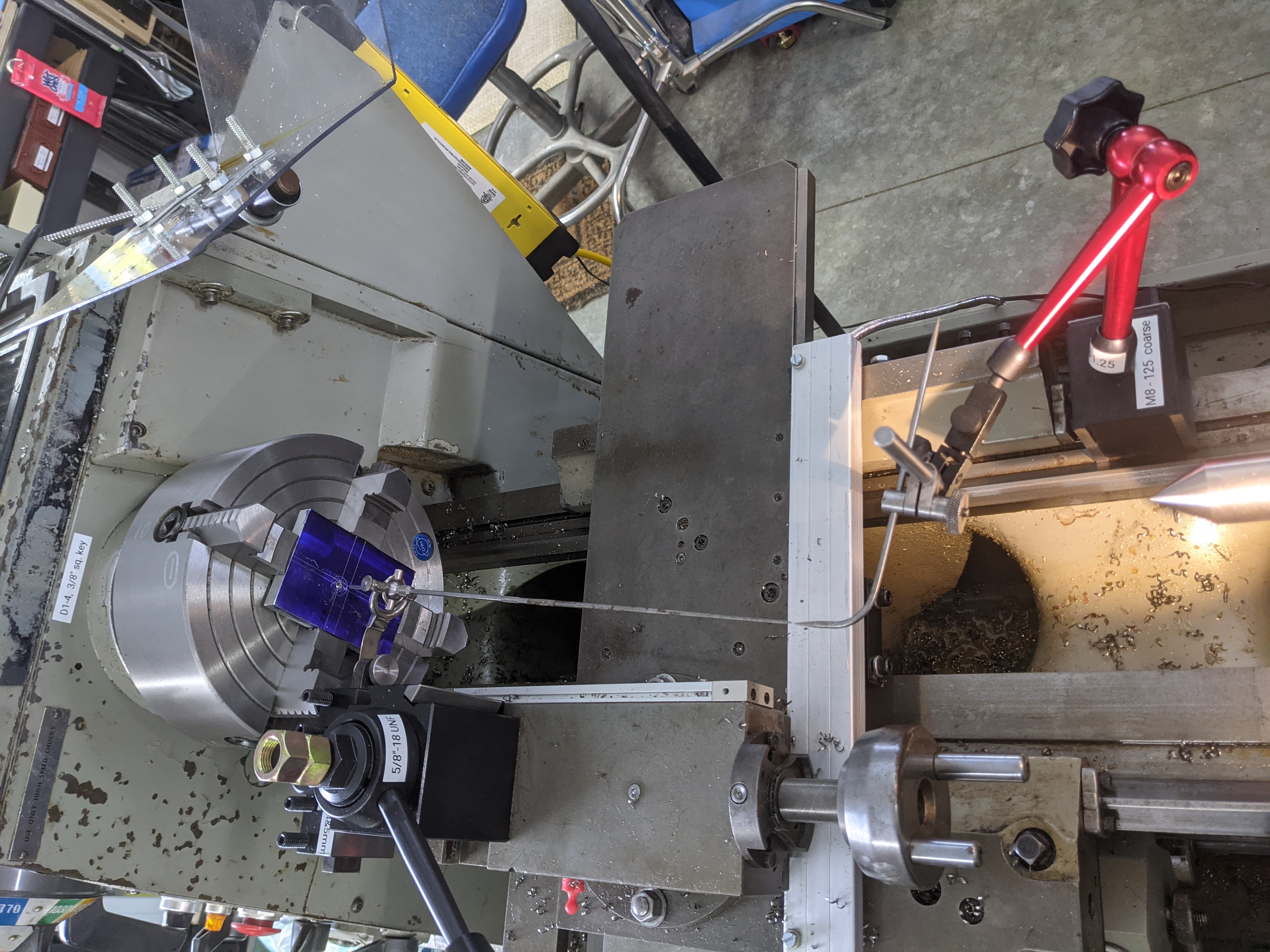
Here is an attempt at operation A, viewed from above (actually this shows only its results in the XY plane in response to motions of the cross slide). You can see by comparison to the photograph above that I've come a little closer, but still have a way to go.
Here's the view in the YZ plane, showing the results from adjusting the tool holder height. Not quite as good.
This is easier to say than to do. It can be difficult to estimate the distances between the tailstock dead center and the indicator's pointer. At the beginning, the pointer may be some distance from the tailstock and perhaps not even revolving around the tailstock. Remember, there isn't a scale to read - you're just estimating space.
It is also important to ignore the position of the chuck jaws when doing this. As was discussed in Method 1, the maximum distance of the pointer from the dead center in the XY or YZ planes is most likely not when the chuck jaws are in those planes.
It is therefore important to look squarely at the XY plane when moving the cross slide and squarely at the YZ plane when moving the tool height ajustment. Do not move around looking for the maximum distance between the indicator pointer and the tailstock center.
Especially the first time through, it's ok just to get close. It will be easier in later iterations when the distances are shorter.
"Operation B" of Method 2 is identical to the entirety of Method 1: adjust (only) the workpiece so that the motion of the pointer is minimized (or zero).
If the indicator's center of rotation is on the Z axis, then upon successful completion of Operation B its pointer will be stationary and lined up perfectly with the dead center in the tailstock. You're done.
If the indicator's center of rotation is still a bit off, and if you get the pointer to a stationary state, then to complete Method 2 you should iterate and start over again with Operation A to try to get everything lined up on Z. But, actually, once the indicator's tip is stationary then the punch mark is centered and, really, you're done.
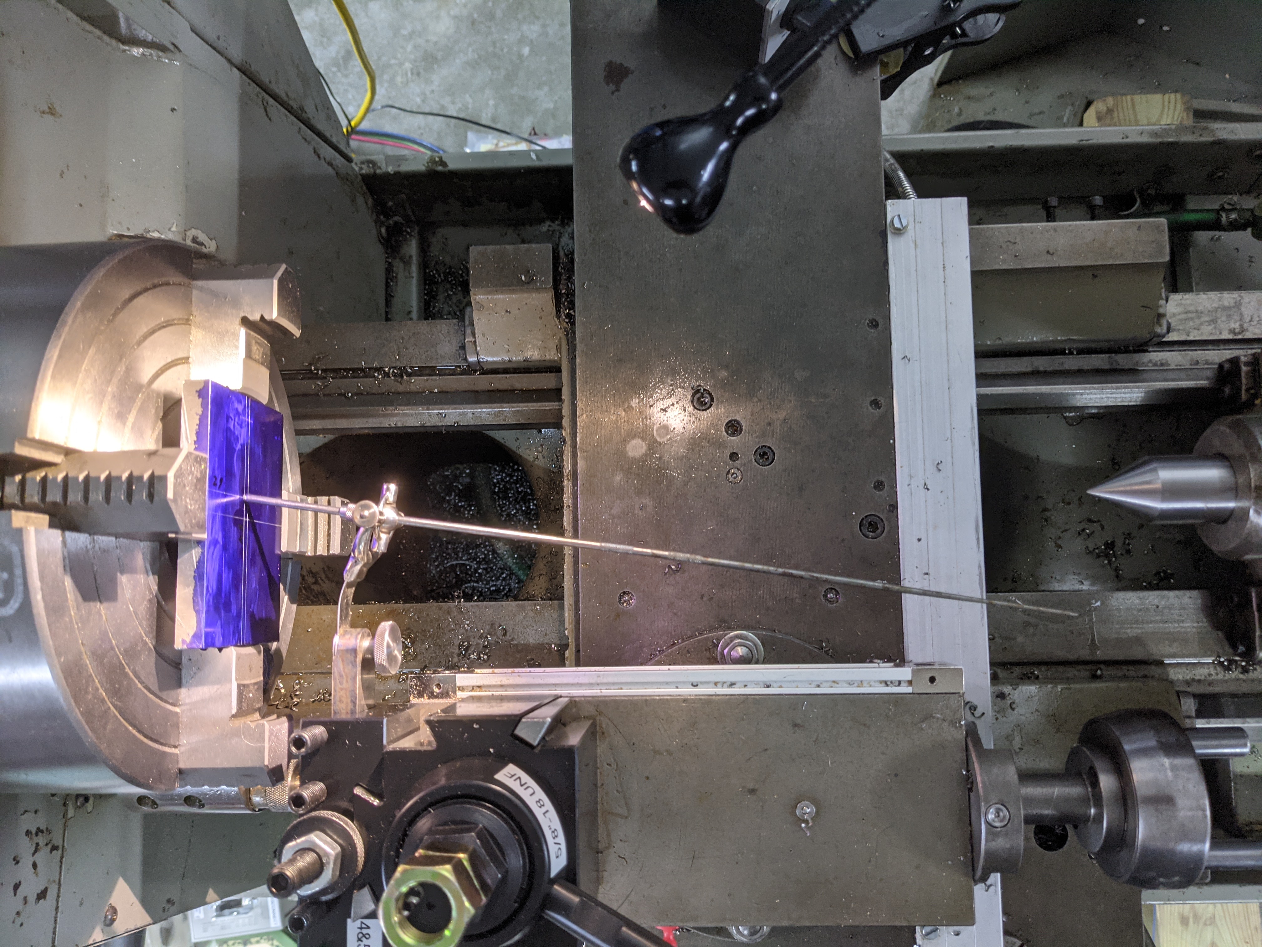
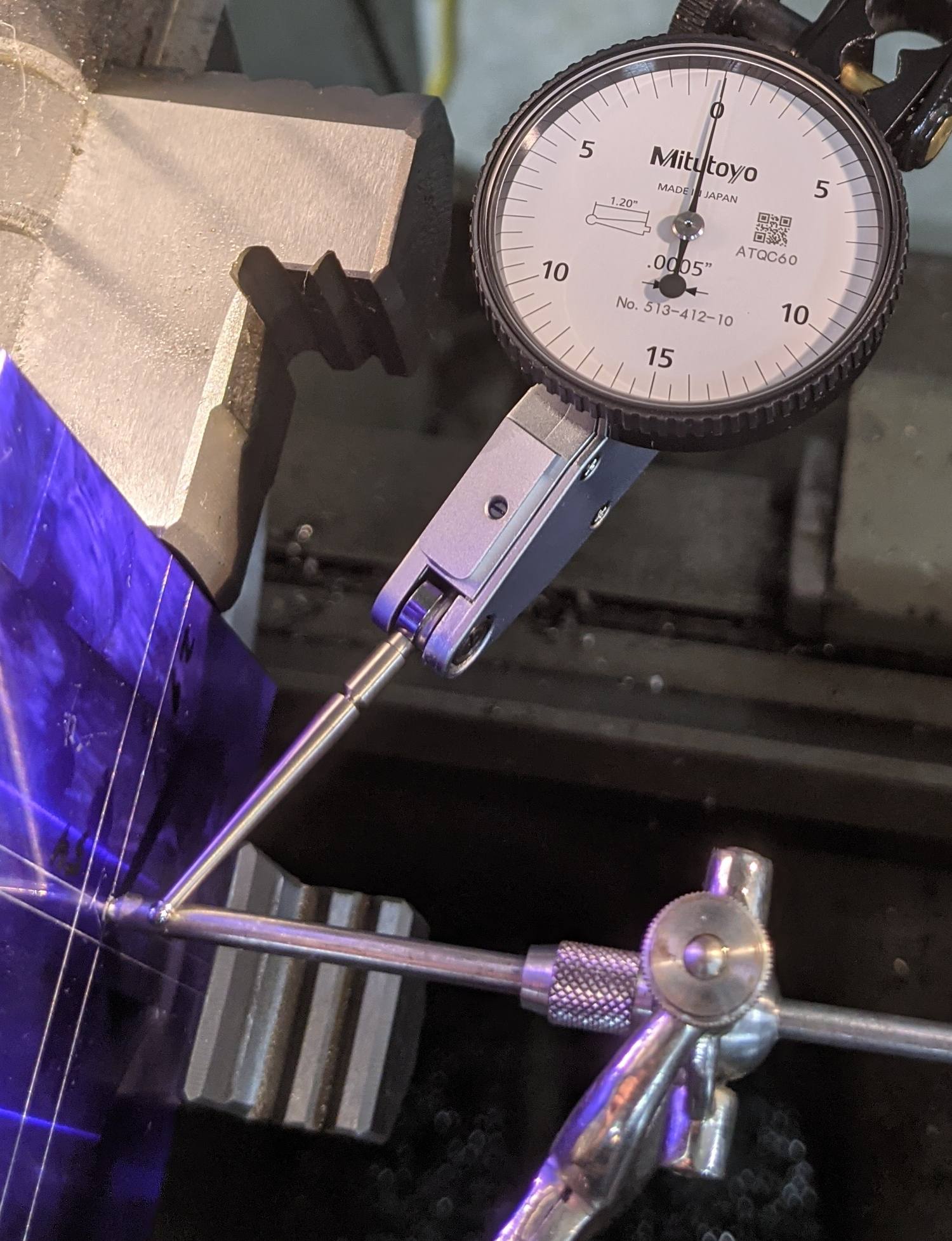
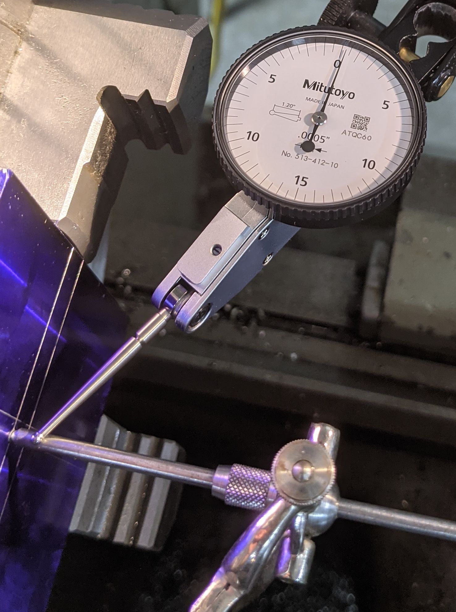
Here are a couple of photos of this. I'm getting closer:
After a few iterations (I forget how many; three or four on this, which was only my second time doing this procedure) I had a hard time seeing movement at the pointer end. So to doublecheck things I put a modern dial test indicator on the century-old centering indicator just to check. I should emphasize that I did this only after I finished the centering operation - I didn't use the DTI to help/cheat. The result was a runout of about 0.000,3 inches, which is more accuate relative to the punch mark than my layout of the punch mark itself.
(Each tick on the indicator is 0.000,5 inches.)
Although it really isn't necessary, here's a video of the lathe running at a very slow speed after the centering. (While doing the centering I rotated the chuck by hand, not under power.) The image below may or may not just play the video if you click on it, depending upon your browser. If it doesn't, then right-click (or whatever you do) and download it and view it offline. Warning: The sound is rather loud - the combination of the lathe motor and my phase converter. You might want to turn down your volume before playing this, as the sound contributes nothing but industrial ambiance.
One last observation: The advantage (in general) of a "quick-change" toolholder isn't so much the quickness of swapping the holder in or out but the fact that the tool's height in the holder is set and need not be re-established on each use (as is the case with the lantern/rocker toolpost). If you plan to use Method 2 often, it might be worth leaving the indicator body in a dedicated toolholder. This would reduce Operation A to only one adjustment (the cross-slide / X).
Several authors specify Method 2, although sometimes they do this implicitly. For example:
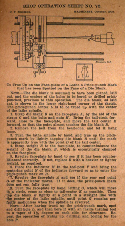
Van Dervoort, in Modern Machine Shop Tools (1903) says that "By properly setting the instrument this circle will be described around the tail center, and when the work is exactly centered the pointer remains stationary in front of the tail center." (p. 92)
The "Shop Operation Sheet No. 76" in Machinery, Supplement (1908) seems a little confused on the matter. It tells you to turn the face plate by hand and to "let" the pointer's circular movement "come as close to the tail-center as possible." It never tells you how to do this; presumably you manipulate the indicator in the lantern/rocker toolpost.
Colvin, in Engine Lathe Work (1909) adopts an intermediate position. He has you adjust the indicator by eye (not by observing its motion) "as near the center of the lathe a possible" but then he has you adjust only the workpiece, nothing that the pointer "tells the story whether it is sighted by [i.e., aligned to] the dead-lathe center or not." (p. 138) (Also, later he employs Method 1 with an adjustable wire reference for the indicator pointer. See p. 144.)
The Tallgrass Tools instructions specify Method 2, but they mention only adjusting the cross-slide, not the tool height in order to cause the indicator tip to circle "concentric with your tailstock center."
Having now employed both methods, I can't decide. Method 1 is clearly faster, though it probably will involve setting up some kind of reference point. Method 2 requires more adjustments/steps, but there is a certain symmetric solidity about having everything lined up first concentric with and then right on the spindle centerline. Also, if you already have the Y-axis (tool holder) setting of Operation B established, moving the cross-slide (Z) to achieve concentricity around the tailstock center won't take long. You pick; it's your pointy stick.
The survey here cannot possibly be complete. Things such as center indicators were perennial favorites for clever mechanics writing letters to the editors of the journals. It is, however, comprehensive enough to give an idea of the scope of invention for even this simple device.
I haven't included the Starrett, Brown & Sharpe, or Tallgrass Tools center indicators below, as they've already been covered.
An article by W. L. Cheney in The Mechanical Engineer in 1887 illustrates a gimbal-mounted center indicator. Cheney calls this 'a center indicator or "wriggler"'. His method of using it is to minimize motion without employing any reference point ("Method 1," above).
Cheney, W. L. "Modern Machine Shop Methods, No. 3: Jig Making." The Mechanical Engineer. New Series, Vol. 8, No. 7 (April 9, 1887).
Digitized by Google from the University of Illinois at Urbana-Champaign copy. Google ID: AFcnAQAAMAAJ. Here is an extract of just this page (also linked from the image above): cheney-centering-indicator-mechanical-engineer-v13-n7-1887-04-09-p77-google-AFcnAQAAMAAJ-uiuc.pdf
(As an aside, the tool now known as a "wiggler" is quite different from the center indicator.)
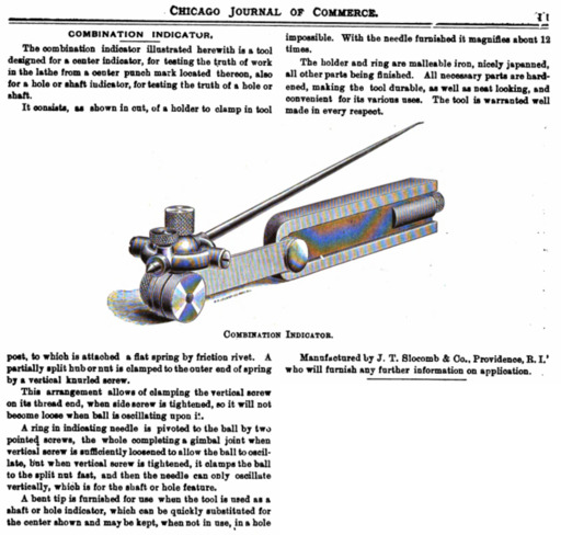
"Combination Indicator." Chicago Journal of Commerce. Vol. 69, No. 21 (November 21, 1896): 11.
Digitized by Google from the New York Public Library copy. Google ID: c4hRAAAAYAAJ. Here is an extract of this trade note from the complete volume (clicking on the image above links to the same PDF): slocomb-combination-indicator-chicago-journal-of-commerce-v69-n21-1896-11-21-p11-google-c4hRAAAAYAAJ-nypl.pdf
Grening, John A. "Locating Holes." Home Study for Machinists, Steam Engineers, Etc. Vol. I, No. 4 (November 1897): 61-63.
Digitized by Google from the New York Public Library copy. Google ID: BIs7AQAAMAAJ. Here's an extract of the article: grening-locating-holes-home-study-for-machinists-v1-n4-1897-nov-pp61-63-google-BIs7AQAAMAAJ-nypl.pdf (I haven't presented an image from it since none of the illustrations in it are relevant here.)
Grening, John A. "The Lathe Indicator and the Center Indicator." Science and Industry. Vol. V, No. 10 (November 1900): 542-545.
Digitized by Google from a University of California copy. Google ID: ppUPAQAAIAAJ. Here is an extract of this article from the complete volume (clicking on the image above links to the same PDF): grening-lathe-indicator-and-center-indicator-science-and-industry-v5-n10-1900-nov-pp542-545-google-ppUPAQAAIAAJ-uc.pdf
Van Dervoort, William H. Modern Machine Shop Tools. NY: Norman W. Henley & Co., 1903.
Digitized by Google from the New York Public Library copy. Google ID: jN0JAAAAIAAJ. The image above links to an extract of two pages concerning test indicators and centering indicators: van-dervoort-1903-modern-machine-shop-tools-google-jN0JAAAAIAAJ-nypl-extract-test-and-centering-indicators.pdf
A 1904 correspondent to American Machinist included the description of a center indicator as one of several contributions. No instructions for its use are presented.
E. S. C. "Correcting Blueprints - An Indicator for the Lathe - Holding Work in the Miller or Shaper Vise." American Machinist. Vol. 27 (January 28, 1904): 123.
Digitized by Google from the Stanford University copy. Google ID: 9K9LAQAAIAAJ. Here is an extract of just this page (also linked from the image above): centering-indicator-shop-made-c-j-s-modern-machinery-v21-1907-june-p204-google-mJfmAAAAMAAJ-mich.pdf
In 1907 a correspondent to the magazine Modern Machinery described a centering indicator of extremely simple construction: a stick on the end of a coil spring. It would be surprising to me if this device was satisfactory.
C.J.S. "A Center Indicator." Modern Machinery. Vol. 21, No. 6 (June 1907): 204.
Digitized by Google from the University of Michigan copy. Google ID: mJfmAAAAMAAJ Here is an extract of just this page (also linked from the image above): centering-indicator-shop-made-c-j-s-modern-machinery-v21-1907-june-p204-google-mJfmAAAAMAAJ-mich.pdf
"Shop Operation Sheet No. 76." ("Supplement to Machinery.") Machinery, Vol. 15 (October, 1908).
Digitized by Google from the University of Illinois Urbana-Champaign copy. Google ID: R9RMAQAAMAAJ)
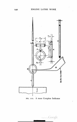
Colvin's treatment of this subject is notable for several reasons. He illustrates three different centering indicators, some of which might be made very simply. He demonstrates a real knowledge of the subject. Perhaps most importantly, he illustrates the use of a centering indicator with an "outboard" (if you will) reference point which is not a tailstock dead center. I believe that this is the only illustration of this method in the literature.
Each of the images above links to a larger PDF of the image/page. Here is the complete chapter on indicators from Colvin's book: colvin-test-indicators-and-their-use-chapter-in-colvin-1909-engine-lathe-work-google-udglAQAAMAAJ-mich.pdf Here, for reference and because everything Colvin wrote should be better known, is a local copy of the entire book: colvin-1ed-2imp-1909-engine-lathe-work-google-udglAQAAMAAJ-mich.pdf
Colvin, Fred H. Engine Lathe Work. First Edition, Second Impression. NY: McGraw-Hill Book Company, 1909.
Digitized by Google from the University of Michigan copy. Google ID: udglAQAAMAAJ
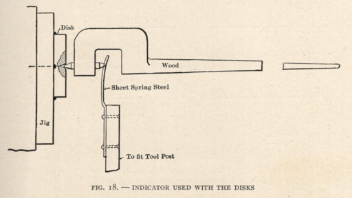
Goodrich and Stanley's Accurate Tool Work (1912) is a collection of very interesting material adapted primarily from The American Machinist. It has a section which discusses the use of toolmaker's disks for precision hole location when making drilling jigs in the lathe. (This method, which you won't find in more recent textbooks, involves locating using the center distances between disks and the triangulation of the centers of three disks in contact with each other.) In the context of this discussion, they propose the use of an indicator made of wood (for lightness). They do not describe its use.
Goodrich C. L. and F. A. Stanley. Accurate Tool Work. NY: McGraw-Hill Book Company, 1912.
Scanned by me from my copy. Public domain.
from Jones' Modern Toolmaking Methods (1915).
This material was recycled by The Industrial Press several times. The version above comes from:
Jones, Franklin D., ed. Modern Toolmaking Methods. NY: The Industrial Press, 1915.
Digitized by Google from the Univ. of Wisconsin copy. Google ID: oEJVAAAAMAAJ
Jones, Franklin D., ed. Gaging Tools and Methods. Machinery's Reference Series, No. 130. NY: The Industrial Press, 1914.
Digitized by Google from the Univ. of Wisconsin copy. Google ID: AmNGAAAAMAAJ.
An anonymous article in the September 1939 number of Popular Science describes, with measured drawings, the construction of a center indicator constructed around a ball bearing. The article contains no instructions at all for its use.
Anon. "Wiggling Indicator for Centering Irregular Work in the Lathe." Popular Science. Vol. 135, No. 3 (Sept. 1939): 167.
Viewable (but in copyright and not downloadable) via Google Books at https://books.google.com/books?id=7SwDAAAAMBAJ
In a 1971 article in Popular Mechanics, Walter Burton describes the construction and use of two centering indicators.
One uses a ball bearing captive between two flat springs. This version also includes an optional guide for restricting motion to a single plane (the horizontal/XZ plane).
The other uses a short double-ended rod from a mount point to the workpiece, with a ring to carry a long pointer. (This version is similar to the one shown in Colvin's Fig. 110 from Engine Work (1909), q.v.)
Burton's discussion is interesting with regard to the issue of alignment with a dead center in the tailstock. He acknowledges that "recommendations for using such center indicators call for aligning the pointer with the tailstock center" and that "this may involve careful adjusting of the position of the instrument in the carriage." But he never describes how to do this "careful adjustment."
He does, however, illustrate the use of an arbitrarily positioned pointer for using the indicator when it is not on the centerline of the lathe. (He uses a pointed soft aluminum wire held in a drill chuck in the tailstock, which is quite clever.)
Burton, Walter E. "Make a Center Indicator for Lathe Work." Popular Mechanics. Vol. 135, No. 5 (May 1971): 126-129, 174, 176.
Viewable (but in copyright and not downloadable) via Google Books at https://books.google.com/books?id=mdcDAAAAMBAJ
While I haven't yet finished my research into the origins of the machinist's instrument known as the "test indicator," I wouldn't be surprised to discover that the test indicator developed out of the center indicator when applied to other kinds of work.
James Hobart in 1907 describes and illustrates an "indicator" which is, in terms of construction, a lever-style center indicator as discussed here. But he discusses only its application to centering cylindrical work by application to the periphery of that work, as you would use a test indicator.
Hobart, James F. The Screw-Cutting Lathe. NY: McGraw Publishing Company, 1907.
Digitized by Google from the New York Public Library copy. Google ID: um0JAAAAIAAJ Here is an extract of just this page (also linked from the image above): hobart-1907-the-screw-cutting-lathe-pp72-74-google-um0JAAAAIAAJ-nypl.pdf
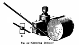
In The Americn Watchmake and Jeweler, a technical encyclopedia introduced in 1891 and reprinted several times (and sometimes copied under different titles), Henry Abbott illustrates a simple test indicator but calls it a "centering indicator." This appears on p. 73 of the 1891 edition; it is on p. 83 of the 1898 edition.
All of the material reprinted here is in the public domain.
The material in Popular Science and Popular Mechanics referenced here is in copyright; therefore it is not reprinted.
All portions of this document not noted otherwise are Copyright © 2021, 2022 by David M. MacMillan.
Circuitous Root is a Registered Trademark of David M. MacMillan.
This work is licensed under the Creative Commons "Attribution - ShareAlike" license, version 4.0 International. See http://creativecommons.org/licenses/by-sa/4.0/ for its terms.
Presented originally by Circuitous Root®