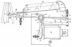
Parriss' rolling ball free pendulum impulsing device
(Image authorized for free dissemination by the Comptroller of Patents (UK))
The Rolling Ball Web
An Online Compendium of
Rolling Ball Sculptures, Clocks, Etc.
By David M. MacMillan et. al.
Click on photo to see the entire patent (1 image, approx 22.3k)
Parriss' rolling ball free pendulum impulsing device
(Image authorized for free dissemination by the Comptroller of Patents (UK))
There is no such thing as a free pendulum, because a pendulum can never be totally isolated from its environment. If it could, it's Q1 would be infinite and we would have perpetual motion. Freedom has always been an unattainable ideal, but the degree to which it has been approached is truly remarkable, so much so that the term free pendulum need hardly be regarded as a contradition in terms.
Philip Woodward. My Own Right Time. 82.
The clocks discussed in this section use rolling balls to assist the clock's oscillator. As it happens, each of the three cases discussed is an attempt to create a so-called "free pendulum" clock. In all pendulum clocks, the swing of the pendulum gradually decays due to various forms of friction. Pendulums are therefore periodically given more energy so that they may continue to swing; this additional energy is traditionally called an "impulse." In most clocks, the pendulum must do some clearly visible work in order to trigger the impulse. For example,
It is very difficult to conceive of a way in which an oscillator might receive its necessary impulses without in some way expending energy to signal for them. However, in the so-called "free pendulum" clocks epitomized by the famous Shortt or Synchronome-Shortt clock developed by William Hamilton Shortt with the assistance of Frank Hope-Jones and the Synchronome Company in the 1920s, this does seem to be the case. To understand how this happens, it is best not to delve into a drawing of a Shortt clock immediately. A Shortt clock is relatively complex in its details, moreso since Shortt was an exceptional engineer who detested brute-force solutions. Certain aspects of the Shortt clocks are more complex than they might be simply to produce what was in Shortt's mind a more elegant design. Instead, consider the schematic diagram below, which will be developed later into a more detailed presentation of the Shortt system.
A good drawing of the Shortt clock, noted as having been redrawn from a drawing by W. H. Shortt, appears in A. L. Rawlings' The Science of Clocks and Watches 3rd edition, 152. A very similar drawing, with more detailed explanatory material, appears in Pierre H. Boucheron's article "Just How Good Was the Shortt Clock?", 167. A different, but functionally similar diagram appears in Frank Hope-Jones' Electrical Timekeeping, 165. A good drawing of the "Synchronome switch" or Synchronome gravity remontoire escapement appears in Electrical Timekeeping, 88.

(In reading this drawing, first realize that the terms employed in it are not standard - I'm just making them up here because I am uncomfortable with the standard terms. The standard term for a clock such as this is not a "secondary-clock oscillator impulsing" clock, but instead a "free pendulum" clock. What I refer to as the "primary oscillator" is generally termed the "master pendulum"; my "secondary clock" is the "slave pendulum." I have chosen not to use the term "free pendulum" because this pendulum is not really "free." I have chosen to avoid the terms "master" and "slave" because these terms reflect a complex set of human interactions which are not in fact reflected in the mechanism here (though Woodward has an excellent description of the operation of such a clock in terms of a master and servant (My Own Right Time 83). If you wish to discuss these matters with others, please read Hope-Jones and Woodward and use the conventional terminology rather than the terminology used here.)
In the schematic diagram above, the secondary clock is a precision clock designed so as to deliberately run very slightly slow. (Boucheron estimates 1/20th of a second in 30 seconds.) The reason for its being deliberately adjusted to run slow will be given at the end of this explanation. In the actual Shortt clock, the secondary (slave) clock was essentially a modified Synchronome detached gravity escapement clock. The primary pendulum is just a pendulum.
Focus on the secondary clock. It's oscillator (here a pendulum, but in principle any oscillator) oscillates a fixed number of times and then triggers a signal. In the actual Shortt clock, this was a seconds-beating pendulum which completed 15 full (back and forth) oscillations in a 30 second period and then triggered a signal.

The diagram above illustrates the "impulse trigger" (my term) of the Shortt clock, which is essentially a Synchronome gravity escapement. Gravity arm G2 is normally held in place by a catch C and is out of the way. A "gathering click" gc (a short lever with a pawl on the end of it) is connected to the pendulum and rides on the count wheel W. The pendulum P2 is a "seconds-beating" pendulum, which means that each swing of the pendulum takes one second; a full oscillation of the pendulum thus takes two seconds. As the pendulum swings to the left, the gathering click gc slides over a tooth of the count wheel W. This wheel is restrained from moving counterclockwise by the restraining click rc. As the pendulum then moves from left to right, the gathering click gc catches one tooth of the count wheel W and pulls it to the right. Count wheel W has 15 teeth, so one full revolution of the count wheel takes 30 seconds. Every 30 seconds, a vane V attached to the count wheel unlocks the catch C. At this point in time, the pendulum P2 is swinging to the right, but is probably still left of center. The unlocking of catch C allows the gravity arm G2 to fall, and given the position of the pendulum the roller R on G2 falls onto the bracket B attached to the pendulum. This bracket is so constructed that its top face Bf1 is a curve concentric with the rotational axis of the pendulum. If the gravity arm falls on this face, no impulse is given to the pendulum until the pendulum swings far enough to the right that the roller R moves onto bracket face Bf2. Bf2 is so curved that the roller R and the gravity arm roll down it, delivering energy to the pendulum. At some point during the swing to the right, roller R falls off the bracket and is entirely clear of the pendulum. The gravity arm G2 continues to fall until it touches contact T2 on armature A2. This completes an electrical circuit, which energizes electromagnet M2. The electromagnet M2 pulls armature A2 towards it, which in turn pushes the gravity arm G2 back up where it is once again held in place by catch C.
Thus far, this mechanism has been identical to the standard Synchronome movement, and indeed insofar as it this mechanism involves the secondary clock it is identical. However, the electrical signal created by the closing of the contact T2 is used not only to energize electromagnet M2, but also as the signal to impulse the primary oscillator. Thus the two functions of 1) energizing the secondary clock's pendulum and 2) signalling that an impulse should be given to the primary oscillator are combined into one mechanism.
This signal is passed to an impulsing mechanism next to the primary oscillator ("master pendulum" in the Shortt). The primary and secondary oscillators will have been adjusted so that the impulse triggered by the secondary clock arrives at such a point in the movement of the primary oscillator that it adds energy to it.
If this were all there was to it, though, a problem would occur. The secondary clock is not perfect - no clock is perfect. So no matter how carefully adjusted the primary oscillator and secondary clock might be, in time the secondary clock would drift out of phase with the primary. Given enough time, the impulses triggered by the secondary clock would become so out of phase with the primary oscillator that they would take energy from it, causing the clock eventually to stop.
The cleverness of a Shortt-style clock (and of other clocks which preceded it, such as Rudd's) is that it manages to resynchronize the secondary clock to the primary oscillator without any apparent expenditure of energy by the primary oscillator. It is important to understand precisely how this was done, because the explanations conventionally given omit one factor which becomes important in, at least, the Parriss rolling ball variant.

The drawing above represents a simplified form of the impulsing device. (The actual impulsing arm and the suspension of the roller on the pendulum were more complex in the real Shortt clock, but the version here omits no detail necessary for the point to be made here.)
Rolling balls are appealling in this application because they transfer energy and information in one direction only. A ball rolling down an incline transfers energy and information to the object it may strike at the end, where a rod or gear train used in the same capacity could potentially transfer energy or information back to the originator. In this regard, these rolling balls resemble the stream of water in the Earl of Meath's clock. (Meath's clock is not really a "free pendulum" clock because the pendulum performs work on the deflector pallet.)
Lloyd (Dictionary 61-62) briefly describes a series of clocks created by Edwin Craig (Northern Ireland) which use two balls rolling down short planes to impulse a pendulum as it reaches dead center. The balls thus serve the purpose of isolating the pendulum from the escapement The description given is appropriate to the type of book in which it appears, but is too short to allow me to fully comprehend the design. This clock is currently in the Science Museum, London.
Turpin account
Electrical Timekeeping account
1 Q is a term from electrical engineering that may be employed in the analysis of resonators in any field. It is a dimensionless quantity which represents the "quality" of a resonator. Numerically, it is "the ratio of the peak restoring force to the peak damping force" (Woodward 11). Values of Q range from 100 or less for a mechanical watch to 100 million or more for an atomic clock. If all other factors are equal, higher Q translates into better timekeeping. However, all other factors are never equal, and the use of Q in mechanical horology has been subject to much contention.
Woodward, in My Own Right Time, provides an accessible account of Q. He also cites Estill Green, "The Story of Q." American Scientist. 43 (1955): 584-595. I have not yet read this source.
With the exception of any material noted as being in the public domain, the text, images, and encoding of this document are copyright © 1996-1998 by David M. MacMillan.
This document is licensed for private, noncommercial, nonprofit viewing by individuals on the World Wide Web. Any other use or copying, including but not limited to republication in printed or electronic media, modification or the creation of derivative works, and any use for profit, is prohibited.
This writing is distributed in the hope that it will be useful, but "as-is," without any warranty of any kind, expressed or implied; without even the implied warranty of merchantability or fitness for a particular purpose.
In no event will the author(s) or editor(s) of this document be liable to you or to any other party for damages, including any general, special, incidental or consequential damages arising out of your use of or inability to use this document or the information contained in it, even if you have been advised of the possibility of such damages.
In no event will the author(s) or editor(s) of this document be liable to you or to any other party for any injury, death, disfigurement, or other personal damage arising out of your use of or inability to use this document or the information contained in it, even if you have been advised of the possibility of such injury, death, disfigurement, or other personal damage.
All trademarks or registered trademarks used in this document are the properties of their respective owners and (with the possible exception of any marks owned by the author(s) or editor(s) of this document) are used here for purposes of identification only. A trademark catalog page lists the marks known to be used on these web pages. Please e-mail dmm@lemur.com if you believe that the recognition of a trademark has been overlooked.
Version
1.2, 1998/06/18.
Feedback to dmm@lemur.com
http://www.database.com/~lemur/rbc-assist.html
Go to the: