Parriss' rolling ball free pendulum impulsing device
(Image authorized for free dissemination by the Comptroller of Patents (UK))
The Rolling Ball Web
An Online Compendium of
Rolling Ball Sculptures, Clocks, Etc.
By David M. MacMillan et. al.
Click on image for a larger view (47.5k)
Parriss' rolling ball free pendulum impulsing device
(Image authorized for free dissemination by the Comptroller of Patents (UK))
Note: Some web browsers do not display images with full fidelity. For best image quality, save these images to temporary files and view them with an offline image viewing program. Please note that even when saved to files the licensing terms and the disclaimers stated in the Legal Matters section of this document still apply to these images.
WWW Technical Note: If you click on the image above, a larger view should appear in a new browser window, if your web browser supports the nonstandard feature I used to enable this behavior. If it does, then you can move or resize this window in a manner independent of the main window. When you are done with this new window, use your browser's "close" menu item in this window to close it (or simply close the windows itself using whatever method your operating system provides for closing windows). Please note that using your browser's "back" button in this new window may produce unpredictable results.
If your web browser does support this behavior, then I hope that this new image (actually a separate web page containing this new image) will simply replace the current page. If so, use your web browser's "back" button to return to the current page.
If something else happens, I'd be interested in knowing about it.
Application Date: Aug 7, 1944. No. 15005/44.
Complete Specification Left: Aug 2, 1945.
Complete Specification Accepted: May 9, 1947.
PROVISIONAL SPECIFICATION
Improvements in Clocks or Time Switches
I, ERNEST GOREGE PARRISS, a British Subject, of 106, Abbey Street, Nuneaton, in the County of Warwick, do hereby declare the nature of this invention to be as follows:--
This invention comprises improvement in clocks or time switches and has for its object to provide improved means for controlling the movement of the pendulum and thereby the clock mechanism or controlling the time switch.
According to this invention, the mechanism comprises a pivotally mounted inclined ball guide, an electro-magent, the armature of which carries an arm located beneath one end of the ball guide, the said arm and ball guide forming part of the magnet circuit, which circuit is closed when the guide is tipped by the passage of a ball, the consequential movement of the armature and its arm throwing the ball to its initial position.
As applied to a clock, the pendulum is provided with a guide on to which the ball falls on its way to the main ball guide and thereby imparts motion to the pendulum, the pendulum being of the free type and it does not perform any work other than the measurement of time.
As applied to a time switch, a circuit may be made or broken by the movement of the armature, the time being controlled by the time taken by the ball in traversing the mechanism.
The ball guide is pivotally mounted near its centre, the ball receiving end being slightly heavier than the ball delivery end, and adjustable stop being above the delivery end so that in the normal position, the ball guide is held against the stop, the guide being slightly inclined downwardly from the ball receiving end to the delivery end, so that the ball will slowly traverse the guide. This guide may be formed of two metal rails suitably spaced apart or, it may be a member of channel section. When the ball reaches the lower and delivery end, an electric circuit is completed for the purpose of returning the ball to its starting position.
Above the ball guide is a ball receiving member which is inclined in the opposite direction to the ball guide so that the ball travels down the receiving member on to an intermediate member and then down the ball guide.
Beneath the lower end of the ball guide is an electro magnet, preferably with a horizontal axis, and an armature moving in a vertical plane pivoted above the magnet and having a substantially horizontal arm beneath the lower end of the ball guide, so arranged that when the magnet is energised, the free end of the arm will receive a quick upward movement which is transmitted to the ball guide in such a manner that the ball is thrown upwardly and into the ball receiving member.
In order that the upwardly thrown ball may pass on to the ball receiving member, a guide is provided having a curved guide above it so that the ball is thrown up against this guide, and as this guide overlaps the ball receiving member, the ball is delivered to the said ball receiving member.
The armature forms part of the magnet circuit as also does that portion of the ball guide which is between the pivot and the delivery end, contact members which may be adjustable being carried by the free ends of the arm and guide. The circuit is normally open, but when a ball passes to the lower end of the guide, this end of the guide moves downwardly and completes the circuit which controls the armature which throws the ball upwardly in the manner previously described.
The return of the ball guide may be assisted or effected by a spring, deposed around its pivot which spring may also form part of the electric circuit.
Two balls are used, so arranged that when one has reached the limit of its travel, the other which is in the ball receiving member is released and passed to the ball guide. For this purposse the ball guide near its upper end is provided with a retaining mechanism including a part which overhangs the path of the ball in the ball receiving member, when the ball guide is its normal position, but is moved upwardly thereby releasing the ball when the ball guide is tipped in the manner previously explained.
As applied to a clock, the pendulum is provided with a ball transfer device which may convenientlyi consist of a guide member of similar construction to the ball guide. This transfer device is conveniently downwardly inclined when the pendulum is in its middle position and is so arranged as to form substantially a continuation of the ball guide when the pendulum is at one end of its stroke. An extremity of the ball receiving member is above the pendulum transfer member and the mechanism is so timed that a ball released from the ball receiving member falls on to the pendulum transfer member, motion being imparted to the pendulum, and the ball passes from this transfer member on to the ball guide.
When applied to a time switch it will be obvious that the working of the magnet circuit above referred to can be utilised either directly or through a relay controlled by any desired mechanism, the time being regulated by that taken by the ball in passing through the mechanism.
Dated this 27th day of July, 1944.
FORRESTER, KETLEY & CO.,
Chartered Patent Agents,
Central House,
75, New Street, Birmingham, 2, and
Jessel Chambers,
88/90, Chancery Lane, London, W.C.2
COMPLETE SPECIFICATION
Improvements in Clocks or Time Switches
I, ERNEST GEORGE PARRISS, a British Subject, of 106, Abbey Street, Nuneaton, in the County of Warwick, do hereby declare the nature of this invention and in what manner the same is to be performed, to be particularly described and ascertained in and by the following statement:--
This invention relates to clocks, or time switches, and is concerned with that kind of clock or time switch which includes a free pendulum, i.e. a pendulum which performs no work other than the measurement of time. The invention has for its object to provide new or improved mechanism for imparting the required energy to the pendulum so as to keep the pendulum in operation.
According to this invention the free pendulum of the clock or time switch is energised by mechanism comprising a displaceable ball, a moveable ball actuating member adapted to receive the ball and to be displaced by weight or momentum of the ball to operate a solenoid, an armature controlled by said solenoid adapted on said operation to be displaced to impart further movement to siad ball actuating member whereby the ball is thrown, means for guiding said thrown ball back to said actuating member to impart a further displacement thereto and means for transmitting motion from said ball to said pendulum to thereby maintain the pendulum energised.
The free pendulum may form part of a clock while as applied to a time switch a circuit may be made or broken by the movement of the electromagnet armature, the operation of the switch being controlled by the time taken by the ball in traversing the mechanism.
In order that my invention may be clearly understood and more readily carried into practice, I have appended hereto a drawing showing the mechanism aforesaid applied to controlling the movement of a clock pendulum.
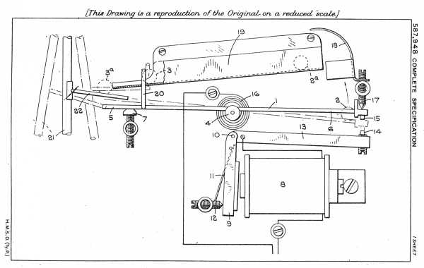
In the construction illustrated the moveable ball actuating member is indicated at 1 and is in the form of a track consisting of a pair laterally spaced metal rails, or a channel member, adapted to support a pair of balls (indicated at 2, 3) which follow one another along it in a manner hereinafter described.
The member 1 is pivotally mounted near its centre at 4, one end 5 thereof being slightly heavier than the other end 6 and cooperating with a stop screw or other abutment 7 which is so adjusted that the member 1, when in the normal position (indicated in full lines), is slightly inclined downwardly from the end 5, with the result that a ball admitted thereto at the latter end will slowly traverse the member 1 at a rate dependent upon its inclination.
Beneath the lower end 6 of the member 1 is an electromagnet 8, preferably disposed with its axis horizontal, which has associated therewith an armature 9 pivoted at 10 above the magenet 8 for movement in a vertical plane. This armature 9 is biassed away from the magent core by means of spring 11 and normally engages an adjustable abutment 12.
Operatively connected to the armature 9 at its pivoted end is a substantially horizontal arm 13 extending beneath the lower end 6 of member 1, the arrangement being such that, when the magnet 8 is energised, the free end of the arm 13 will be given a quick upward movement which is transmitted to the end 6 of the member 1.
The armature arm 13 forms part of the magnet circuit as also does that portion of the member 1 which is between the pivot 4 and the lower end 6, contact members 14, 15, which may be adjustable, being carried by the adjacent ends of the arm 13 and the member 1 respectively. The circuit is normally open, but when a ball passes to the lower or delivery end 6 of the member 1, the latter tips into the position indicated in broken lines, thus bringing the contacts 14, 15 together and completing the circuit.
In the drawing, the ball 2 is shown at the delivery end of the member 1 just at the moment when the magnet 8 is energized. The consequent upward movement of the arm 13 returns the member 1 violently to its initial position in contact with abutment 7.
This return movement of the track may be assisted or effected by a torsion spring 16 associated with the pivot 4, which spring may also form part of the magnet circuit. If desired, a further adjustable abutment 17 may be provided for engagement by the delivery end 6 of the member 1.
The movement of the track end 6 as above described throws the ball 2 upwardly against a curved deflector 18, which overlaps the upper end of an inclined runway or trough 19 disposed above member 1 and so arranged as to guide the ball back to the upper or receiving end 5 of the latter; whereupon such ball again traverses the member 1 to the delivery end 6 and the sequence of operations is repeated.
When two balls are employed as above mentioned, means are provided to ensure that one ball is always on the runway 19 whilst the other is always on the member 1.
As illustrated, until one ball reaches the delivery end 6 of the member 1 (i.e. is in the position indicated at 2) the other ball is retained at the lower end of the runway, in the position indicated at 3. Such retention is conventiently effected by a hooked arm 20 carried by the member 1 and overhanging the runway 19 wo as to obstruct escape of the ball 3 therefrom until moved upwardly by the tipping of the track consequent upon the other ball reaching the position 2.
When released the ball in the runway 19 leaves the latter, as indicated at 3a, simultaneously with entry of the other ball into the runway as shown at 2a.
Adjacent the upper end 5 of the member 1 is a clock pendulum 21 of the free type, i.e. a pendulum which performs no work ohter than the measurement of time, provided with a ball transfer member 22 which may be of similar construction to the member or formed as a tray. This transfer member 22 is conveniently downwardly inclined when the pendulum 21 is in its mid-position and is so arranged as to form substantially a continuation of the runway 19 when the pendulum is at one end of its stroke. The mechanism is so timed that a ball released (as at 3a) from the runway 19 passes directly on to the ball transfer member 22, which latter serves as an abutment so that motion is imparted to the pendulum 21, and as the pendulum carries the member 22 into an inclined position the ball passes therefrom on to the member 1.
Instead of pivotally mounting the member 1 it may be fixed and a separate auxiliary pivotally mounted member used which receives the ball after it has traversed the member 1, the electric circuit being closed by the pivotal movement of the auxiliary member operating and arranged in similar manner to the pivoted member.
When the mechanism is applied to a time switch, it will be obvious that the working of the magnet circuit above referred to can be utilized either directly or through a relay controlled by any desired mechanism, the operation of the switch being regulated by the time taken by the ball in passing through the mechanism.
Having now particularly described and ascertained the nature of my said invention and in what manner the same is to be performed, I declare that what I claim is:--
1. A clock or time switch including a free pendulum and mechanism adapted to energise said pendulum comprising a displaceable ball, a moveable ball actuating member adapted to receive the ball and to be displaced by the weight or momentum of the ball to operate a solenoid, and armature controlled by said solenoid adapted on said operation to be displaced to impart further movement to said ball actuating member whereby the ball is thrown, means for guiding said thrown ball back to said actuating member to impart a further displacement thereto and means for transmitting motion from said ball to said pendulum to thereby maintain the pendulum energised.
2. Mechanism for operating a free pendulum clock or time switch comprising an electric control circuit including an electro magnet and a pair of contacts, a displaceable ball, a pivoted ball actuating member, one of said contacts being associated with said member so as to pivot therewith, siad member being adapted to receive the ball and to be pivoted by the weight or momentum thereof to operate said contacts to actuate said electro magnet, an armature controlled by said electro magnet adapted on said actuation to be displaced to impart further movement to said ball actuating member whereby the ball is thrown upwardly, stationary abutment means for receiving said thrown ball and deflecting it to the upper end of an inclined member down which the ball can run freely and means for returning it to said ball actuating member, and means for imparting motion from said ball to said pendulum to thereby energise the same.
3. Apparatus according to claim 1 or 2, further characterised in that the pendulum carries a ball receiving member adapted to receive the moving ball after it has been thrown and thereby to impart energy to said pendulum, said ball receiving member being adapted also to transfer the ball to said ball actuating member.
4. Apparatus according to any of Claims 1 to 3, further characterised in that the ball actuating member is formed as a track normally inclined to the horizontal, pivoted intermediate its ends and spring urged into said inclined position along with member the ball is adapted to run, the ball being received at the upper end of the member and being thrown at the other end thereof.
5. Apparatus according to Claim 4, further characterised in that the upper end of the inclined ball actuating member is somewhat heavier than the lower end and normally engages a stop.
6. Apparatus according to any of Claims 1 to 5, wherein the armature of the electro magnet actuates an arm adapted to engage directly with the ball actuating member so as to displace the latter, such arm and the ball actuating member forming part of the electric circuit.
7. Apparatus according to Claim 6 and according to Claim 4 or 5, wherein the arm is disposed beneath the lower end of the inclined ball actuating member and carrying a contact adapted to co-operate with a second contact at the lower end of the said member.
8. Apparatus according to any of the preceding Claims, further characterised in that the means for guiding the thrown ball back to the ball actuating member comprise a curved guide disposed above the position at which the ball is thrown and an inclined runway leading from said guide to the ball actuating member, the guide and runway being stationary.
9. Apparatus according to any of Claims 4 to 8, wherein a pair of balls are provided, the mechanism including means whereby, when one ball reaches the lower end of the inclined ball actuating member, the other ball is admitted to the upper end of the latter.
10. Apparatus according to Claim 9, and wherein the means for returning the balls to the upper end of the said member includes an inclined runway on to which the balls are thrown, the ball actuating member being provided near its uppper end with a retaining member which normally obstructs the pasage of a ball on the adjacent part of the inclined runway and which is moved to an inoperative position so as to release a ball from the latter whenever the ball actuating member is tipped by the passage down it of the second ball.
11. Mechanism for energising a free pendulum clock constructed substantially as described with reference to and, as shown in, the accompanying drawings. [the patent contains only one drawing - DMM]
Dated the 25th day of July, 1945.
FORRESTER, KETLEY & CO.,
Chartered Patent Agents,
Central House,
75, New Street, Birmingham, 2, and
Jessel Chambers,
88/90, Chancery Lane, London, W. C. 2.
Leamington Spa: Printed for His Majesty's Stationery Office, by the Courier Press. - 1947. Published at The Patent Office, 25, Southampton Buildings, London, W. C. 2, from which copies, price 1s. 0d. each (inland) 1s. 1d. (abroad) may be obtained.
[Thanks to James Nye for his assistance in obtaining a copy of this patent.]
A Note on UK patents and UK Crown Copyright: The United Kingdom has the curious concept of "Crown Copyright" whereby the state asserts copyright in public documents. The UK Public Records Office notes that Crown Copyright for documents such as patents published before August 1, 1989 "expires 50 years from the end of the calendar year of first publication." It is not clear to me whether, applied to Parriss' patent (where the application was made in 1944, the specification left in 1945, and the specification accepted in 1947) whether this would mean that copyright would expire at the end of 1994, '94, '96, '97, or '98. Fortunately, this question is irrelevant. Section 47(3) of the UK Copyright, Designs and Patents Act of 1988 specifies that the "appropriate person" can authorize the dissemination of documents of "general scientific, technical, commercial or economic interest" without copyright infringement. In the case of UK patents, the appropriate person is the Comptroller of Patents, who has indeed authorized this (Official Journal of Patents, 6 March 1991). Put simply, there is no restriction on copying UK patents in, at least, a noncommercial context such as the present one.
Thanks to Simon Allen for his assistance in resolving this question.
With the exception the text and images of this patent itself, as noted above, and of any material noted as being in the public domain, the text, and encoding of this document are copyright © 1998 by David M. MacMillan.
This document is licensed for private, noncommercial, nonprofit viewing by individuals on the World Wide Web. Any other use or copying, including but not limited to republication in printed or electronic media, modification or the creation of derivative works, and any use for profit, is prohibited.
This writing is distributed in the hope that it will be useful, but "as-is," without any warranty of any kind, expressed or implied; without even the implied warranty of merchantability or fitness for a particular purpose.
In no event will the author(s) or editor(s) of this document be liable to you or to any other party for damages, including any general, special, incidental or consequential damages arising out of your use of or inability to use this document or the information contained in it, even if you have been advised of the possibility of such damages.
In no event will the author(s) or editor(s) of this document be liable to you or to any other party for any injury, death, disfigurement, or other personal damage arising out of your use of or inability to use this document or the information contained in it, even if you have been advised of the possibility of such injury, death, disfigurement, or other personal damage.
All trademarks or registered trademarks used in this document are the properties of their respective owners and (with the possible exception of any marks owned by the author(s) or editor(s) of this document) are used here for purposes of identification only. A trademark catalog page lists the marks known to be used on these web pages. Please e-mail dmm@lemur.com if you believe that the recognition of a trademark has been overlooked.
Version
1.2, 1998/06/19.
Feedback to dmm@lemur.com
http://www.database.com/~lemur/rbc-parriss-patent.html
Go to the: