DMM Varkon® Tutorial
A Beginner's Guide to the Varkon
Parametric Modeling and CAD Application Development System
By David M. MacMillan
Varkon coordinate systems are two or three dimensional Cartesian systems consisting of an X, a Y, and, if the coordinate system is three-dimensional, a Z axis. Three-dimensional coordinate systems are "right-handed." (See the Geometry Center's Geometry Formulas and Facts for an explanation of right-handedness in 3D coordinate systems.) The origin of any coordinate system is a (0, 0, 0) for that system.
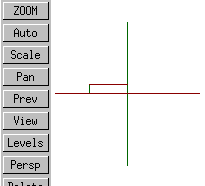
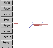
Since the Varkon system imposes no fixed set of views on the model (as some CAD systems do by laying out "first projection" or "third projection" viewing arrangements), it does not in general make sense to say that a particular axis is in a particular orientation relative to the screen. However, it is useful to see how an unrotated coordinate system appears in each of the standard "8 views" available in a default Varkon user interface.
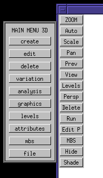
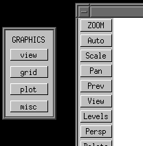
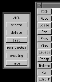
To enable these "8 views" using the standard Varkon menus, first go to the "MAIN MENU 3D". Then click on the "graphics" button. This brings up the "GRAPHICS" menu. Then click on the "view" button. This brings up the "VIEW" menu.
 |
 |
 |
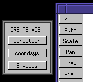
Then click on the "create" button. This brings up the "CREATE VIEW" menu. Finally, within the "CREATE VIEW" menu click on "8 views." Nothing will appear to happen. Use the right mouse button to return out of this nest of menu clicks.
Back at the drawing window, click on the "View" button.
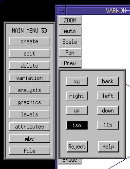
This displays the eight available views. For now, click on the "iso" view (which stands for ISOmetric, not the International Organziation for Standardization).
 |
 |
To visualize the coordinate system, we'll use the MBS module defined below. This is a GLOBAL module, so it uses whatever the current global coordinate system is (more on that later). It draws three lines, one for each axis. Red is used for the X axis, Green for the Y, and Blue for the Z. There is no good reason for this coloring, other than the fact that "RGB" is in the same order as "XYZ." (Unfortunately, text is not available in 3D Geometry mode, so we can't simply label these axes.)
! vcl.mbs Visible Coordinate Lines
!
! Draw 3 axes to illustrate a coordinate system
!
! X = red, Y = green, Z = blue
! (because I'm used to "RGB" in that order and "XYZ" in that order)
global geometry module vcl(
float delta; ! half-width of the axis line
float axisthickness; ! thickness of the axis lines
int linetype ! LFONT
);
vector xstart, xstop;
vector ystart, ystop;
vector zstart, zstop;
beginmodule
mode_basic (); ! probably redundant; force to BASIC coordinate system
! draw a visible X axis from negative to positive
xstart := vec (-delta, 0, 0);
xstop := vec ( delta, 0, 0);
lin_free(#1, xstart, xstop: PEN=2, WIDTH=axisthickness, LFONT=linetype);
! draw a visible Y axis from negative to positive
ystart := vec (0, -delta, 0);
ystop := vec (0, delta, 0);
lin_free(#2, ystart, ystop: PEN=3, WIDTH=axisthickness, LFONT=linetype);
! draw a visible Z axis from negative to positive
zstart := vec (0, 0, -delta);
zstop := vec (0, 0, delta);
lin_free(#3, zstart, zstop:PEN=4, WIDTH=axisthickness, LFONT=linetype);
endmodule
Using this vcl module, we can write an active module which calls it:
BASIC GEOMETRY MODULE test3d();
BEGINMODULE
part(#1,vclb(15, 0, 1));
ENDMODULE
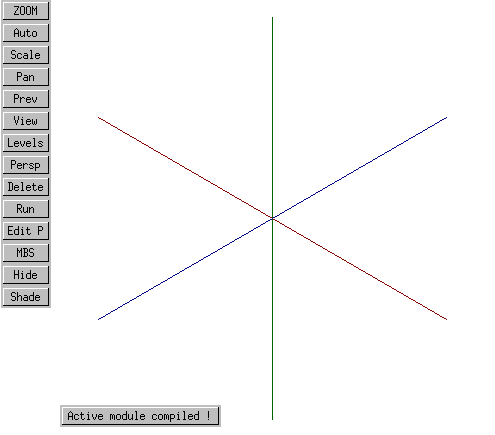
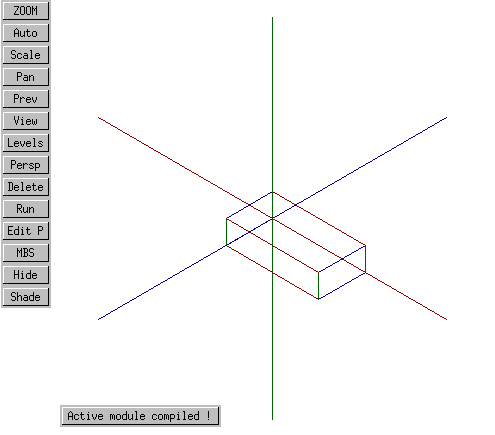
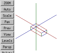
X is red, Y is green, Z is blue. Still, it's not clear which directions are positive and negative on these axes (does Z, for instance, go "in" or "out"?) To make this clear, let's use the MBS routine below to draw a box in the first quadrant. All points within this box are greater than or equal to zero.
! box1q.MBS
!
! Draw a box in the first quadrant
!
! Use the same coloring for the lines defining the box as is used for
! demonstration axes in vcl.MBS:
! X = red, Y = green, Z = blue (RGB == XYZ)
!
global geometry module box1q(
float x;
float y;
float z
);
vector lbb; ! left back bottom; origin
vector lbt; ! left back top
vector lft; ! left front top
vector lfb; ! left front bottom
vector rbb; ! right back bottom
vector rbt; ! right back top
vector rft; ! right front top
vector rfb; ! right front bottom
beginmodule
lbb := vec (0, 0, 0);
lbt := vec (0, y, 0);
lft := vec (0, y, z);
lfb := vec (0, 0, z);
lin_free (#1, lfb, lbb: PEN=4);
lin_free (#2, lft, lbt: PEN=4);
lin_free (#3, lfb, lft: PEN=3);
lin_free (#4, lbb, lbt: PEN=3);
rbb := vec (x, 0, 0);
rbt := vec (x, y, 0);
rft := vec (x, y, z);
rfb := vec (x, 0, z);
lin_free (#5, rfb, rbb: PEN=4);
lin_free (#6, rft, rbt: PEN=4);
lin_free (#7, rfb, rft: PEN=3);
lin_free (#8, rbb, rbt: PEN=3);
lin_free (#9, lbb, rbb: PEN=2);
lin_free (#10, lfb, rfb: PEN=2);
lin_free (#11, lbt, rbt: PEN=2);
lin_free (#12, lft, rft: PEN=2);
endmodule
We can instantiate this first-quadrant box by modifying the active module so that it contains the following:
BASIC GEOMETRY MODULE test3d();
BEGINMODULE
part(#1,vclb(15, 0, 1));
part(#2,box1q(8, 2, 4));
ENDMODULE
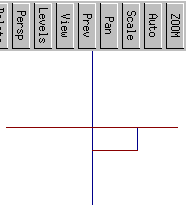 down(from above) |
||
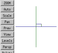 left |
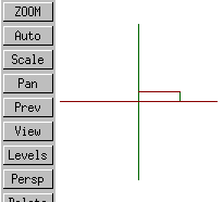 xy |
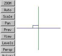 right |
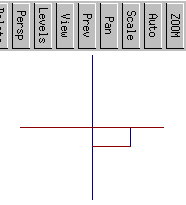 up (from below) |
||
 isometric |
 back |
 115 |
The short of it is that in Varkon's isometric projection X increases to the right, Y increases up, and Z points more or less out of the screen.
With the exception of any material noted as being in the public domain, the text, images, and encoding of this document are copyright © 1998 by David M. MacMillan.
The author has no relationship with Microform AB, and this Tutorial is neither a product of nor endorsed by Microform AB.
"Varkon" is a registered trademark of Microform AB, Sweden.
This document is licensed for private, noncommercial, nonprofit viewing by individuals on the World Wide Web. Any other use or copying, including but not limited to republication in printed or electronic media, modification or the creation of derivative works, and any use for profit, is prohibited.
This writing is distributed in the hope that it will be useful, but "as-is," without any warranty of any kind, expressed or implied; without even the implied warranty of merchantability or fitness for a particular purpose.
In no event will the author(s) or editor(s) of this document be liable to you or to any other party for damages, including any general, special, incidental or consequential damages arising out of your use of or inability to use this document or the information contained in it, even if you have been advised of the possibility of such damages.
In no event will the author(s) or editor(s) of this document be liable to you or to any other party for any injury, death, disfigurement, or other personal damage arising out of your use of or inability to use this document or the information contained in it, even if you have been advised of the possibility of such injury, death, disfigurement, or other personal damage.
All trademarks or registered trademarks used in this document are the properties of their respective owners and (with the possible exception of any marks owned by the author(s) or editor(s) of this document) are used here for purposes of identification only. A trademark catalog page lists the marks known to be used on these web pages. Please e-mail dmm@lemur.com if you believe that the recognition of a trademark has been overlooked.
Version
1.5, 1998/06/17.
Feedback to dmm@lemur.com
http://www.database.com/~lemur/vk-coordvis.html
Go to the: