This Journal entry describes in general terms (not installation-level details) the decisions I came to for handling the electrical power to the Barth. It also reviews briefly the history of the motive and heating power for the machine; without knowing this history, nothing makes sense. (But it isn't a full analysis of the ex-ATF electrical system. That will be done in one of the conservation Reports.)
Issues relating to electrical power of ex-industrial machinery in the home shop have been a part of my life for two decades now. I've discussed them with many people. What I find fascinating is that this is an area which goes beyond Strong Opinions and becomes a matter of Truth. Every person I talk to seems simply to know that they have figured out the One True Way in which this should be done, and that all other ways are without merit. No one seems particularly shy about conveying their insights. Curiously, each of these One True Ways is different.
This has turned out to be a rather long journal entry. Its length directly reflects the time spent working through these matters. There are a lot of possibilities, and it all requires a fair bit of background knowledge in non-typographical matters. It may seem like a long writeup here, but it's short compared to the research that went into it.
It is ironic that the machine's electrical systems are now the first things about it that must be attended to. It began without any electricity at all.
When it was designed, over a century ago, this machine was powered by leather belts running from an overhead or underfloor lineshaft (both are attested in ATF practice). These belts ran to the large stepped pulley just inboard of the flywheel. The pot was gas-fired, not electric.
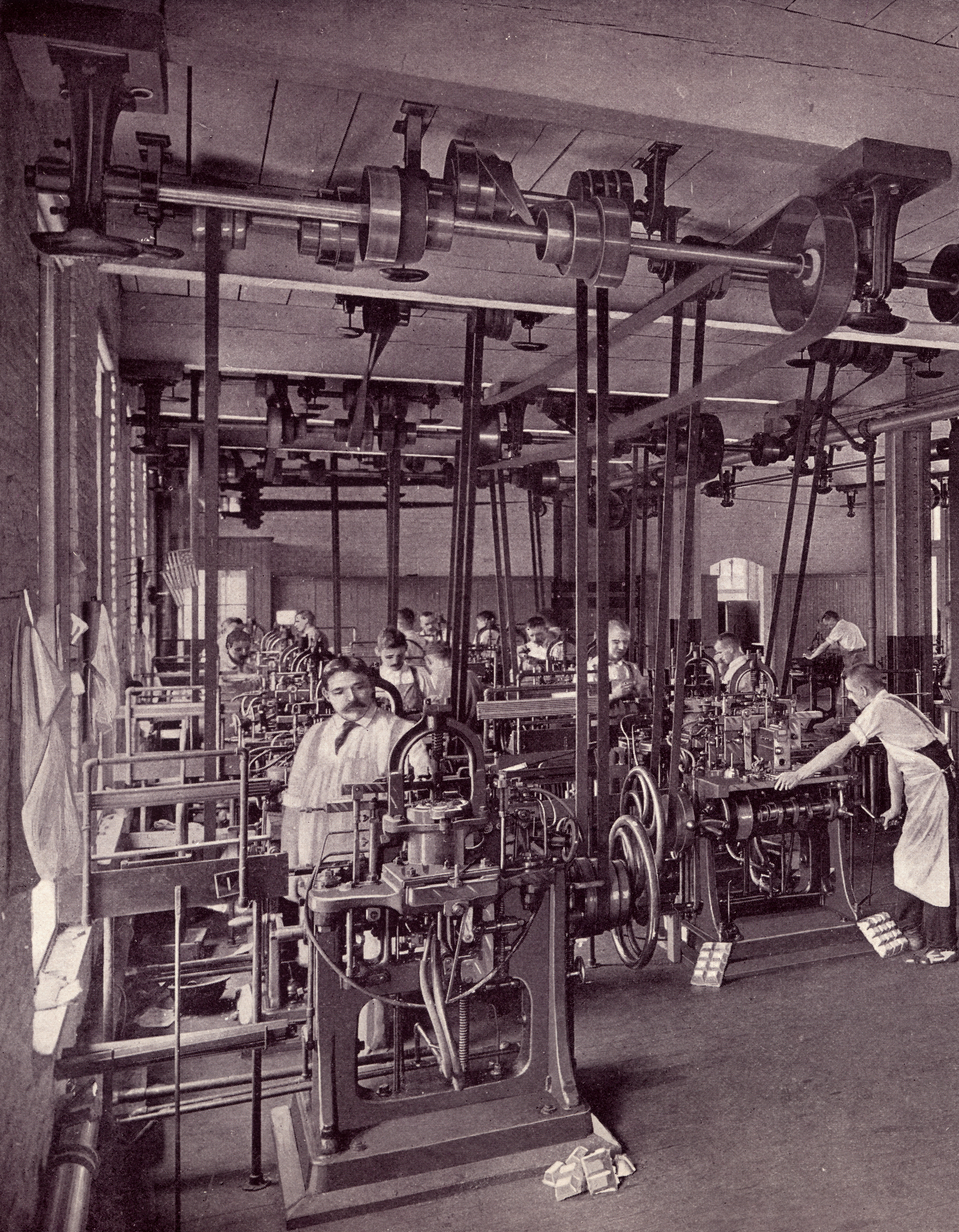
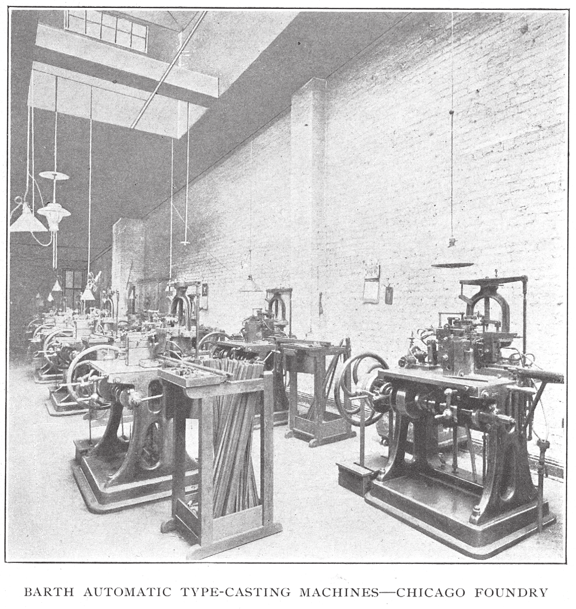
The photograph below left shows smaller Barths driven from an overhead shaft at the Philadelphia foundry of American Type Founders Company (ATF's Foundry 'C', formerly MacKellar, Smiths & Jordan). It appears in the 1896 book One Hundred Years , published by this branch as if it still was MSJ. The photograph below right shows Barths driven from an underfloor shaft at the Chicago foundry of ATF (ATF's Foundry 'E', formed from the merger of Marder, Luse with the Cleveland Type Foundry). It appears in ATF's 1902 promotional book American Type Founders Company: Its Business and Resources Illustrated. In both photographs the pots are gas-fired.
(The photos above link to 2048 pixel wide versions of the first image. Here is a 1200 dpi version: mackellar-smiths-jordan-1896-1200rgb-0062-centered-partial-automatic-casting-department-crop-barths-on-overhead-shaft-7557x9713.jpg)
Over a period of time, circa 1900, the driving power was changed to an electric motor. Photographs of Barth casters in ATF's 1902 promotional book American Type Founders Company: Its Business and Resources Illustrated show the machines in at least one ATF foundry (Cincinnati) with motors and at at least two other (Chicago and New York) with belts. This was a very large motor, possibly custom-designed, mounted onto the back of the machine. It contained, integrally, a large reduction drive. This drove a large stepped pulley on the left side (port side) of the machine. A leather belt then carried power to the original stepped pulley on the front of the machine. These two pulleys were stepped in opposite directions for speed control. Curiously, however, at least on this 60 point machine they were so constructed that the belt lengths necessary for each step weren't the same. (This is, yes, very strange. I've measured carefully.)
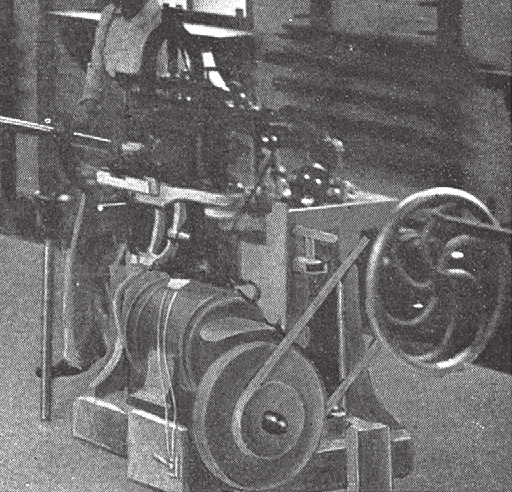
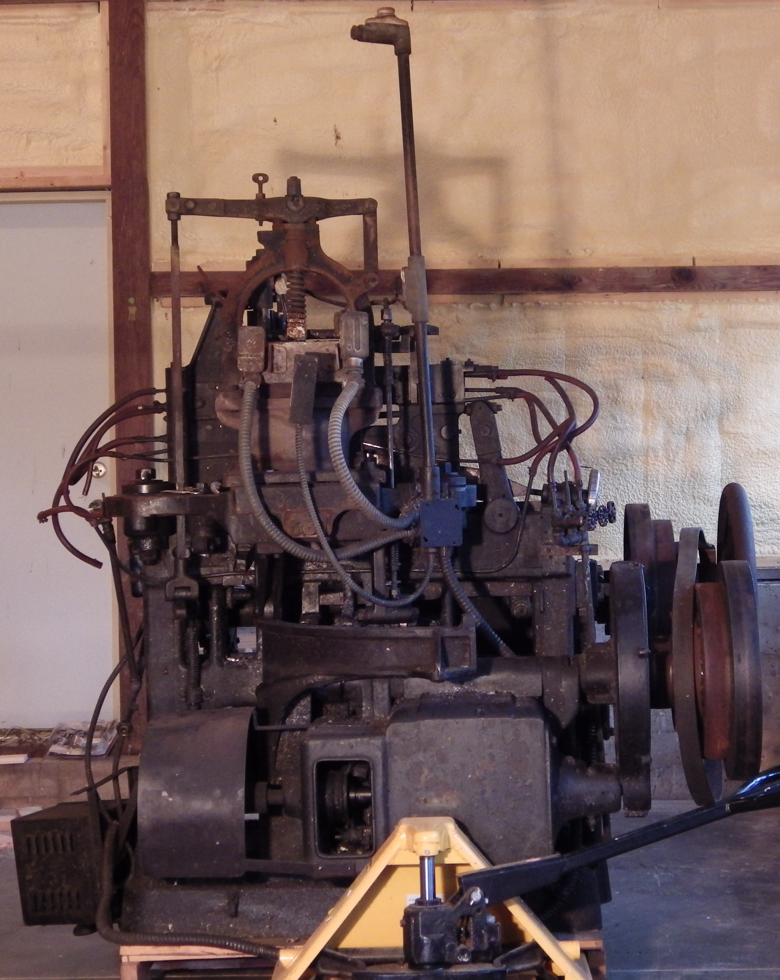
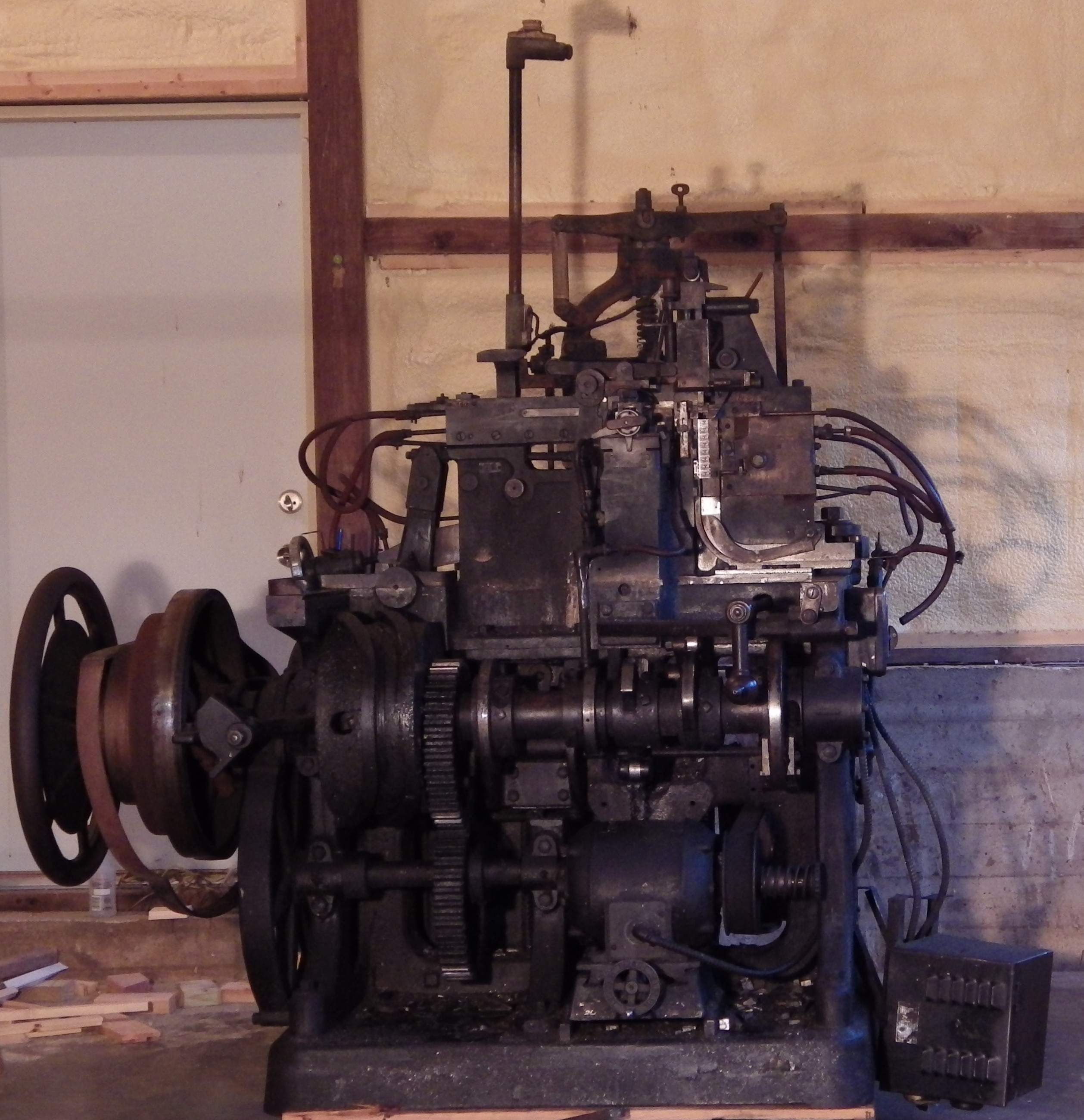
At left below is a smaller Barth caster at the Cincinnati foundry of ATF (Foundry 'D') as shown in American Type Founders Company: Its Business and Resources Illustrated (1902) At right below is a general view of the 60 pt Barth taken in 2014 just as it was coming in to my shop (hence the pallet jack). The motor is the large square box at the lower part of the machine, partly covered by the yellow pallet jack.
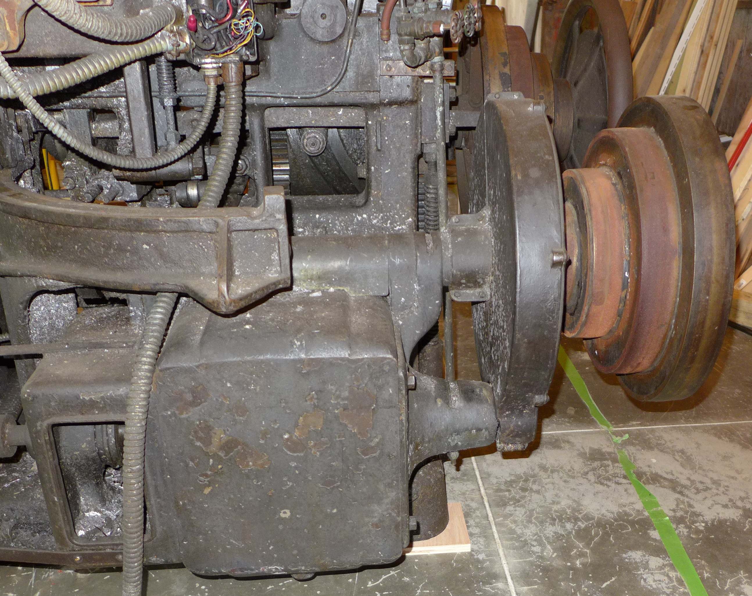
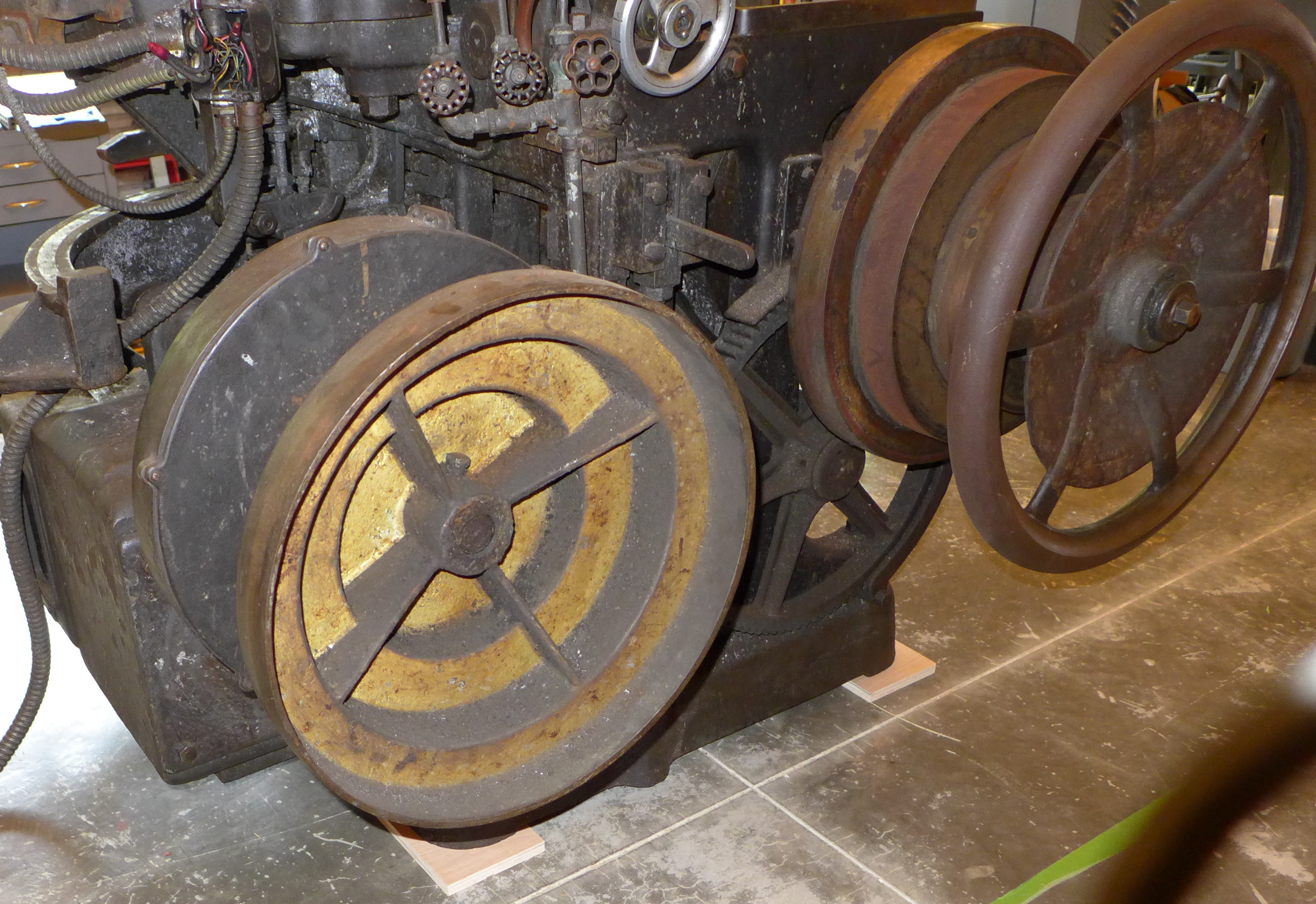
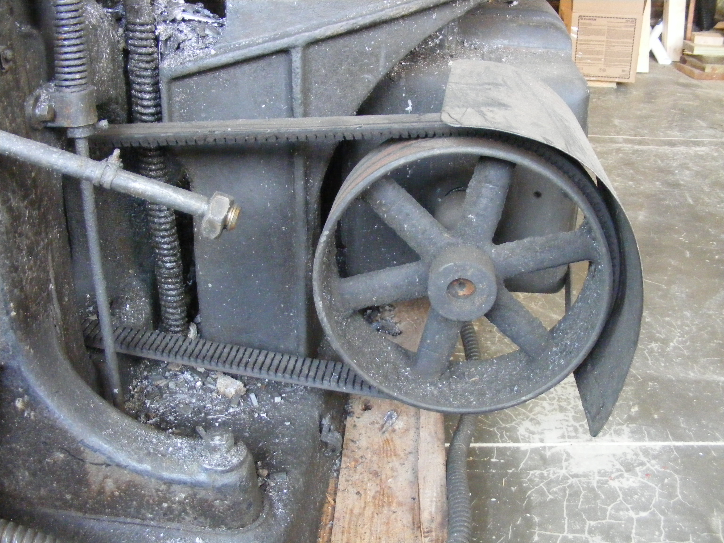
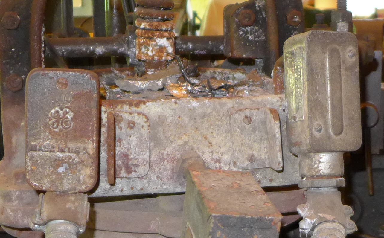
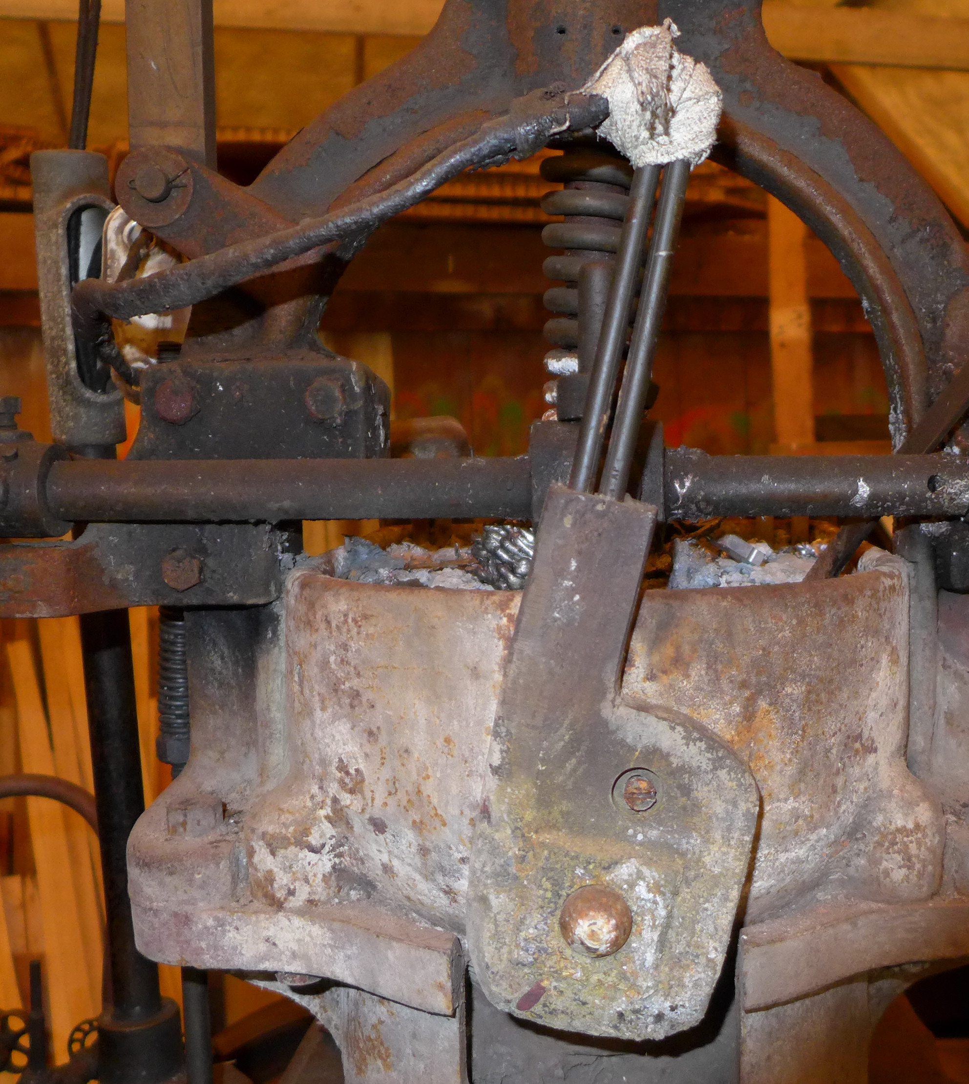
Here are closer views of the remains of the original motor (yes, that big squarish box was once an electric motor), the reduction gear (the round housing to the right of the motor) and the two big stepped pulleys (but the leather belt between them is not shown).
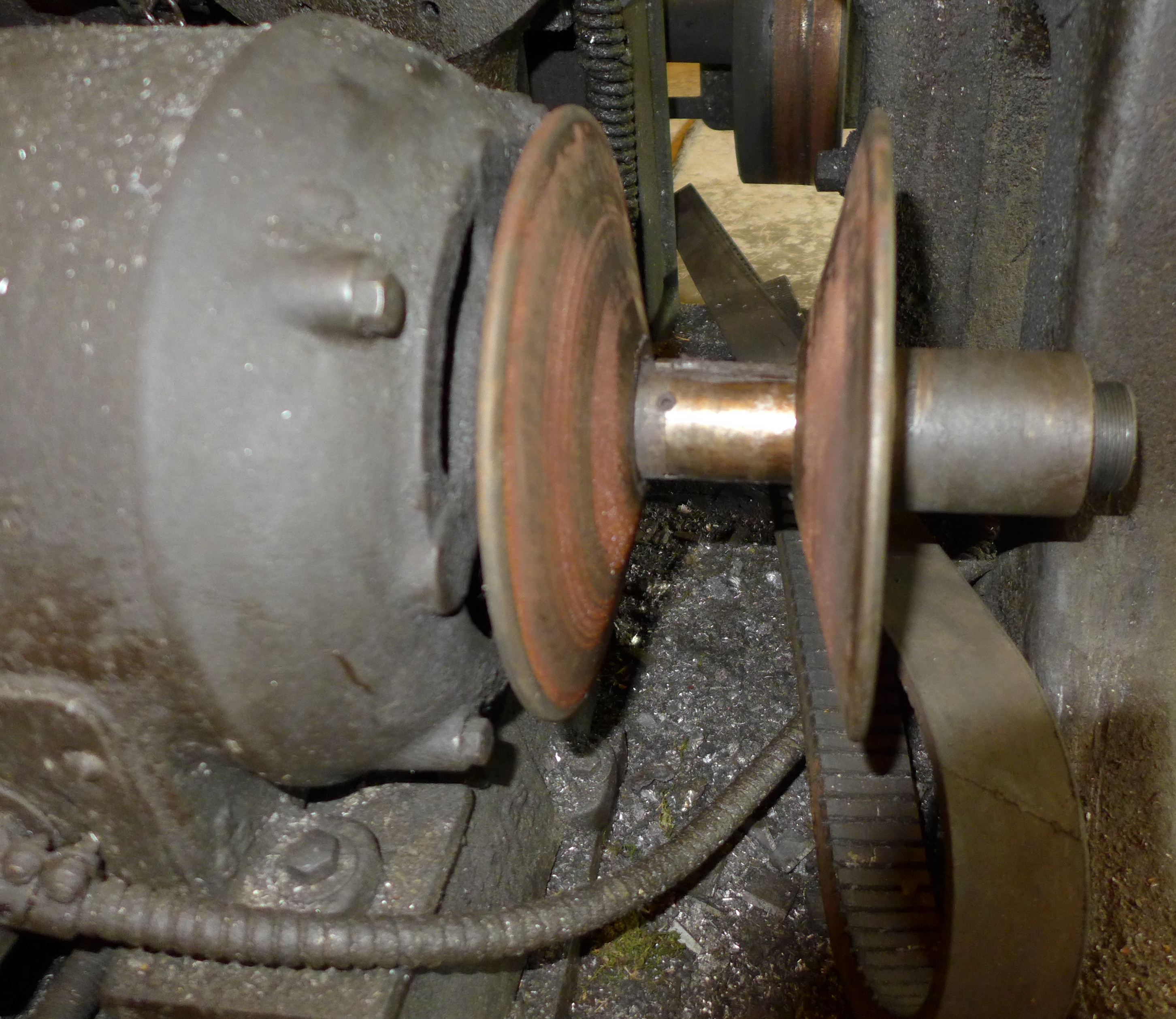
At some point before the mid-1940s 1 this original electrification of the power drive was abandoned, but many of its components were retained. The motor casing, reduction drive, and stepped pulley were kept in place. The rotating parts of the motor were removed and replaced by a simple shaft running through the original motor box and now extending outwards toward the right side of the machine (the right side as seen from the front; machine-right; starboard). On this shaft, ATF mounted a new flat-belt pulley.
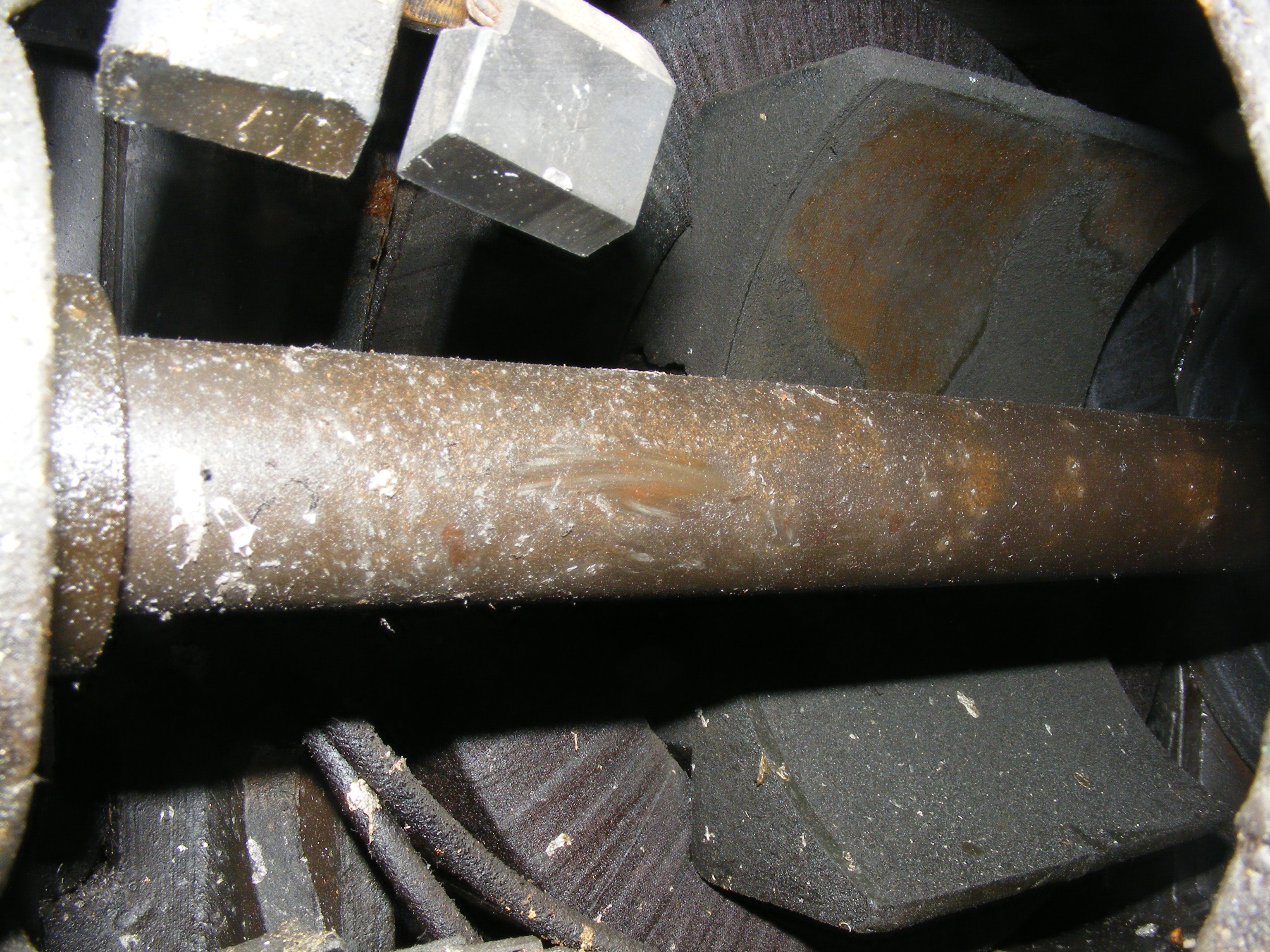
The photo below right shows the inside of the original motor with its static components still in place but its rotating components gone. Below right is the pulley that was added. This is a pulley for a flat belt, but the belt running to it is not an ordinary flat-belt.
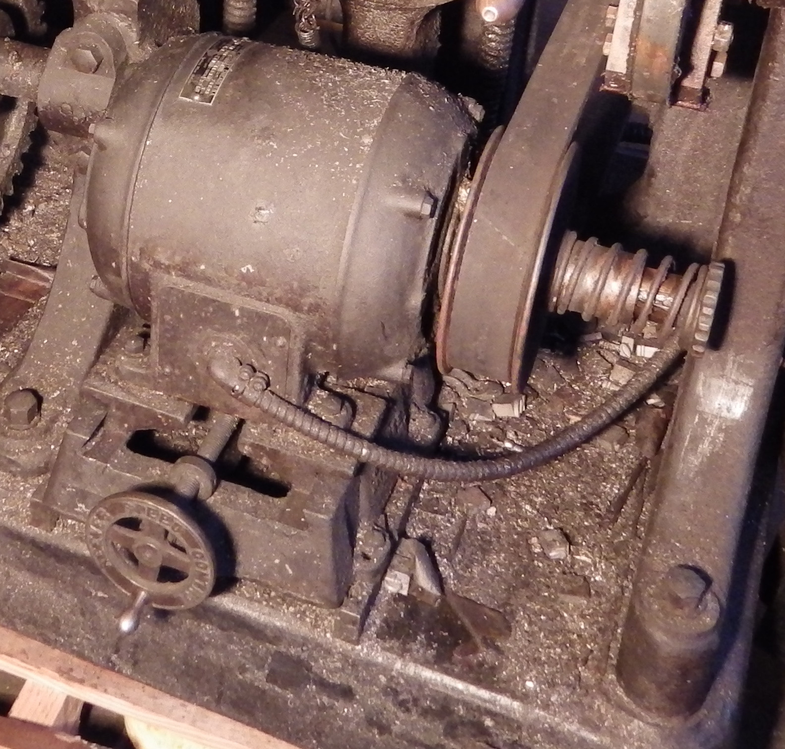
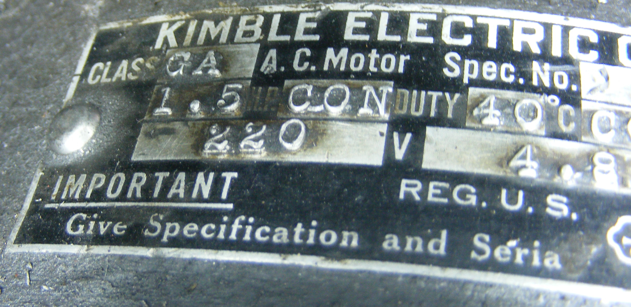
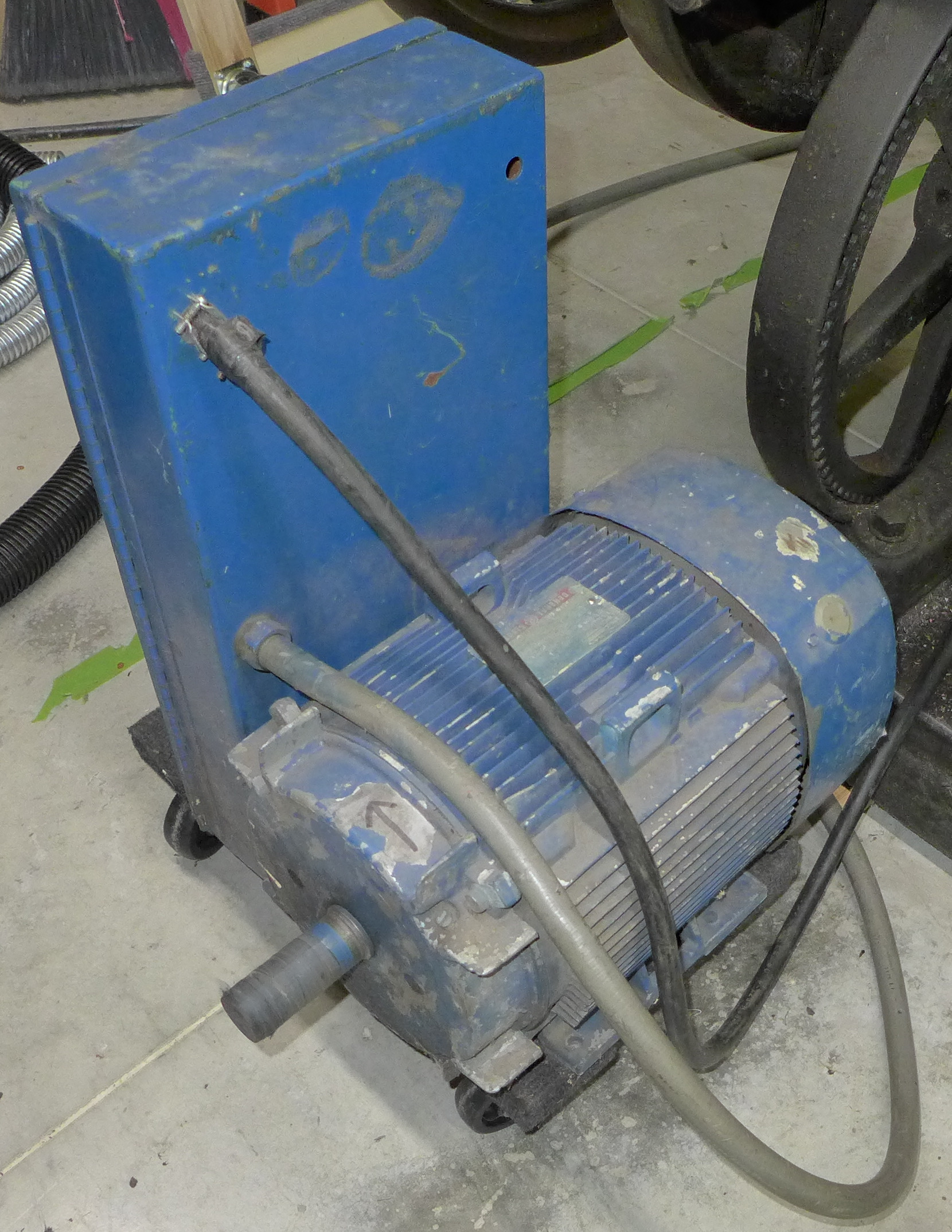
At the front of the machine, to its lower right, they installed a standard industrial motor. It is 1.5 HP, 1140 RPM, and three-phase 220V.
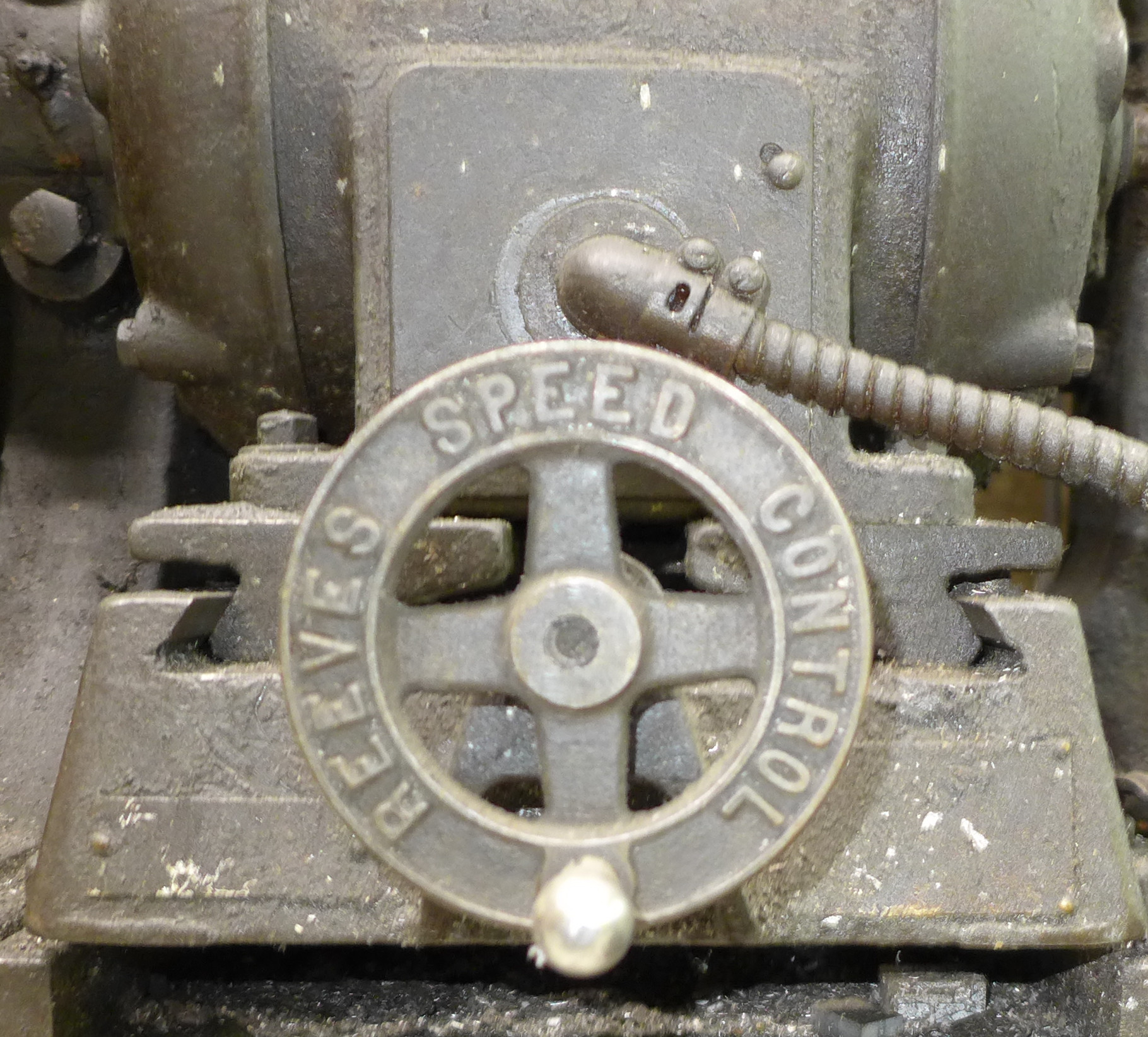
This motor was made by Kimble. Although Kimble was noted for their variable-speed motors, it is a single-speed motor. But they did install it with a Reeves variable-speed drive which employs a variable-diameter conical pulley. I haven't yet had experience running this, but it appears to vary the drive speed based on the tension on the belt. They V-pulley is spring-loaded. More tension on the belt (caused by moving the motor further forward) would pull it deeper into the pulley (forcing the pulley halves further apart) and reduce the speed (because the effective diameter of the pulley is reduced.
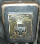
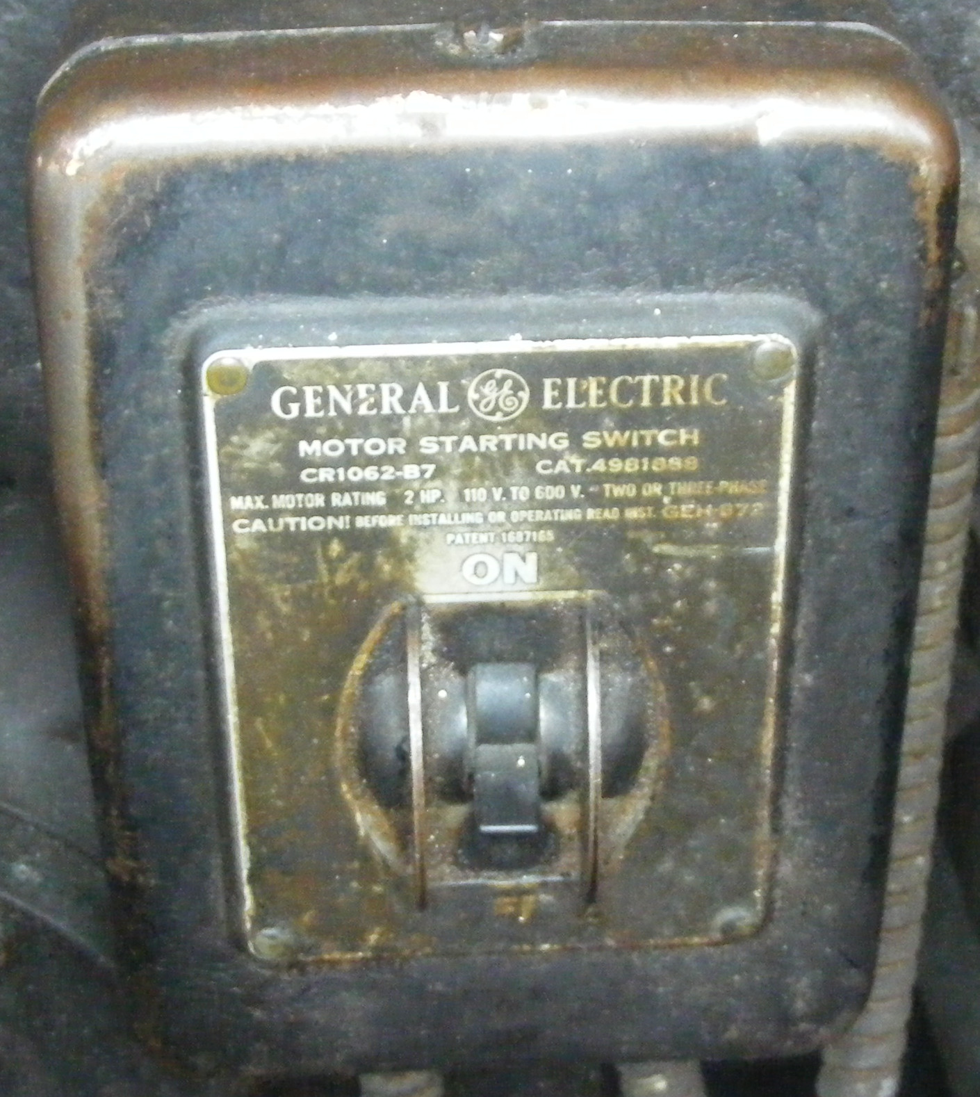
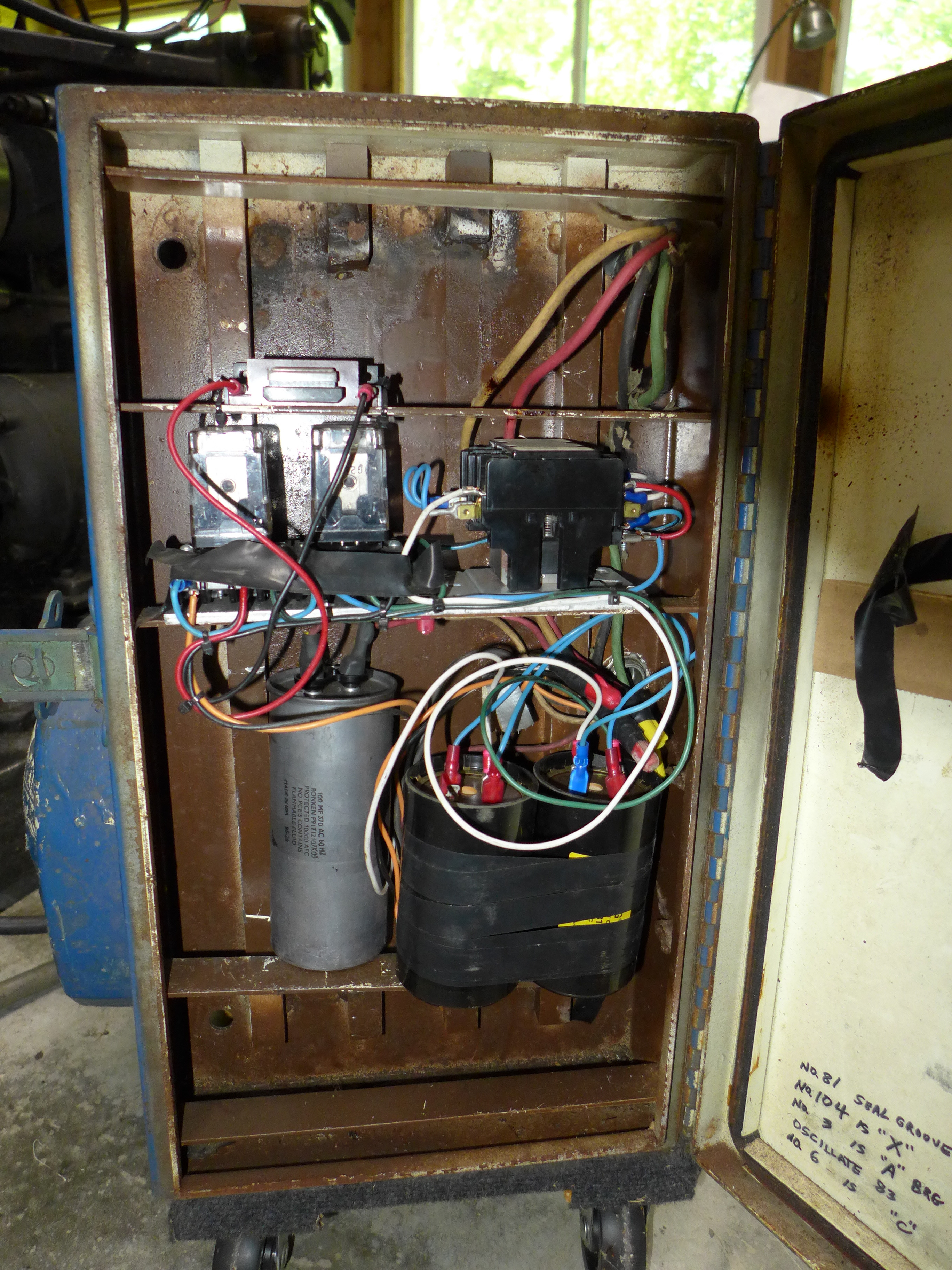
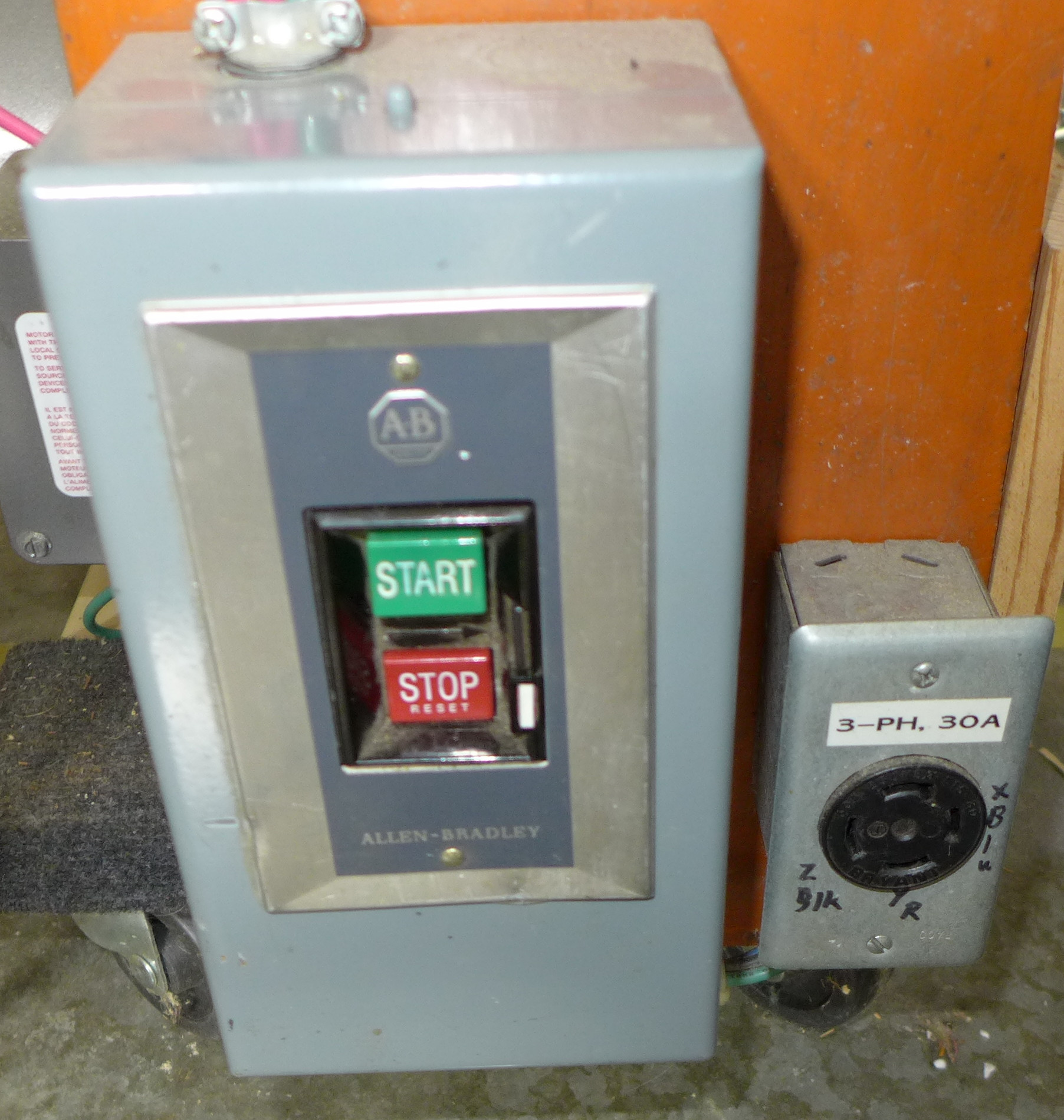
Electrically, the motor is controlled by a General Electric GE CR1062-B7 Manual Motor Starter switch. This switch has GE 81D-128 overload "heaters" on only two of the three lines. (A motor starter "heater" is not a heating unit at all, but rather a heat-actuated safety device which trips when an overcurrent condition produces too much heat.) I'm pretty sure that having heaters on only two of the three lines would not meet today's standards.
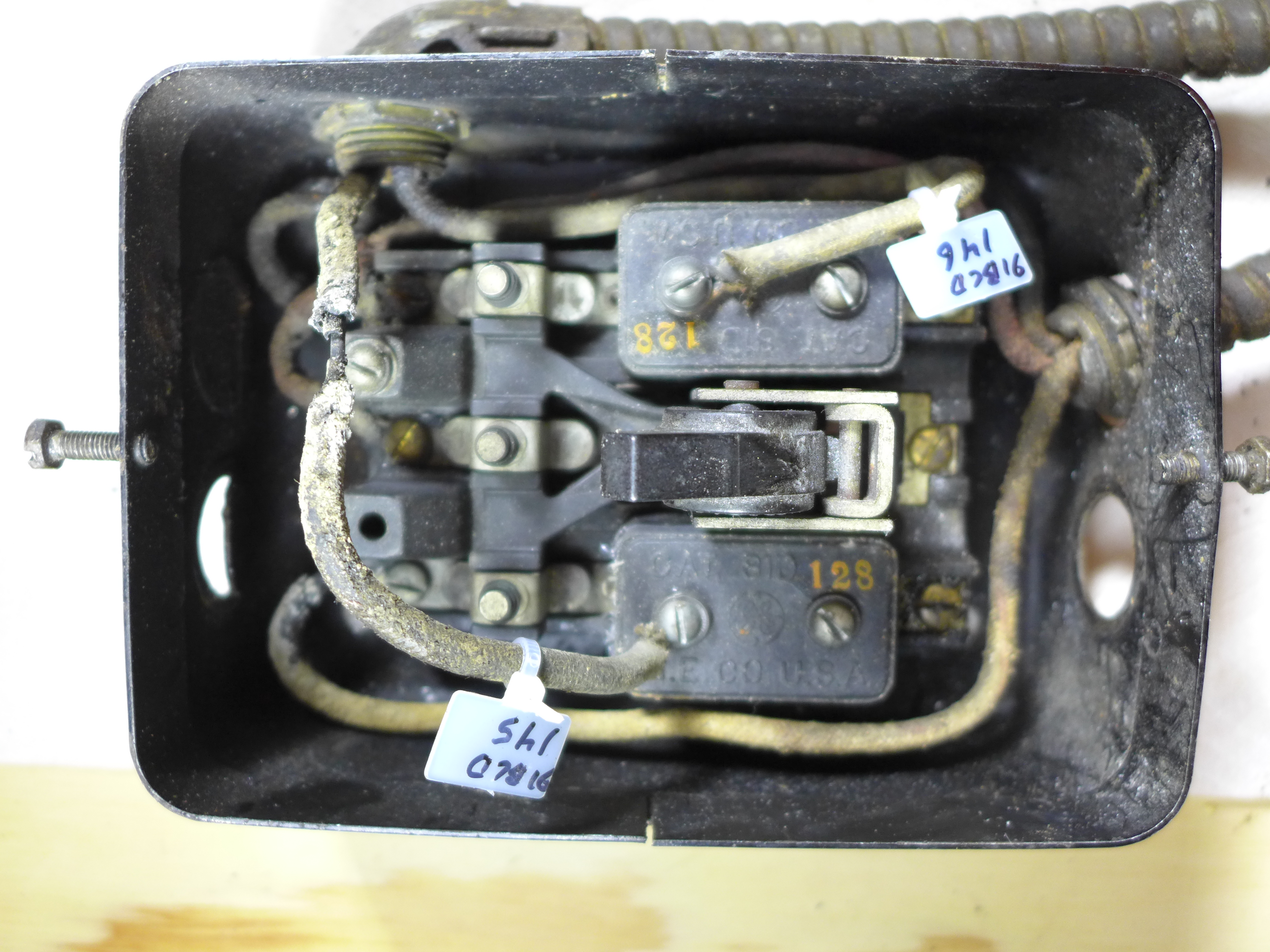
Also, and most confusingly, the power supply to the Nipple Heater is wired to screws which happen to be on each of the Motor Starter Heaters. (Wiring one kind of Heater to another completely unrelated kind of "Heater" doesn't make the life of a technical writer any easier.) You can see this in the photo below right (the Nipple Heater power lines are tagged with cable markers that I added). This photo also shows how the wire insulation had simply crumbled away in one part. This wire was pressed up against the inside of the motor switch plate and the machine was not grounded.
In 2015, I did a rough hand-held camera video walkaround of this drive system. It's on Youtube at https://www.youtube.com/watch?v=FfsZfqG4x0E
Rube Goldberg and Heath Robinson working together couldn't have devised a more convoluted drive system.
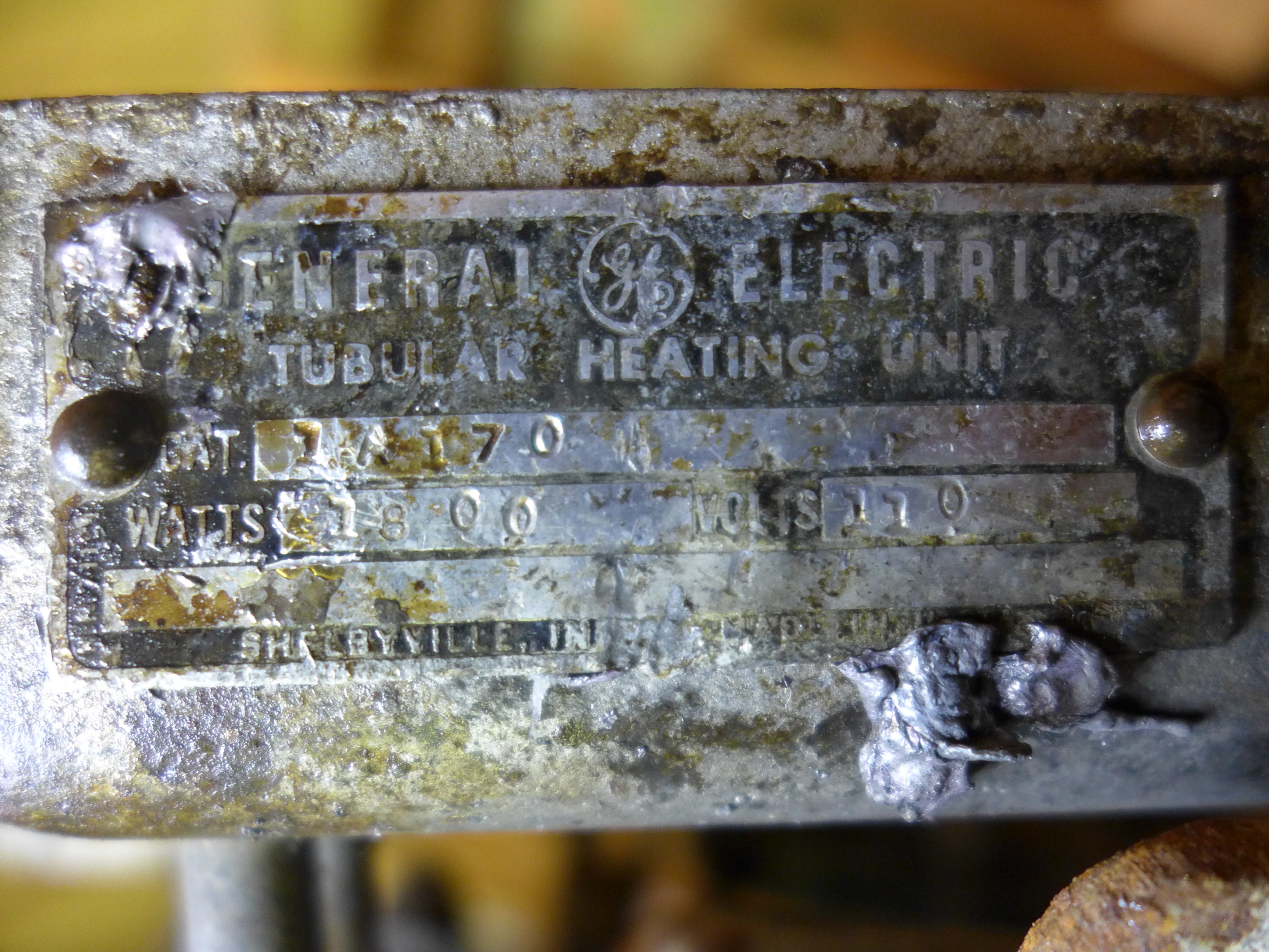
Also at some point the pot was converted from gas to electrical heat. I do not know the date of this conversion. 2 I do not know if it was done at the same time as the conversion of the drive to a Kimble motor. The two Pot Heaters are General Electric Tubular Heating Units, Model 1A170.
The brand and model heating element from which the Nipple Heater was constructed has not yet been identified.
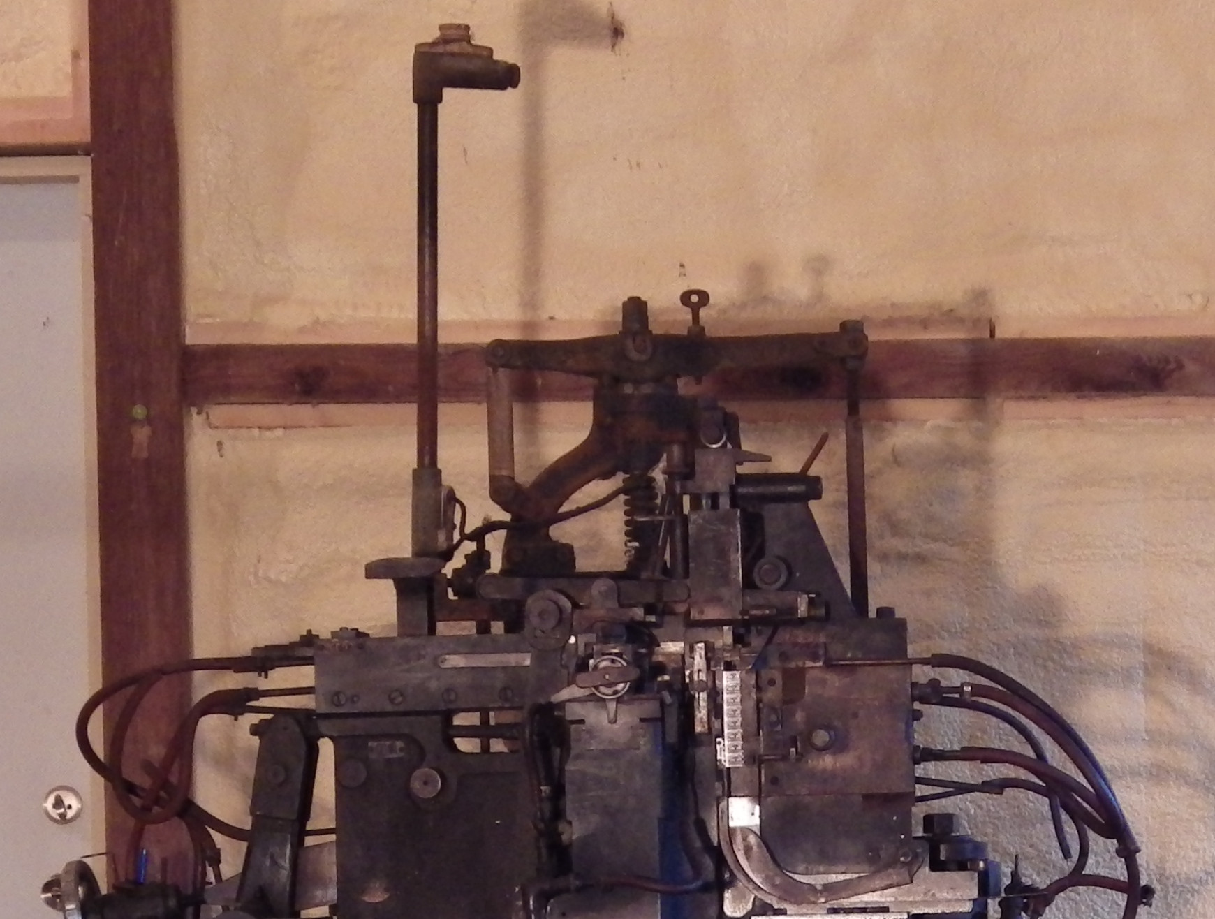
At the time this was done, a standard was raised above the machine and an electric light bulb placed in it. This was wired to light up when the Pot Heaters were energized (but was entirely independent of the state of the Nipple Heater). The socket used is a Crouse-Hinds No. 2706. This is a component the design of which dates at least to the late 1920s. The light bulb itself was not present as received, but must have been capable of operation in the 220V range (208V to 240V, more or less).
There are two heating elements. A nameplate survives on only one of them. I am assuming that this nameplate applies to the one heating element that it is on (that is, it is not a nameplate for the two of them as a system). I am further assuming that both heating elements are identical. (In any event, they have almost identical resistances, as measured.) As noted, these two heating elements are General Electric model 1A170 Tubular Heating Units. I have not yet discovered the manufacturer's specification for this unit. They are wired in series.
The nameplate says that the GE 1A170 is an 1800 Watt unit at 110 V. So for each heater individually we'd expect by calculation to see a resistance of 6.7 Ohms and a current draw of 16.4 A. As measured, the machine-left unit (port side; the one on the right side of the pot if you look from the back) has a measured resistance of 7.2 Ohms. The other (machine-right / starboard) has a measured resistance of 6.9 Ohms. These are close enough to the calculated values;
Since they are wired in series, this means that the two of them together will constitute a 900 Watt heating system (at 110V). The calculated resistance doubles to 13.4 Ohms and the current drawn halves to 8.2 A. (Using the measured resistance of 7.2 + 6.9 = 14.1 Ohms, this gives 7.8A and 858 Watts.)
However, in use these heaters were not connected to 110V, but to two of the legs of the machine's three-phase power at (presumably) 208V. Resistance doesn't change with the voltage, so it should still be 6.7 Ohms per unit by the nameplate values (13.4 Ohms total) or 7.2 + 6.9 = 14.1 Ohms as measured. The calculated current draw over 13.4 Ohms at 208V would be 15.5A and the resulting power 3228 Watts. The current draw over 14.1 Ohms at 208V would be 14.7A and the resulting power 3068 Watts. These are reasonable values.
It will turn out that the actual voltage supplied will be either 240V or 260V (as determined by the details of the phase converter I'll be using).
240V over the measured 14.1 Ohms gives 17A and 4085 Watts.
260V over the measured 14.1 Ohms gives 18.4A and about 4800 Watts.
I also have another phase conveter where I've seen the generated leg at up to 280V. 280V over 14.1 Ohms gives 19.9A and 5560 Watts. I have no intention of using this phase converter on this Barth, but given that such beasts exist in the field, it would be best to size the Pot Heater wiring to handle at least 20A (plus the Nipple Heater requirements, as discussed next).
The Nipple Heater is unidentified, but it measures 75 Ohms. At the presumed original 208V, it would draw 2.8A for a power of about 580 Watts. At a supplied 240V, it would draw 3.2A for 768 Watts. (At 260V this would be 3.5A and 900W; at the extreme 280V it would be 3.7A and a bit over 1 kW.) So it would be best to add 4A to the current capacity of the pot wiring to accomodate the worst-case scenario for the Nipple Heaters.
So the Pot Heater wiring before it splits into main and nipple heaters should be capable of 24A. Ignoring effects of temperature, this implies 10 AWG wire (which can handle 30A). The next smaller common gauge, 12, is only capable of 20A. That would just handle a best-case situation, but assuming the best case is never a good idea. (The values here are for regular MTW (Machine Tool Wire). It appears that the type MG high-temperature wire to be used for the final runs has a higher ampacity and could be thinner. I'll ignore this and use thicker wire. In power wiring, the bigger the wire the better.)
It is also interesting that the Nipple Heater power wiring configuration as received was quite unusual. Functionally, it was wired to the motor control circuit so that the motor switch also turned the Nipple Heater on. Physically, these wires were connected in a puzzling location. On a motor control switch (not just back then, but still today), there may be thermal overload elements which contain a little micro switch embedded in a fusible alloy. These are over-current devices; if too much current flows, the fusible alloy heats up and the switch causes the circuit to be interrupted. Because these involve heating a fusible alloy, they are (very confusingly!) called "heaters." They have nothing at all to do with the Pot Heaters. On this Barth, the Motor Starter Switch (a G.E. CR1062-B7 Manual Motor Starter) has two "heaters" (G.E. 81D-128). Electrically, these are on the far side of the switch and power flows through them when the switch is on. Physically, they happen to have an extra screw on them. ATF wired the Nipple Heater power circuit into the screws on these motor control thermal overload / overcurrent "heaters." This works, but it is just plain weird; it was very hard for me to understand it when I first encountered it.
Wiring the Nipple Heater in this way has implications. First, it means that there is no way to control its temperature. If the motor is on, the Nipple Heater is on.
Second, I suppose you could argue that there might be some small measure of safety in disengaging the Nipple Heater when the motor is turned off (because the metal in the Nipple will freeze and be less likely to drip when you swing the pot back). I'm not sure that I'm convinced by this, though.
I have not yet examined/tested the combination of the G.E. CR1062-B7 Manual Starter Switch and the G.E. 81D "Heaters" to see (a) what happens to the Nipple Heater circuit if the heaters trip the motor circuit and (b) whether an overcurrent condition on the the Nipple Heater circuit could cause the heaters to trip.
The machine was powered from an incoming 3-phase circuit which comprised precisely three legs, L1, L2, and L3. This was presumably what a factory/industrial electrician would call a "low voltage" 3-phase circuit. Today such a circuit runs at a nominal 208V AC between any pair of legs. This is 3-phase "delta" power, because you can draw a contact point for each leg as a dot and connect the three in a triangle in your electrical diagram. There was no fourth "neutral" line to the machine (which in 3-phase "Wye" configurations gives a convenient 120V between the neutral and any leg). THE MACHINE HAD NO GROUND WIRE.
However, we do not know anything about the actual circuit used in Elizabeth, NJ at the ATF plant. At the earlier Central Plant, ATF generated its own power. I have no idea what was present in Elizabeth.
The existing ex-ATF wiring is unsafe and cannot be used. The existing control components may or may not be usable, but represent a style of control engineering which would no longer be considered suitable. The compromise that I'm reaching between (a) getting the machine running and (b) its conservation is this: all of the existing electrical control system and power wiring may be removed cleanly from the machine. This process has been documented, and everything which is removed will be preserved with the machine. It is still possible, should it ever be desired, to return this machine to a state very nearly identical to that which it was in at the 1993 ATF auction.
Three electrical components will be retained, unaltered, on the machine. These will be powered and controlled by an entirely new electrical system which is pretty easy to distinguish from the older one. The components which will be retained are these: the motor, the two Pot Heaters (wired in series as one electrical component), and the nipple heater. Here are their electrical specifications and requirements:
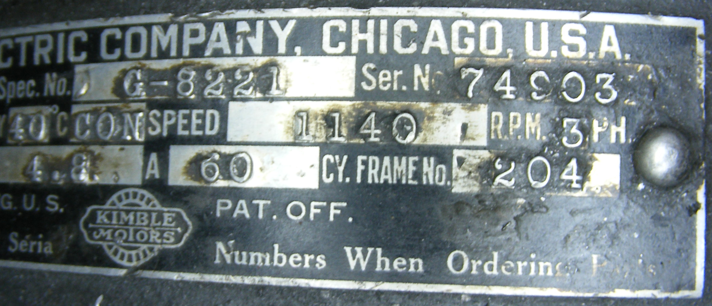
This is a standard industrial motor. Manufactured by the Kimble Electric Company, Chicago; date unknown. "Spec. No." [that is, model or catalog number] G-8221. 3-Phase, 220V 4.2A. Nominally 1.5 HP. 1140 RPM. This insulation class is "GA"; I don't believe that this class is in use any more, but the motor is rated for continuous duty at 40 degrees C. Kimble was known for its variable-speed motors, but this is a single-speed motor.
Although rated for 220V, is is reasonable to expect that this motor will run satisfactorily at a nominal 240V. (The only way to tell is to try it and check to make sure it does not overheat.) However, this motor is not "inverter rated." This means that its insulation is not designed for the extra heating induced by the non-sinusoidal power generated by an inverer or a variable speed drive (VFD). Some non-inverter-rated motors can handle this; some cannot. The only way to tell is to try it and see if you destroy the motor. (By the time you know, it is too late.) This will affect decisions about the new power supply.
It's difficult to get a single straight view of the motor ID plate without lighting glare. Here it is in two views, left and right.
These are General Electric "Tubular Heating Units" (sometimes sold under the trademark "Calrod," although these units are not so branded), Model 1A170.
As discussed earlier, these two heaters have measured resistances of 6.9 and 7.2 Ohms. They are wired in series, so the total is 14.1 Ohms.
The supply voltage will be 240V. So the calculated current draw for the Pot Heaters (not including the Nipple Heater) will be 17A for a power of just over 4000 Watts.
Due to the possibility of unexpectedly high voltages from three-phase power converters, the wiring should be sized for a worst-case (well, at least a very-bad-case) scenario of 280V. In this situation the Pot Heaters would draw 20A.
As discussed earlier, the Nipple Heater is unidentified. It has a measured resistance of 75 Ohms.
The supply voltage will be 240V. So the calculated currend draw for the Nipple Heater is 3.2A for a power of 768 Watts.
In a bad-case scenario with a supply voltage of 280V, the Nipple Heater would draw 3.7A.
To handle the bad-case 280V situation, the Pot wiring coming in must be able to handle 20A + 4A = 24A. This implies 10 AWG.
It would be possible to reduce the final wiring to the Pot Heaters to 20A capacity (using 12 AWG) and the final wiring to the Nipple Heater to 4A capacity (which could be 18 AWG). It is probably simplest just to use 10 AWG throughout, though.
The Pot wiring can be ordinary MTW (Machine Tool Wire) in flexible conduit up to a certain point. Beyond that, it must be type MG high-temperature wire.
The ampacity of type MG wire is higher than MTW, and so in principle smaller gauges could be used. Again, I'll probably play it safe and just go with 10 AWG even for the type MG wire portions.
The basic issue to be addressed revolves around two things: First, proper utility-supplied three-phase power typically is unavailable in the small or home shop environment. Second, the style of electrical loads in a type casting machine is unbalanced. The motor is actually a relatively small part of the load, but is often three-phase. The pot heating is the largest load, but it is always single-phase.
These issues are present with other kinds of metal type machinery as well - particularly Linotypes and Intertypes. Even though the present Journal entry is for the Barth, I'll refer at times to Linotype and Intertype power issues because in my own shop the same three-phase solution adopted for the Barth must also serve to power several Linotypes, Intertypes, Monotypes (and possibly a Ludlow, a Miehle Vertical press, and other equipment).
To begin with, we need to understand at a very simplistic level what true utility-supplied three-phase power looks like and how this differs from "shop-made" power solutions. It's not that hard. Really, it isn't. Yet when I begin discussing this with fellow enthusiasts who have either an interest in this or a need to know about it, at the point when I mention "three-phase delta" vs. "three-phase wye" their eyes glaze over and they cease to try to understand. This happens every single time, without exception. It's not that hard. Really, it isn't.
Three phase current as supplied by an electrical utility company has five wires.
One of these is the protective, safety, ground wire. This ground isn't part of the power supply (if it is disconnected, things will still run). It is there as a safety element so that if there is some fault in the device or wiring the current will short out to ground through the ground wire rather than through you (killing you). If you're lucky, nothing will ever happen on this ground wire. It should still always be present and correctly installed (there are entire books on proper grounding; it is not a simple matter!)
Three of the wires are the actual "hot" power-carrying wires. Typically, these will be called L1, L2, and L3 (or T1, T2, and T3 when coming out of a phase converter). Each of these wires is carrying Alternating Current (AC) in a true sinusoidal waveform. But the voltage of this power is measured between any two of the legs, not from the legs to ground. In the "low voltage" systems used in this Barth, this voltage would be a nominal 208V. (It's not 240V because you're measuring between waveforms which are 120 degrees out of phase with each other, not 180 degrees).
The last wire is neutral relative to all three of the hot legs. It is not the same as the ground wire. (Don't use neutral for ground, or ground for neutral!) The voltage between the neutral and any one leg is nominally 120V. This can be very convenient if your machine requires 120V for things like lighting or other peripherals (a Linotype does).
This five-wire utility-supplied three-phase is called a "Wye" system because if you're drawing a diagram of it you can put the neutral in the center and connect each of the three legs to it in a 'Y'-shaped figure.
Three-phase can seem a little weird if you're familiar with North American 120V single-phase. In 120V single-phase, you think of the hot wire as carrying the current in and the neutral wire as carrying it out. That's why you put the switch on the hot side of the circuit. In three-phase, each of the three hot wires (L1, L2, L3) function both as the source and return. So three-phase is more like 240V single-phase. This is why you have to put a disconnect switch on both hot legs of 240V single-phase and on all three hot legs of three-phase.
There is another configuration of three-phase power. If you omit the neutral, you have a four-wire system (three hot plus ground) which provides 208V (for a low-voltage system) between any two of the hot legs. If you draw a diagram of this, you end up with points representing each of the three legs and connections between them. This diagram is a triangle, so this configuration is called "delta" three-phase.
This is something that VFD (Variable Frequency Drive) enthusiasts tend to ignore. With modern motors, you probably can ignore it. With 100 year old motors, you can't.
A VFD may be a clean, elegant little electronic box and it may be the most modern solution to motor control. But conceptually it is exceedingly crude. True AC power gently pushes a motor around. A VFD bashes it around by hammering it with DC pulses.
A VFD does not in fact produce AC power. It produces pulses of DC power, each pulse at the same voltage. A single cycle of AC voltage varies smoothly from zero to max positive back through zero to max negative and back up to zero. To accomplish the same cycle, a VFD would emit a series of pulses, all at the same voltage (positive or negative). The pulses would start out short and then increase in duration through the first quarter cycle (where true AC power would be continuously increasing in voltage) up to the point in the cycle where true AC would be at max voltage. Then the pulses (still always at the same voltage) would decrease in duration during the second quarter-cycle (where true AC power would be continuously decreasing in voltage). The voltages would then go negative and this half-cycle would repeat at negative voltages. Because this output power consists of pulses of DC power at variable lengths (variable widths as you chart them), this technique is called Pulse Width Modulation (PWM).
A motor responds to this PWM as if it was AC, but it really isn't a true AC sine wave. The potential problem here is that the insulation on the windings in the motor is subjected to more stress when pounded by the pulses from a VFD than when receiving true sinusoidal AC power.
Many modern motors are designed to handle this, so for a modern installation this problem is not important. (Since the device to convert DC to (simulated) AC is called an "inverter," and since inverters have the same issue, these motors are usually called "inverter-rated" motors.)
But older motors weren't designed for this kind of abuse, and their insulation can break down. Some older motors probably will work fine on a VFD, others won't.
Unfortunately, the only way to find out is to try it. If the motor survives, it's fine. If the motor is destroyed, it wasn't.
If it is important to preserve the motor (as it is for this Barth) and also to use it, then VFDs are ruled out from the start.
The basic problem that the small shop faces in re-powering all electrically powered "hot metal" type casting machines (type casters such as the Barth, linecasters such as Linotypes, Intertypes, and Ludlows, and composing typecasters (Monotypes are the only major examples) is that the two major loads of the machine can differ in phase and always differ substantially in size.
The motor, which is often three-phase, is really not that big. A Linotype motor is about 1/3 HP. Even this monster of a Barth has a motor which is only 1.5 HP (about 1120W, which isn't that big by industrial standards). In more specific terms, the Kimble motor on this Barth is rated at 4.8A at 220V. Even if supplied at 208V (as it probably was) it would only be a 5.4A motor.
The Pot Heaters, on the other hand, are single-phase on all hot metal machinery of which I am aware. Linotype and Intertype pots are somewhere in the 14A range.
This Barth's heating requirements are greater than that (probably about 18.3A at the presumed original 208V, and a likely 20.2A at the 240V I'll be using.) In rough terms, this is 3.4 times the motor amperage at 208V or 4.4 times the motor amperage at 240V.
Driving a relatively large single-phase load from two legs of utility-supplied three-phase (with much smaller loads across the other two pairs of legs) is just fine. The power station isn't going to notice the imbalance. But driving such a load from a phase converter of nearly the same capacity isn't necessarily the best thing in the world. It will load the idler motor unevenly. It also means that you must size your phase converter's three-phase output to handle a load which is actually single-phase. This drives up the cost.
One solution to the problem of a highly unbalanced three-phase load is to split the machine's power supply into two separate supplies: three-phase to the motor and single-phase to the pot. This is quite reasonable (and is in fact what I am doing; I've also done it with a Linotype), but it does introduce a problem which I haven't solved yet.
Every machine must have a means of disconnect to remove it from the power supply (NFPA 79 -2018, 5.3.1.1: "A supply circuit disconnecting means shall be provided for ... each supply circuit connecting to a machine"). Now, on the one hand: (a) Multiple supply circuits are permitted, though discouraged (5.1.1). (b) A disconnecting means can be a "group of devices" (3.3.32). (c) A disconnecting means can be a plug (5.3.2(6)). So providing either two disconnect switches or two plugs is technically within code.
But I prefer to have actual disconnect switches in addition to plugs. Furthermore, I'd really like to have just one such disconnect switch.
But splitting a load into a three-phase circuit (three hot wires) and a 240V single-phase circuit (two hot wires) means that there are five hot wires to disconnect. Five or six pole disconnect switches suitable for the voltages in use here are quite breathtakingly expensive.
So I'll have two separate disconnect switches (plus two separate plugs). This is ok and in code, but I don't like it. Since ultimately I'm going to be powering everything from the same 30A 240V single-phase circuit, I may just wire up a separate distribution sub-panel which plugs in to the 30A power source, with receptacles for the two single-phase supplies to the Barth Pot and the phase converter. At the input to this panel I'd put a single 1-phase (2-pole, as it's 240V) disconnect switch which would disconnect all power at a single point.
There are many possible solutions the the issues of drive power and pot heat, considered both separately and together. I'm sure I've missed some in this survey. I considered them all (well, except static phase converters, which have little merit).
1. Convert Back to Lineshaft Drive
This isn't as far-fetched an idea as it might seem.
It would return the machine to its original state of design (though as we do not know when this particular machine was built, we do not know if it was ever actually driven by lineshaft or if it was driven electrically from the start). It could be done without touching the existing motor or any of its electrical controls; as such it presents an excellent option from the point of view of conservation. It would also look amazingly cool :-)
Such a belt drive could either be constructed from components contemporary to this machine (that is, from vintage lineshaft components) or from modern components in a modern style. The first of these options would be costlier, and would require sourcing these components through the community of vintage machinery collectors. The second would be relatively simple, but would present a potentially awkward appearance (say, a modern motor with a V-belt reduction drive to a final flat pulley belted to the Barth). However, if appearance was an issue the underfloor drive design used in the ATF Chicago foundry could be adopted (the drive system beyond the belt was invisible in this style of installation).
This approach would reduce the remaining problem to one of the pot electrics, and would suggest (for consistency) the reconversion of the pot back to gas heat (see below).
Despite its appeal, I did not choose this option.
2. Convert the Pot Back to Gas
This is exactly what was done on all of the surviving Barths which were returned to service prior to this one (but these conversions did keep the electric nipple heater.)
It has the advantage that it reduces the electrical issue to the motor, and that's easier to solve on its own.
Gas vs. Electric pot heating is also a matter over which their are Strong Opinions. I have one good friend who rips out all electric pots on his machines and replaces them with gas because it is obviously so much simpler and better. Another friend has delayed running an electrically heated machine because of the dangerous and mysterious nature of electrical systems (and they can be dangerous - and certainly the older systems can be mysterious). But I have another good friend who replaces every gas pot in his machines with an electric version because he nearly blew up his basement with a gas leak. And other friends have delayed running gas machines because of the difficulties of exhaust ventilation.
But no original Barth gas burners survive.
Caution should also be exercised when using gas burners of this vintage on fuels other than the original manufactured gas (coal gas, often called "town gas") for which they were designed. The first real scientific study of gas burners was done by the US National Bureau of Standards around 1920. Burners before that, such as the one designed for the Thompson Type Caster and supplied until the end of its production, typically had an insufficient mixing chamber (none at all in the case of the Thompson; the bell is not a mixing chamber). After considerable experimentation, I found that I was unable to run an original Thompson burner off of LPG (Liquified Petroleum Gas, which in the USA consists mostly of propane), which is a gas several times heavier than the town gas used originally in it. At any pressure, the incomplete combustion inherent in the Thompson burner cause my carbon monoxide alarm to trip.
I run both gas and electric pot heating, carefully, and with modern gas burners.
The only three-phase load is the motor; the pot is single-phase. Replace the motor with a single-phase motor and you've solved the three-phase problem. In the case of the 60 point Barth, the resulting machine would be powered by a 240V single-phase circuit (assuming a 240V single-phase motor) and have no need of 120V. In the case of a Linotype, the resulting machine would be powered (at least here in North America) by a regular 120V/240V four-wire circuit as commonly used on household appliances.
The advantage here is simplicity. It also makes things easier for future custodians of this machine.
There are two disadvantages. First, from a conservation point of view, this alters the machine by removing the original motor. This motor is (a) heavy, but (b) potentially useful elsewhere. The chances of it going missing over the years are high. This particular Kimble motor does have a strong historical association with this particular Barth type caster. Second, from a practical point of view this is a pretty big motor for single-phase. Such motors exist, but they aren't cheap when new. They can be cheap secondhand, but the Barth takes an 1140 RPM motor; this speed is less common. Cheap secondhand single-phase 1140 RPM 1.5 HP motors can be hard to find.
There is a third consideration: In my shop I was going to need three-phase for other machines anyway. Might as well provide for it now.
So I opted against this for the Barth.
But if this were a Lanston Monotype-Thompson, I'd almost certainly remotor to single-phase (the motor of the Thompson was never as integral to the machine from a conservation point of view, and the Thompson takes any of a vast number of quite common fractional-HP motors).
4. Get an Engine-Driven Three-Phase Generator
In effect, this option turns you into a mini-utility company.
The advantage is that the generator in such a setup would provide true sinusoidal three-phase power. (I haven't investigated them enough to know if they can provide three-phase Wye or just Delta.) I suppose if one were to size the unit so that it was large enough this would overcome the unbalanced load issue and you could simply run both motor and pot from the same supply.
This approach has two disadvantages which would not be problems for me: noise and exhaust fumes. I live far out in the countryside, and my neighbors (all farmers) run bigger diesels than this every day.
It has one disadvantage which caused me never to seriously consider it: maintenance. This Barth will not be run daily, and it won't be run at all over the winter. I know from experience that if I leave something like a rotary phase converter (see below) sitting idle for a few years (in dry indoor conditions) I can just plug it in and go. I know from experience that if I try the same with a gas or diesel engine (especially outdoors, and optionally with mice) I'm looking at a maintenance project every time I want to use it.
5. Drive a Three-Phase Generator from a Single-Phase Motor
This is conceptually very simple. Acquire a big cheap secondhand single-phase motor. Acquire a three-phase generator. Mount them both to a base and connect them with a V-belt. Run the single-phase motor under regular shop power and get three-phase at the output of the generator. But in practice you don't find this solution very often (I've never seen it).
The advantage of this setup is that, like the Engine-Driven Generator (see above), you have pure sinusoidal three-phase power evenly balanced between legs. Both it and an Engine-Driven Generator will produce better quality AC power than either a Rotary Phase Converter (RPC) or a Variable Frequency Drive (VFD). When compared to an Engine-Driven Generator, this solution is easier to run indoors and avoids the maintenance issues of a gas or diesel engine.
The first objection is that it is twice the cost, size, and weight of a Rotary Phase Converter (see below).
The second objection is that it probably produces better power than you need. The power from an RPC won't be evenly balanced between the legs, but that probably doesn't matter. The power from a VFD isn't actually AC power, but if your motor is "inveter-rated," that's ok.
The major problem is that finding the three-phase generator can be difficult. It can't just be a big cheap three-phase motor run in reverse. Yes, in principle a generator is just a motor backwards. But there are details. The problem is that most big three-phase motors are induction motors which generate their own magnetic fields, not permanent-magnet motors. So you can't just spin an induction motor and get a generator. There are ways to get around this, but they require a greater level of electrical knowledge than I possess.
So I opted against this. It would be fun to try it someday, though (and that makes a good excuse to collect more big old motors).
6. Get a Rotary Phase Converter (RPC)
Rotary Phase Converters (RPCs) seem a bit magical at first, but conceptually they're pretty simple. (Getting them right, however, is why you get your degree in Electrical Engineering.)
If you take the two hot wires of a 240V single phase input (call them L1 and L2) and shift one of them by 60 degrees using capacitors, you can drive two of the three sets of windings in a three-phase motor. The bit of "magic" is that this self-same three-phase motor is now also a generator. So it will generate a third leg for you. If you then connect up to the output of this device, you get the first input leg (L1) passed through as an output (call it now T1). The second, shifted input leg (L2) is also passed through (call it now T2). The third leg, generated by the motor-as-generator, is T3. It's pretty cool.
The advantage of an RPC is that it gives you true sinusoidal three-phase power. It's a nice, heavy, robust analog solution (the "idler" motor, at least; sometimes the controls can be digital). When compared to Variable Speed Drives (VFDs, see below; these are now the primary competitors to RPCs) it has the advantage that it scales better to larger sizes (at larger loads, solutions such as Variable Speed Drives (VFDs, see below) can become prohibitively expensive) and it does not suffer from RFI (Radio Frequency Interference) problems.
The disadvantages of an RPC are cost (but VFDs in the sizes were' talking about aren't all that cheap either) and noise. RPCs vary in their noise levels, but none run silently.
(An RPC may also presents a danger for the unwary. Because L1 and L2 are passed through as T1 and T2, unless the switch to the RPC and its idler motor disconnects L1 and L2 completely they remain hot at the output of the RPC (and anything connected to it, such as the motor on the machine you're driving) even when it is turned off. This is a lethal level of power at a location where future user who might be unfamiliar with RPCs might not expect it. (You don't often encounter devices which output full line power even when they're turned off.)
Three-phase current from an RPC does differ from that from a utility company in two ways: voltage and delta vs. wye.
An RPC generates delta three-phase. If you need wye, you need to feed the output of the RPC into a delta-wye transformer. These aren't cheap.
Because the single-phase input voltages are higher than those of comparable utility-generated three-phase, the output voltages of an RPC are higher as well (the input voltages are passed straight through; I don't understand the engineering well enough to know why the generated leg is typically even higher). For example, in my new American Rotary ADX-5 RPC (with which I'm quite pleased), T1 to T2 is 240V (just like the single-phase input) and both T1 to T3 and T2 to T3 are each solidly 261V no-load. In my 20 year old commercially purchased converter (with which I'm less happy), T1 to T2 is 240V (as expected), but T1 to T3 measures around 256V and T2 to T3 can be 275V or higher (I've measured 280V at times, depending on the quality of the input power).
The options with RPCs are to build one yourself (big old three-phase motors are cheap) or to buy one (they're not so cheap). Some experiences:
More times than I can count, I've had it explained to me in serious tones that I should never waste my money on a commercial phase converter because I could just get an old motor for free, add some capacitors, and start it by wrapping a rope around the motor shaft and pulling. Great emphasis is always placed on the rope. Figuring out the capacitors is always glossed over. Nobody seemed actually to have built such a converter, but it was the One True Way. In each case this advice represented a sincere effort to fulfill the moral imperative of saving a dollar, regardless of the cost.
Yes, it can be done. A friend of mine (not one of the ones just mentioned) has built one. I've also got a shop-built RPC by an unknown maker that came along with an old milling machine. But figuring out the capacitors isn't intuitive to someone without a background in electrical engineering. And relying on a rope just means that you're not bothering to figure out how to start your idler motor electrically.
As an example, the shop-built RPC that I have is based on a 7.5 HP General Electric motor. I haven't traced the wiring through to figure out which output legs are pass-through (T1, T2) and generated (T3). But in a test run the Black-to-Red voltage was 237, Black-to-White was 240, and Red-to-White was 218. This is pretty good, actually.
This RPC also provides a good example of why you can't go from hot to ground in 3-phase Delta. Black-to-Ground and Red-to-Ground are about 118V. but White-to-ground is 198V. The three-phase output does not have a common neutral.
Curously, although this RPC was clearly made for the fabled rope-start (complete with tape wrapped around the motor shaft for more friction on the rope), it self-starts when you plug it in. It doesn't have an on/off switch or a disconnect (yet!); the previous owner had hard-wired it into a panel and was using the circuit breaker as a switch (do not ever do this; a circuit breaker is not an on/off switch).
As far as commercially made RPCs go, I've had two experiences.
In the late 1990s, I purchased a [brand suppressed on an "if you can't say anything nice" basis]-brand 7.5 HP RPC to power my lathe. I'm still using it my Machine Shop. It has had two problems. First, it was supplied without a starter for the motor. An adequately trained industrial electrician could of course just pick one and go. But for an amateur without any background in this field, selecting a proper starter is a nontrivial undertaking. Second, its output voltages aren't very stable and the generated leg is way too high (as noted earlier, T1 - T3 and T2 - T3, which should be the same and close to 240V, are 256V and 275V no-load). This tends to trip the overvoltage protection on my lathe (which is really annoying in the middle of a cut). It is also very noisy.
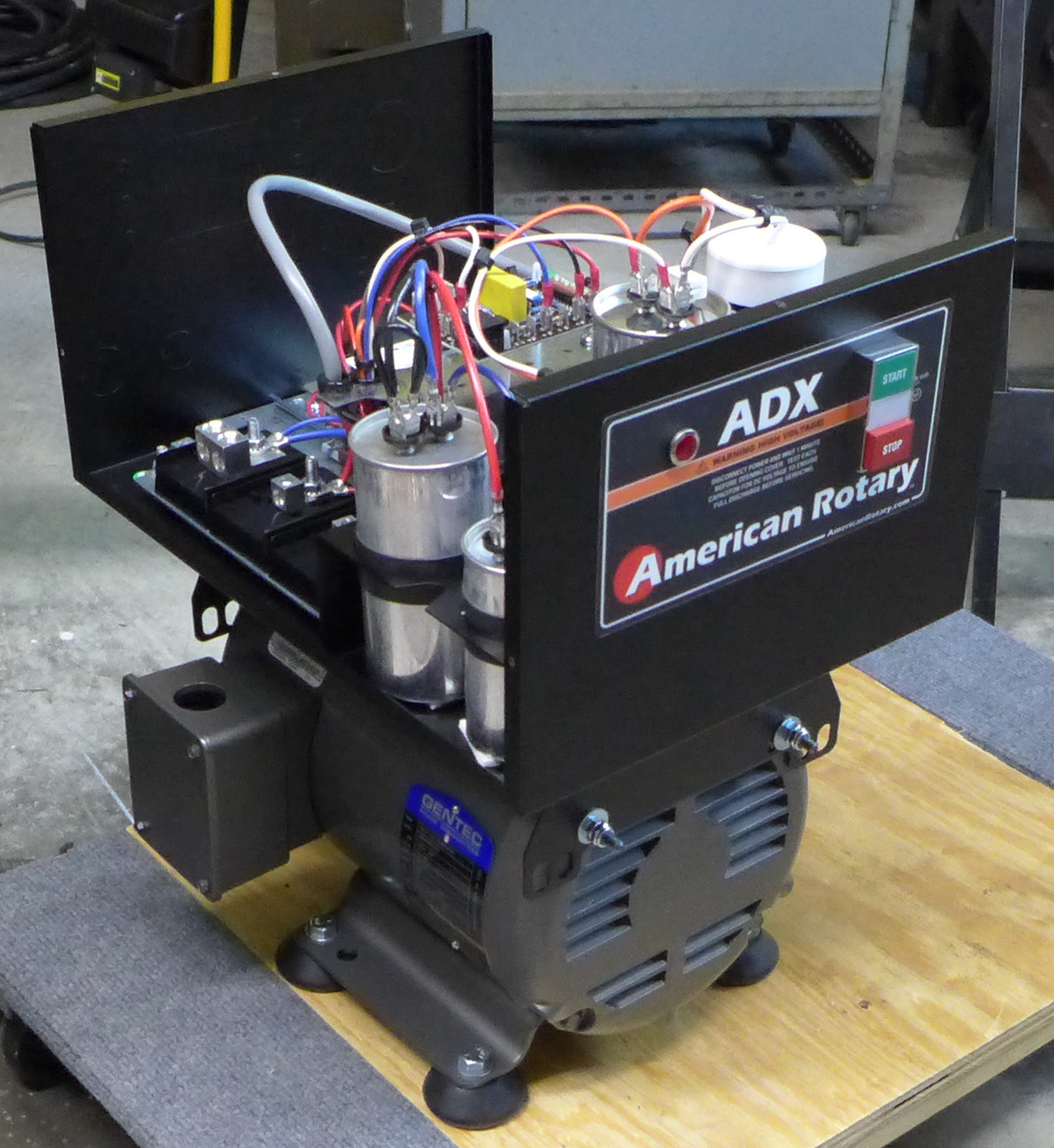
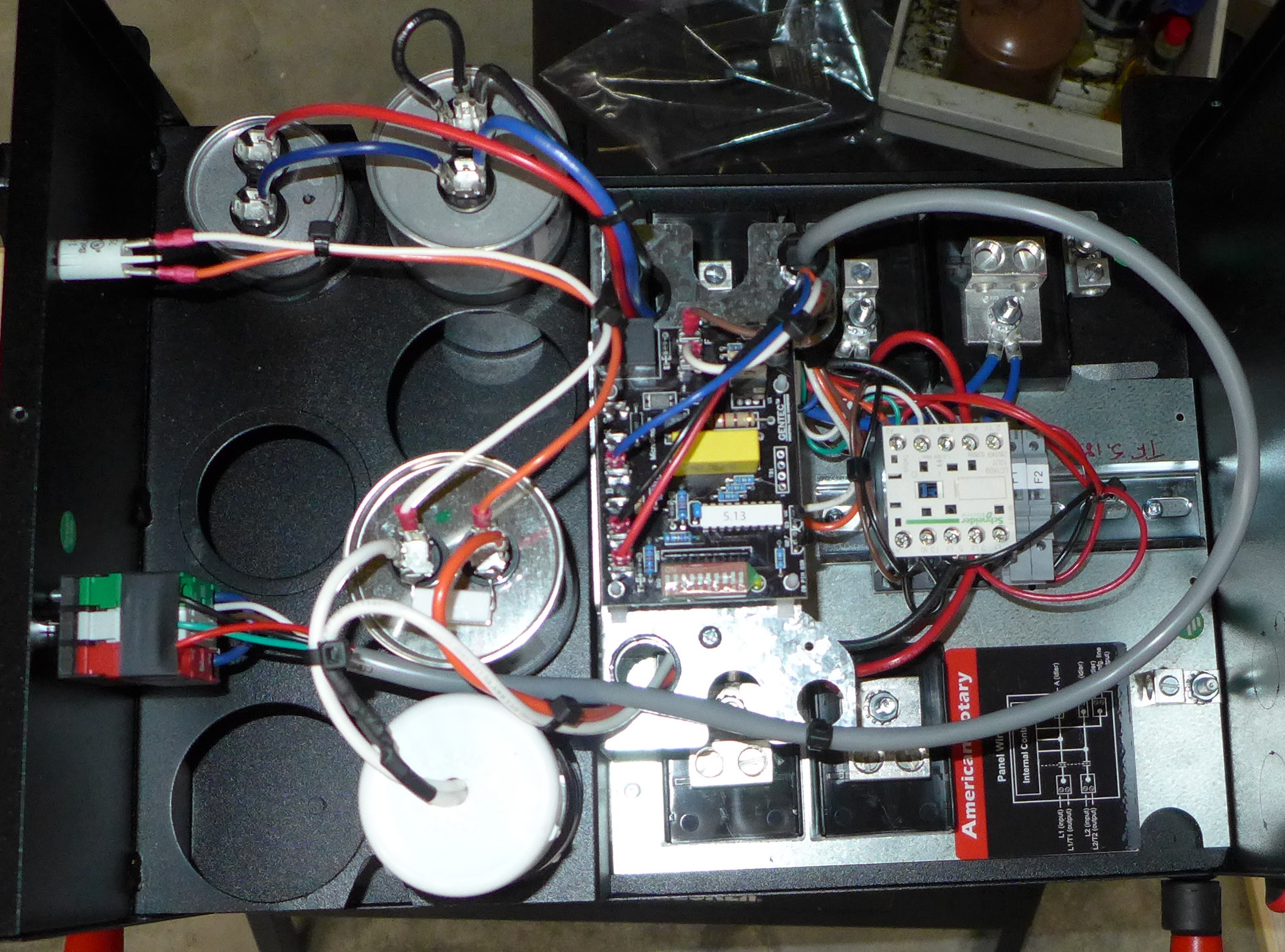
For the Barth, and to power the Linotypes, Intertypes, Monotypes, and a Miehle vertical press in my Printing Shop, I purchased an American Rotary (i.e., Gentec) ADX-5 digitally controlled converter. It came with all of the starter electronics installed and produces very stable output much closer to the input voltage (240V no-load on T1 - T2 and 261V on both T1 - T3 and T2 - T3). So far, I like it much better. It runs much more quietly, produces better output voltages, and was much easier to install.
So in summary RPCs are a quite reasonable option, and are still preferable to VFDs in certain situations (particularly when dealing with antique non-inverter-rated motors). If you're comfortable building one, go for it. If not, look for one which has modern controls and has its idler motor starter included.
7. Get a Static Phase Converter
I never seriously considered this option. A Static Phase Converter isn't a phase converter at all. It's a device which allows you to run a three-phase motor using the two hot wires of 240V single-phase North American domestic power. Because it really isn't driving the motor completely, the motor can never develop full power.
I don't really know if this Barth needs 1.5 HP, but that's the motor ATF put in it, so I will assume it does. Going with a VFD would mean that I'd have to replace the existing motor with a 2.25 HP three-phase motor. This is an issue both from the point of view of conservation (swapping out the motor) and of practicality.
8. Get a Variable Frequency Drive (VFD)
A VFD is an electronic device which takes input AC power (often single-phase) which is at whatever fixed frequency the utility company supplies. Internally, the VFD converts this power to DC. It then outputs power (often three-phase) at whatever frequency you select (within the limits of the VFD, of course). But this output power isn't actually AC power at all; it is a series of variable-length DC pulses which a load such as a motor reacts to as if it was receiving sinusoidal AC power. (See the section Background: Sine Waves vs. PWM/"Inverter" Power, above for a discussion of this.)
If you take a VFD which is designed for single-phase input and three-phase output and just set it permanently to 60 Hz (here in North America) you have a phase converter.
VFDs are small, versatile, and increasingly popular. They're not cheap, but they're cost-effective when compared to RPCs.
They do have some issues. They can be a bit complicated to wire. But this is just a matter of reading the manual and being careful. They do not scale economically above a certain size. In my research, I found that at the present moment in time (2018) a VFD was reasonable in terms of cost for the smaller motors in my printing shop, but not for the 5 HP motor of my lathe. In the future this will certainly change. They generate serious RFI (Radio Frequency Interference), which may or may not be a problem. This can be suppressed, but that requires additional components.
The issue with VFDs which prevented me from considering them seriously for this or any other antique machine project was the problem (described earlier) that the output power from PWM devices such as VFDs can destroy older non-inverter-rated motors, and that the only way to find out is to try it and to see if the motor is destroyed or not.
After all of this, what will I do?
I'll remove almost all existing electrics from the machine, cleanly, and conserve them. It will be possible to return the machine to very nearly its 1993 ATF auction state. I'll keep the Pot Heaters, Nipple Heater, and Motor.
I'll split the power into two separate circuits: three-phase to the Motor and single-phase to the Pot.
I'll drive the Motor from an American Rotary ADX-5 digitally controlled Rotary Phase Converter. This unit will be installed so as also to provide three-phase power for other machines in my Printing Shop.
(Aside: This portion was completed on 2018-05-26.)
I'll control the Pot heating power via a new digital control unit (yet to be full designed, but based on a modern replacement Linotype pot controller designed by Mark Turpin).
1. I do not know the date that this final power drive conversion was done. It is likely that the motor now on the machine was the one used, but this is not certain. It is entirely possible that this motor was a secondhand motor fitted as a replacement at some later date.
The date of this Kimble G-8221 motor is not known. However, it looks much more modern than motors of the 1920s. It must date to at least the 1930s. By 1944, the Kimble Electric Co. had become the "Kimble Electric Division of Miehle Printing Press & Mfg. Co." (This is attested by an advertisement in Plastics Magazine (June 1944), p. 117 as reprinted on the VintageMachinery website at: http://vintagemachinery.org/mfgindex/imagedetail.aspx?id=14168 ). So the motor must date to the late 1930s or very early 1940s.
In the absence of further information, based on the approximate date of this motor we can guess that the final conversion of the drive system was done in the 1930s or very early 1940s.
2. I haven't yet tracked down the date of introduction of these GE 1A170 Tubular Heating Units, but catalog evidence can suggest a range. In the 1300+ page 1921 G.E. catalog, no heaters of this kind are listed in the industrial heating section (which does include other heaters for soft metals). In a 1941 G.E. catalog of Electric Heaters and Heating Devices, this style of heater is featured but only a few 1A models are listed. By the 1955 G.E. Electric Heaters and Heating Devices catalog, no 1A models were are listed at all.
All portions of this document not noted otherwise are Copyright © 2018, 2022 by David M. MacMillan.
Circuitous Root is a Registered Trademark of David M. MacMillan.
This work is licensed under the Creative Commons "Attribution - ShareAlike" license, version 4.0 International. See http://creativecommons.org/licenses/by-sa/4.0/ for its terms.
Presented originally by Circuitous Root®

