If you strip everything else away, the basic mechanism without which the top-slide won't work is a handle turning a feedscrew. In this design, the handle is rigidly keyed to the top-slide feedscrew. You could remove all of the "dial" mechanism and still run the lathe with just the handle and screw.
The Handwheel is just a solid piece of steel, p/n 73043-1. It has two Handles screwed into it (p/n 73035-1 (short) and 73034-1 (long). There is no need to remove the Handles when disassembling the Dial (unless you want to; I did, although I put them back on before taking the photo below).

The inside of the Handle is tapped for two Spigot Securing Screws, p/n 87495-0. These are hex socket head screws, shown in place below.

These screws secure the Spigot, p/n 87509-0, to the Handle. They become a single unit; what happens to the Handle happens to the Spigot, and vice versa. (In many of the later photos I'll just show the Spigot, but in each case think of its motions as those of the Handwheel.)
Although it isn't entirely clear from the photo below, the smallest diameter of the through-hole of the Spigot is slightly less than that of the through-hole of the Handle. This will allow the whole unit to be held on, as seen later.


The Spigot slides onto the Screw, p/n 73180-1. The Screw is a relatively complex turned piece, which has an integral coller on it as well as straight and threaded parts. The Screw also has a keyway in it, and a Woodruff Key, p/n 73061-1. (The Key is hard to distinguish in the photo below.) Note also that the Spigot has a Key, or a sort of a tooth, driven into it. It does not engage the Screw, and thus isn't relevant right now, but this Spigot key will become very important later in the discussion.


The Spigot is an easy sliding fit over the straight cylindrical portion of the Screw. However, at least on my machine, the Spigot is a light driving fit over the Woodruff Key. (It is not clear to me whether this Key is an original part or not. It is driven so tightly into its seat that I can't get it out without destroying it.) You'll note in the various photographs that I haven't actually driven the Spigot all the way back on. I will, of course, for final reassembly. But I didn't want to drive it on or off any more than I had to, so in these photos you'll just have to imagine that the Spigot slides all the way over the Key, right up to the shoulder of the next diameter of the Screw. In the photo below, I've slid it about halfway along the Key; any further and I'd have to get out a hammer.

The attentive reader may notice something odd when comparing the first two photographs of the screw-and-spigot above with the third. In the first two, it appears as if there is a radial groove cut in the Screw just to the left of the Key. In the third photograph, this is gone - the Screw is a straight cylinder all the way up to the next shoulder. What appears to be a groove was in fact a ring/ridge of hardened grease. When I went back the day after taking the first two photos to take the third, I noticed this ridge and chipped it off. Here's a close-up of the Screw at this point:

The Spigot is retained on the Screw by a hex socket head cap Screw, p/n 87492-0 (144-7027), and a thick machined Washer, p/n 87520-0 (931-0294). Here they're shown lightly threaded into the Screw, with the Spigot that they would retain off to the side.

Here, I've slipped the Spigot on the top-slide lead Screw and loosely fitted the retaining Screw and Washer:

This Handle + Spigot + Screw is by itself enough to operate the Top Slide (without any of the graduated dials), if only given way to hold it in place.
When installed on the machine, the Screw runs through a brass Nut, p/n 73030-0, which is in turn secured to the lower half of the Top Slide (the "Swivel Slide, p/n 73442-0). See the parts book for an illustration of this.
Since the Top Slide rotates, it can be difficult to refer to its linear motions unambiguously. Let's make an arbitrary definition to use here:
"In" means a motion of the Top Slide where it moves in the direction opposite its handle. If the Top Slide is oriented parallel to the Ways of the lathe (with the handle on the right), then "In" means leftward. If the Top Slide is oriented perpendicular to the Ways of the lathe, with the handle at the front of the lathe, then "In" means toward the back of the lathe, away from the operator. Generally, "In" corresponds to feeding the tool into the work. To turn the Top Slide "In," you turn its Handle clockwise.
"Out is the opposite of "In": the Top Slide moves in the direction toward its own handle. If the Top Slide is oriented parallel to the Ways of the lathe (with the handle on the right), then "Out" means rightward. If the Top Slide is oriented perpendicular to the Ways of the lathe, with the handle at the front of the lathe, then "Out" means toward the front of the lathe, toward from the operator. Generally, "Out" corresponds to backing the tool away from the work. To turn the Top Slide "Out," you turn its Handle counterclockwise.
When you turn the Top Slide "in" (clockwise on the Handle), the Screw rotates clockwise in this Nut and tries to pull the Handle toward the Nut. To cause this to happen, the Screw must be restrained from moving inward in the Dial Assembly.
When you turn the Top Slide "out" (counterclockwise on the Handle), the Screw rotates counterclockwise in this Nut and tries to push the Handle away from the Nut. To cause this to happen, the Screw must be restrained from moving outward in the Dial Assembly.
The second of these two needs is met in an almost crudely simple way with a part called the "Keep Assembly," p/n 73054-1. It is also what attaches the entire Dial unit to the machine.
Just for reference, here's the page from the parts list with the entire setup:

Here is the Keep Assembly, viewed from the side facing the Handwheel:

Here it is viewed from the side facing the Top Slide, with the two hex head (not socket) screws, p/n 87496-0, which secure it to the Top Slide, shown inserted.

The Keep Assembly is screwed firmly to the Top Slide; it does not rotate with the dials.
One of two ways to remove the Dial Assembly is to remove the entire Dial Assembly plus the feedscrew, together. I find this easiest, as it allows the whole unit to be taken to the bench for work. (The alternative involves pulling the Spigot off. Perhaps that is the normal way, but as the Spigot is on my machine a driving fit on the Key on the Screw, this is, for me, difficult.) Here's a view of the whole Dial Assembly on the lathe, with the two hex Screws which hold the Keep Assembly to the Top Slide loosened slightly:

With the Screws loosened, turning the Handle counterclockwise now screws the entire Dial Assembly away from the Top Slide. Here it is screwed out partway:

There isn't enough room in the sides of the Keep Assembly to remove the two Screws entirely. So the procedure is to unscrew them a bit, then screw the whole Dial Assembly out some, then unscrew the two screws a bit more, then screw the whole Dial out a bit more, and so forth.
With the two Keep Assembly Screws clear, nothing retains the Top Slide Screw in the Top Slide save the fact that it is screwed in. It can simply be unscrewed and removed.

(All of this suggests that it is most important to remember to put these two Keep Assembly Screws back in place before reassembling the entire Dial Assembly.)
The Top Slide Screw goes through the Keep Assembly. It's an easy sliding fit (as of course the Screw must rotate but the Keep Assembly does not). Here it is almost all of the way in:

Here it is as far as it can go, with the "collar" on the Screw snug up against the Keep Assembly:

It doesn't look like much, but in fact the interface where this "collar" bears upon the Keep Assembly is an important bearing surface. The Keep Assembly is fixed to the Top Slide. This collar pushes against the Keep Assembly. So when you are turning the Handwheel counterclockwise to move the Top Slide "out," this collar pushes against the Keep Assembly and, in turn, pushes the Top Slide out away from the Nut.
It is a plain steel-on-steel bearing surface with no special fittings. There's no bronze bushing; there's no ball bearing. It's just the flat steel surface of the "collar" rotating on and pushing against the flat steel surface of the Keep Assembly.
The Keep Assembly screws flush onto the Top Slide. There is a hole cut in the Top Slide to accomodate, with clearance, the "collar" on the Screw. You can't see it at all unless you pull the Dial. At least when they designed an inadequate bearing they had the decency to hide it. :-)
Here's the view from the other side. The wide ring on the Keep Assembly around the shaft is just staining of the metal. In the photo below, no washer has yet been installed here.

The inside bearing on the Keep Assembly, the one which comes into play when you move the Top Slide "in," is much nicer. Here are the two washers and the radial roller bearing which constitute it. These are what is identified in the parts list as "Thrust Washer" 87516-0. (It is possible that the radial bearing was a later enhancement - or maybe it is somehow implied, as the drawing shows what looks to be a "three layer washer.")

And here's where they go. This is a view of the inside of the Keep Assembly. The Spigot is on the far right; in use it would be pushed leftward, snug up against these bearings.

But there is something wrong here. This is the the order of these three parts as they came out of my lathe. (I was careful about it.) But this order makes no sense: two washers, and then an exposed side of a radial roller bearing? My lathe didn't come straight from the factory, though. It came out of a high school, and may well have been tinkered-with. I'm going to guess that the actual order is NOT as shown in the photo above, but instead has the bearing in-between the two washers. The patterns of grease buildup on the washers actually indicate that this was the way these parts were installed for most of their lives.
So this is the order I think they should be in:


In the image above, the Thrust Washers (and bearing) are just hanging on the shaft. When the entire Dial Assembly is put together, another part which is primarily part of the dial mechanism serves a secondary function of locating these radially. So for now just assume they'll be held in place. As before, also assume that the Spigot is pressed all the way to the left against this Washer assembly. (You can see the marks from it on the rightmost Washer.)
The Keep Assembly is drilled radially with an oil passage. Here it is on the outside. It is capped by a driven-in oil hole cover with a spring-loaded ball fitting. (For a very similar (but not identical) modern example of such a fitting, look up the Gits Manufacturing Company "Style GB Ball Oiler," Nos. 520, 521, or 522 online, or search McMaster-Carr for "Easy-Fill Oil-Hole Covers.")

Here's the oil hole on the inside. It's just a hole. The Screw as it passes through the Keep Assembly in theory doesn't touch it, so the oil delivered here doesn't lubricate the Screw. Rather, it flows to each side and lubricates (one hopes) the outside plain bearing and inside roller bearing.

It is most easily oiled using a pressure-fed oil gun such as this one:

I got this particular oil gun at Harbor Freight (an American discount tool importer) several years go. They no longer carry it; the currently (2012) imported version has a transparent plastic can. What the all-metal version really is, I believe, is a Wufu brand, model YQ-A High Pressure Fed Oil Gun by the Zhejiang Refine Wufu Air Tools Co. Ltd (formerly Zhejian Wenling Shinian Hardware Factory).
Any oil gun or can with a sufficiently fine tip should work, however.
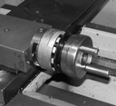
So here is the complete mechanism for driving the Top Slide, loosely assembled. If I were to tighten up this assembly and put it back on the lathe, I'd have a fully functional Top Slide, less only the graduated dials.
In simplified terms, the Handle/Spigot/Screw assembly turns to move the Top Slide along the Screw. This Assembly is held in place on the Top Slide by two bearings on a Keep Assembly: a plain bearing on the outside of the Keep Assembly and a radial roller bearing on the inside. The outside bearing is a collar integral with the Screw. The Keep Assembly and the inside bearings are held captive betwen this collar and the Spigot.

The parts shown above are also those called out as separate items in the parts book. What remains to be added to these parts is the Dual Dial Cartridge, p/n 87476-0. This Cartridge is presented as a "black box," with no internal detail. In the next section, The Dual Dial Cartridge , I'll open it up.
All portions of this document not noted otherwise are Copyright © 2012 by David M. MacMillan and Rollande Krandall.
Circuitous Root is a Registered Trademark of David M. MacMillan and Rollande Krandall.
This work is licensed under the Creative Commons "Attribution - ShareAlike" license. See http://creativecommons.org/licenses/by-sa/3.0/ for its terms.
Presented originally by Circuitous Root®
Select Resolution: 0 [other resolutions temporarily disabled due to lack of disk space]