Note 1: This is still very much a draft. I haven't even fully proofread it - much less had it peer-reviewed to correct errors. It will contain errors; I'm sure of that. If you use it for anything, please use it as a trigger for your own research. Don't cite it as an authoritative source, because it certainly is not.
Note 2: This discussion is clearly far too long for a single continous web page. I've left it as one page, though, because I'd like readers to be able to save local copies with a single "save" command on their browsers.
I was trained initially as a programmer, and therefore tend to think in programmers' terms. In particular, since ASCII (a 7-bit code) fits into 8-bit bytes, and since programmers often manipulate ASCII numerically, I tend to think of character codes as if they were simply binary numbers.
This is a mistake. A code is just a code - a mapping of meaning to representation. It happens (well, it happened by design) that in ASCII it is possible to consider the representation as bits and to do meaningful arithmetic on them ('a' + 5 = 'f', and 'A" + 5 = 'F') This is not, however, necessarily the case with other codes. EBCDIC, for example, traces its origins back through the punched card, and arithmetic in it can get tricky. More to the point here, ASCII is as much a 7-bit punched tape code and communications line control code as it is anything else. Several of the more important punched tape and pre-tape printing telegraphy codes which predated ASCII were not designed with binary arithmetic in mind at all.
(Indeed, although binary numbers have been known for centuries, it is suggestive that all three of the other codes I'll consider here were developed prior to the machine implementation of binary arithmetic by Claude Shannon (1937) and his introduction of the term "bit" (1948). For tape-based codes such as the Teletype code, the term "level" is more appropriate than "bit," and for pre-tape codes such as Baudôt, perhaps the generic term "unit" is best.)
Briefly, I wish to argue that three important pre-ASCII printing telegraphy codes were laid out in such a way as to accomodate their input technologies. The codes I'll consider are:
After seeing these three codes in this context, it may be apparent that ASCII also was developed in response to its technolgoies, but that these technological considerations were different. Whereas Baudôt/ITA-1, Murray/TTY/ITA-2 and TTS were developed in response to input and output device technologies, ASCII was developed in response to the need to control networks and do computation.
With the Baudôt system, it is important (I think) to understand what it was, both because it was really quite advanced at the time, and because it was very different from much that came later. [ Note 2-1] At heart it was a system of multiplex telegraphy. Its multiplexing aspect was more important, for it, than its encoding or printing aspect. In other words, its advantage was that it was a multiplex system which increased the utilization of a telegraph line. That it did so with a constant-length code or as a printing telegraph was incidental to this.
The term "multiplex" is here used in its modern sense (MUX, DEMUX): the orderly sharing of a single resource, over time, by multiple users. Herbert (1920) notes that "The Baudôt system enables from two to six operators to work over a single line connecting two stations, the arrangements being termed respectively Baudôt double, quadruple, and sextuple." (456, PDF 481). Note that multiplexing (sharing a line) is distinct from duplexing (simultaneous transfer both ways on a line). Multiplex Baudôt systems could be either half-duplex (in modern terminology) or full-duplex. Again, from Herbert: "The Baudôt may be duplexed, giving double duplex, triple duplex, quadruple duplex, quituple duplex, and sextuple duplex. With the sextuple duplex there are therefore six channels in each direction, and twelve message are sent simultaneously over a single wire." (456, PDF 481).
The Baudôt system was a printing telegraph, but it was not a teleprinter or teletypwriter. (Tom Jennings makes this point quite clearly in " An Annotated History of Some Character Codes... ": http://wps.com/projects/codes/index.html). That is, on the receiving end it produced its output by printing letters on tape (with a typewheel mechanism), not by printing in two dimensions on a page. This tape was used for printed output only. It was not punched.
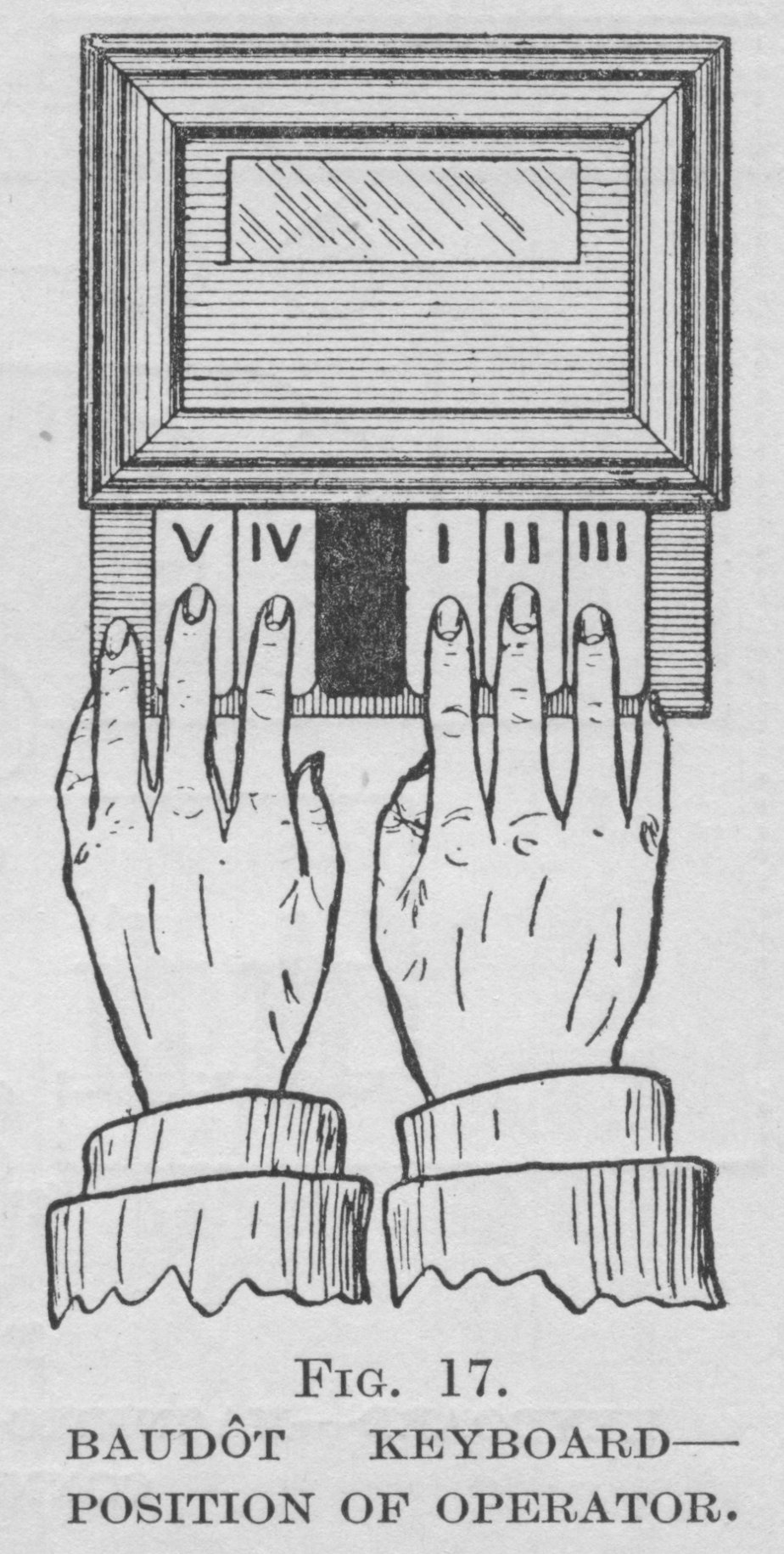
The Baudôt system could multiplex because, unlike most earlier systems for printing (and even perforating) telegraphy it employed a fixed-length code with each character of code transmitted by machine. (The multiplexing system could therefore more easily interleave the characters typed by multiple users onto a single line.) However, the keyboard upon which this code was produced had little to do with conventional keyboards. Here are two images of a Baudôt keyboard:

( Pendry, 1919. p. 40. The same image appears in Herbert (1920). p. 457, fig. 287.)
( Pendry, 1919. p. 41. The same image appears in Herbert (1920). p. 457, fig. 284.)
When I first saw a picture of this keyboard, I misunderstood it completely. As I was familiar with tape, and as I knew that Baudôt was a 5-level code, I immediately assume that this 5-key keyboard was a sort of direct tape perforator. It is not. In fact, perforated tape is not a part of the original Baudôt system at all.
The Baudôt code was indeed a 5-unit code. The five units of this code were transmitted serially on a single line. The Baudôt keyboard, however, allowed the operator to input all five units of the code at a single time. Basically (and simplifying), you pressed the keys down for the 5-unit combination and a rotating contact read the keypositions and transmitted the code. It was thus a direct code entry device, with the operator's brain providing the data processing facilities for translating the characters of the message into code combinations. This is crucial to understanding the code layout, because (as Herbert describes it) the arrangement of the code was done in order to make learning it as easy as possible:
"The five unit code first successfully used as a Telegraph code by Baudôt was allocated to the letters of the alphabet in a convenient order for easy learning. i.e., Keys 1, 2 and 3 were allotted to the vowels, while the consonants were formed in alphabetical order by the combination of keys 4 and 5 to the vowels, thus verification of a letter is always an easy matter. Unfortunately this arrangement does not suit typewriter keyboards, hence the reallocation of the alphabet in the Western Union and Murray duplex multiplex systems." Herbert 1920, p. 479 (PDF 506))
There are several ways to present Baudôt's code:
There are also two ways to present Baudôt's code which are not useful in themselves, but serve to illustrate what it is not:
Here is the entire code in its French version (as presented by an English writer in 1919), in alphabetical order:
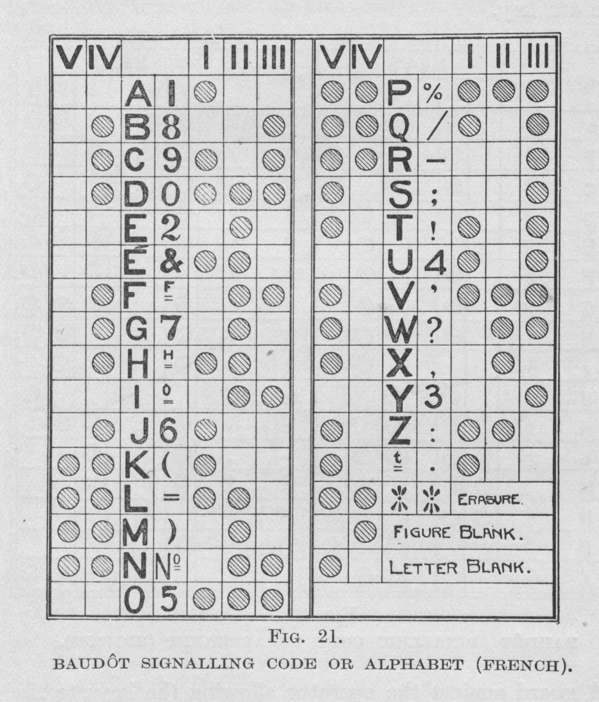
( Pendry, 1919. p. 43. This same figure appears in Herbert (1920). p. 457, fig. 284. However, in the online version on Google Books, it is difficult to interpret the figure (especially the superscript characters and "ERASURE".)
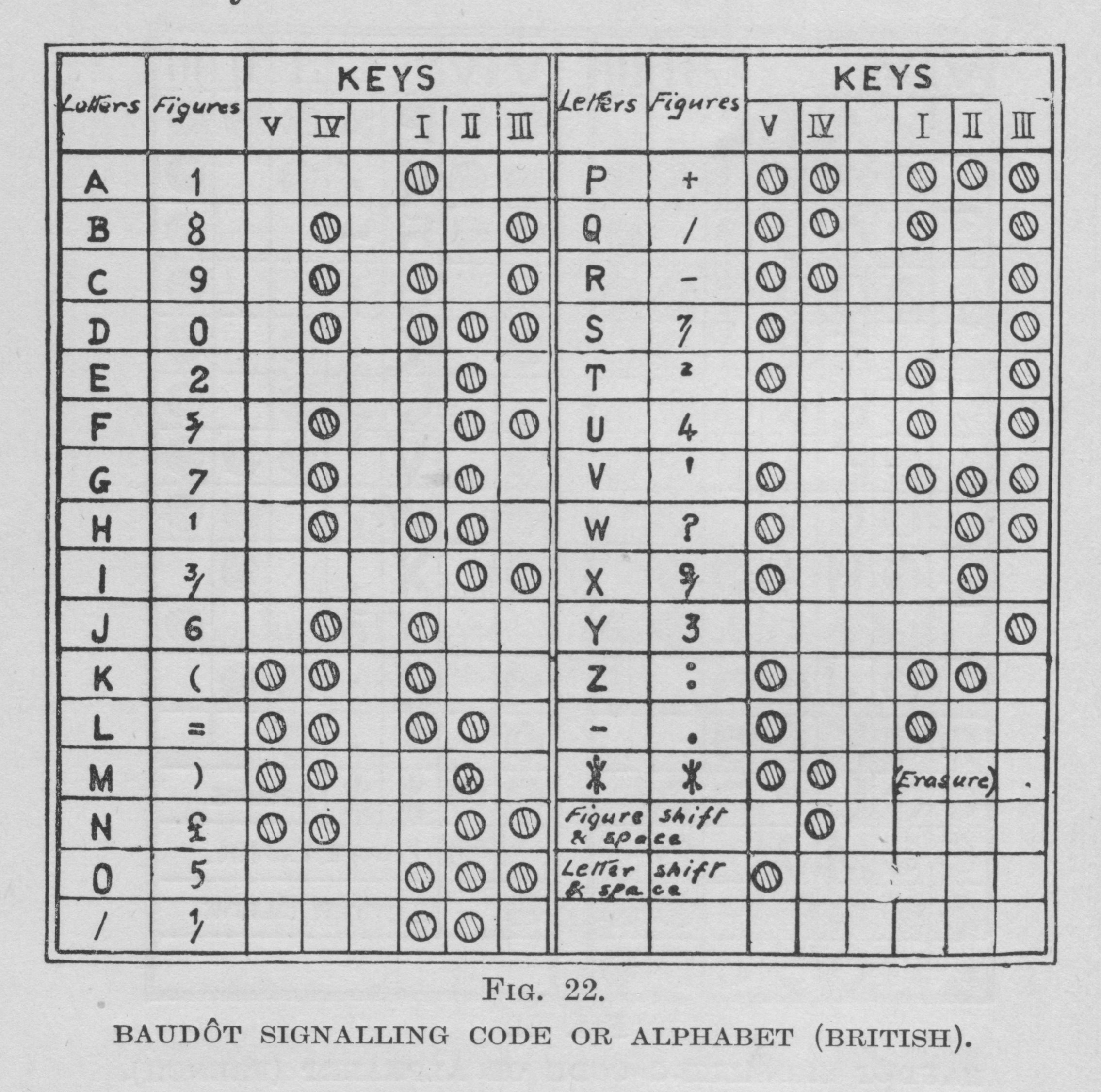
The English adopted a slightly different variation (primarily because they had no need for 'É', but with several other differences as well). Here it is from Pendry, 1919. p. 44.
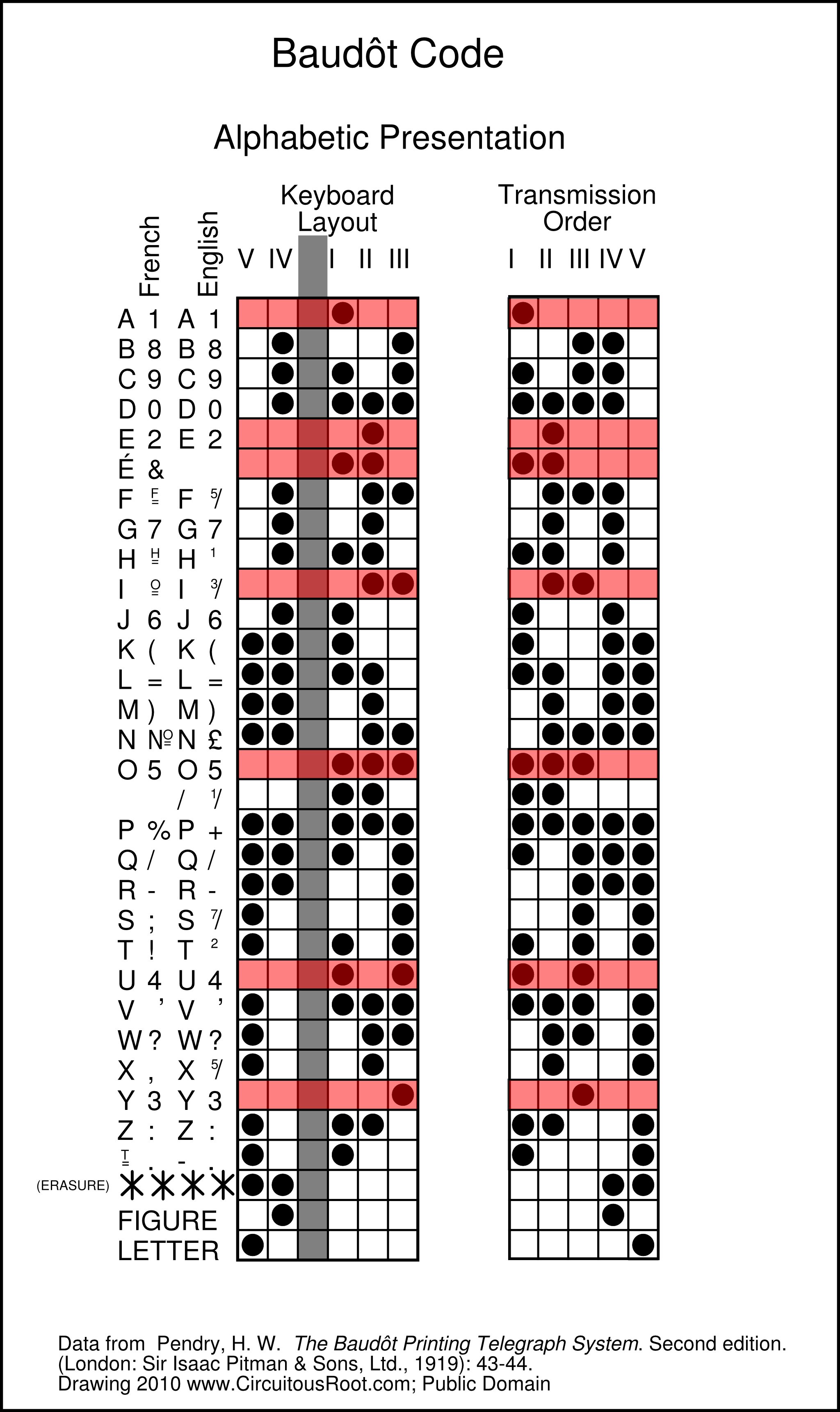
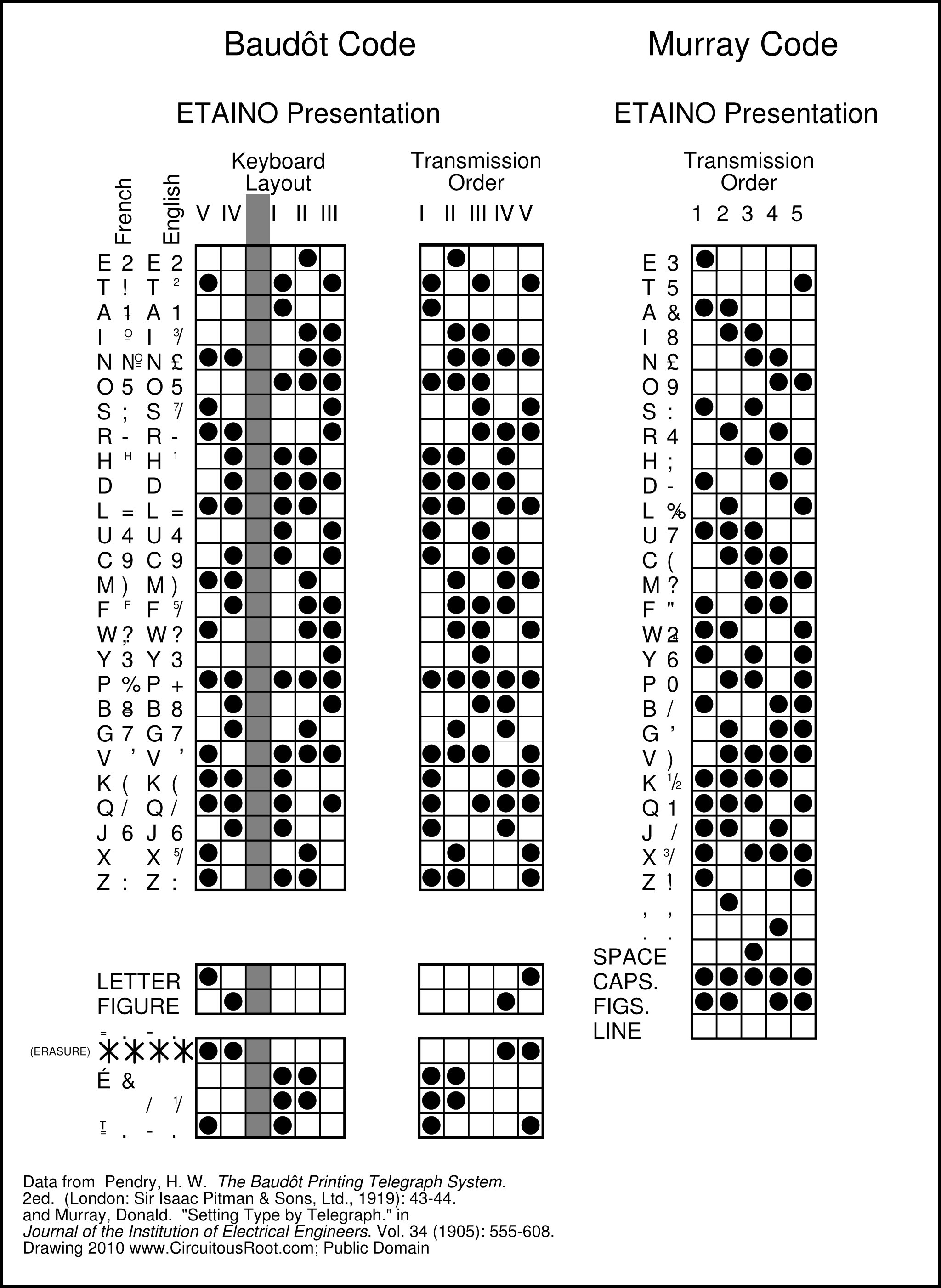
Here are the data, redrawn to show side-by-side the English and French versions, and the keyboard layout vs. the transmission order.
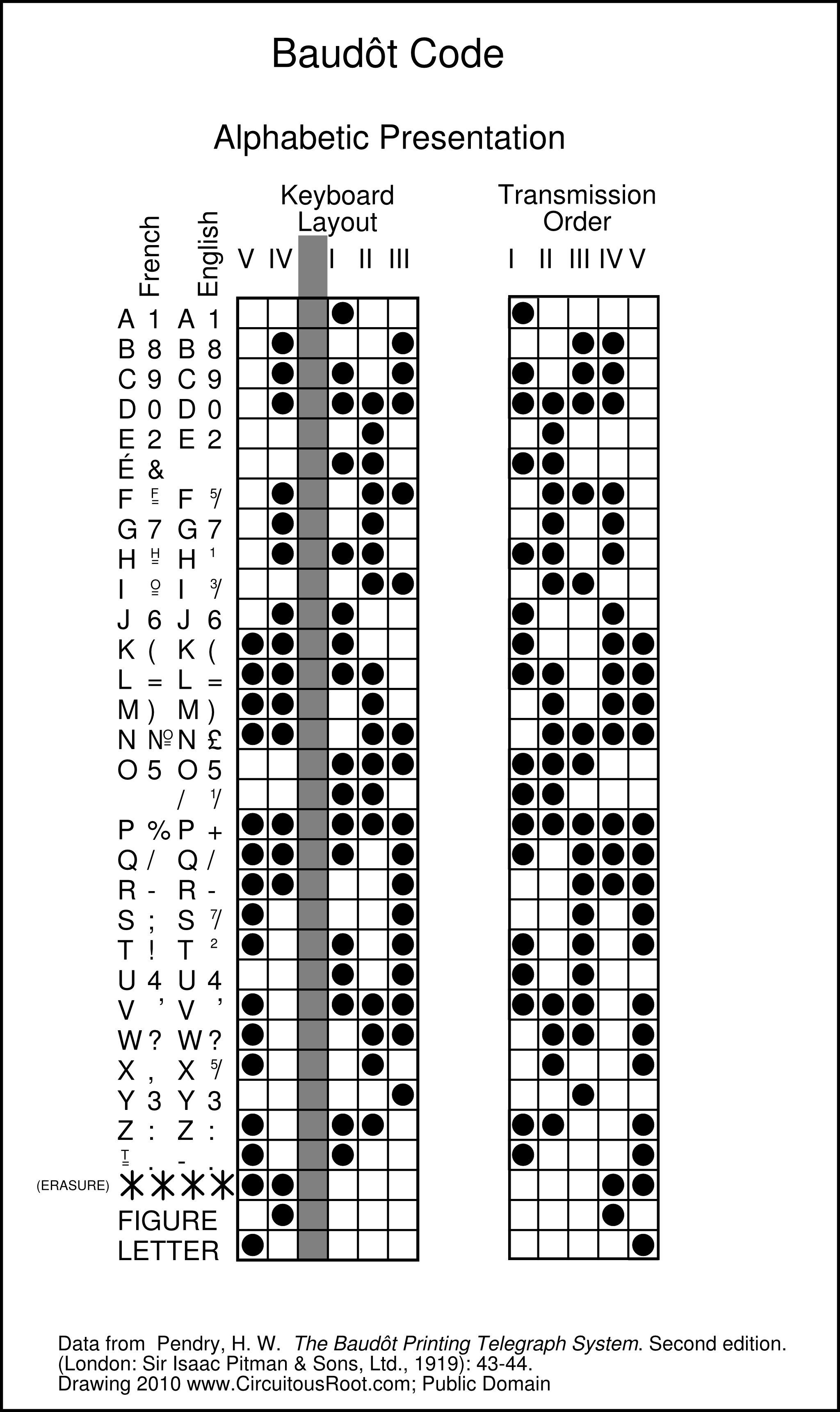
Here is a link to the SVG original of this drawing: baudot-alphabetic.svg This version may or may not render on your screen if you click on it. It might be useful, however, as a starting point for future versions (as it is the editable source for the drawing). Since it's all old, standard data drawn from public domain sources, and since the drawing itself is simple (though it did take a bit of care), I'm placing the drawing and its source in the public domain. The same is true of the other code charts I've done for this page.).
Analyzing this a little, here are the vowels (highlighted in red). Indeed, as Herbert explains, they use only the right hand, and no other characters use only the right hand:
(Here is a link to the source SVG file for this drawing , although it is nearly the same as the earlier one.)
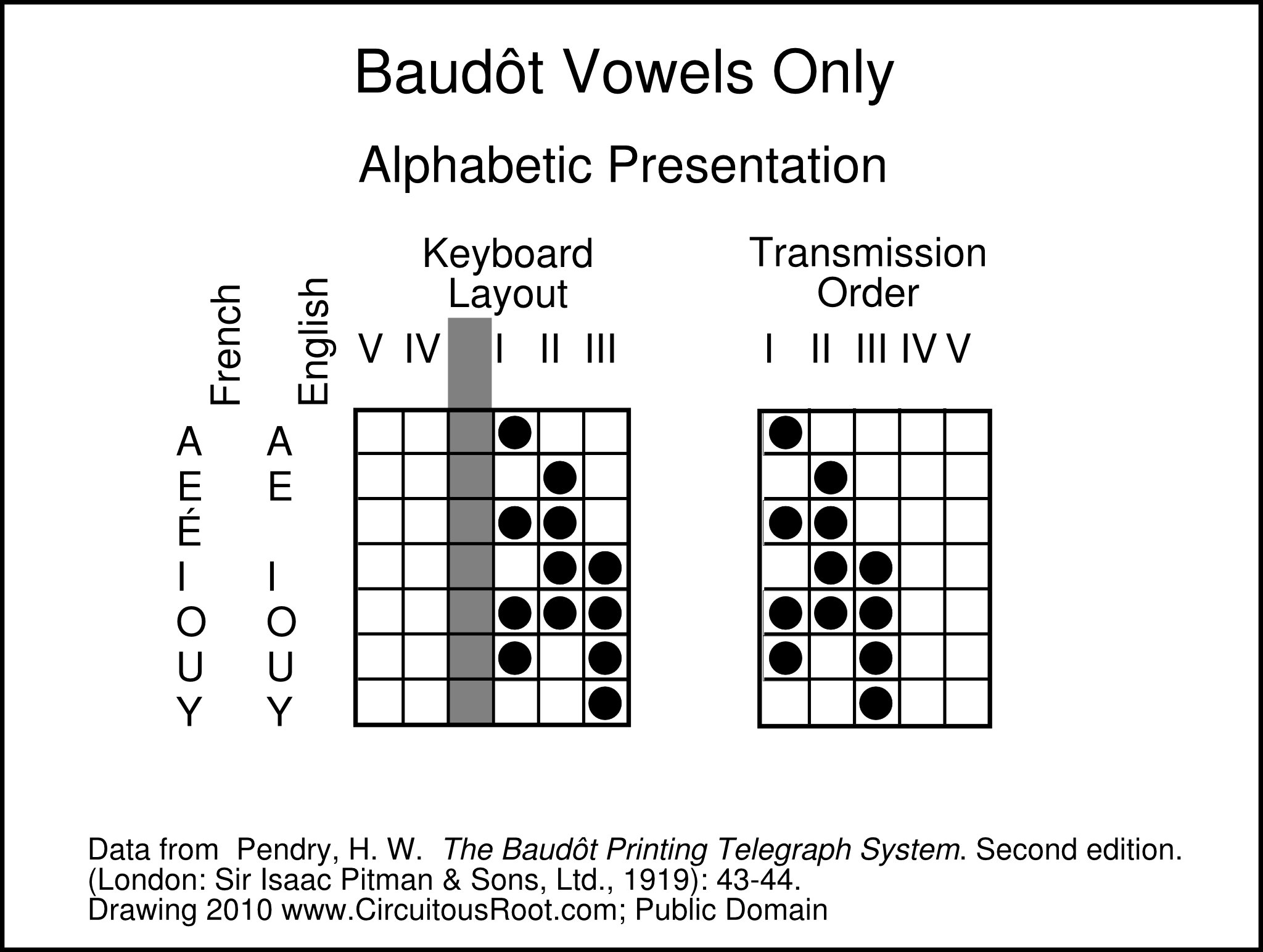
Here are just the vowels. They occupy only three positions I, II, and III (giving x^3 - 1 = 7 possible positions; Baudôt does not include an all-space code).
(The SVG source for this file is in the same file as the overall alphabetic presentation, baudot-alphabetic.svg.)
It is also clear from the chart above that for the consonants in alphabetical order the left hand follows a distinct grouping: B-J column IV only, K-R columns V and IV, and W - Z column V only. The pattern for the right hand within each grouping is perhaps less clear.
A part of it may be due, though, to the way in which the numbers are laid out. They follow a definite pattern, and also follow first the vowels (A - O), repeating this pattern with an additional unit in IV for the remaining numbers. It is clearly a pattern; it is also clearly a pattern unrelated to binary counting.

(The SVG source for this file is in the same file as the overall alphabetic presentation, baudot-alphabetic.svg.)
The numbering of the keys (V, IV, I, II, III) is curious, but might be explained by the significance of V and IV in forming the vowel/consonant patterns. IV alone is also the Figure Shift, while V alone is the Letter Shift.
Pendry (1919) is quite clear as to the order of the transmission of the signals on the line:
"The peculiar order of the numbers of the keys msut be noted, and, as it is the regular practice to indicate them by these numbers, any deviation therefrom would lead to confusion between stations. The signals pass to the line, it is true, in the order I, II, III, IV, V, and in the receiver the corresponding electro-magnets are arranged in that order, but the keyboard tappers are always put in the two groups, and numbered as indicated above." (p. 39)
Actually, the diagrams in the previous section have already shown Baudôt in transmission order. There is no need to repeat them here.
Before he even assings meanings to the code combinations, Pendry (1919) presents a "plan" (pattern) of the code (Fig. 4, on p. 11). In this, he he simply numbers the combinations.

To be honest, I can't figure out why he presents this "plan." He doesn't use it later. It isn't the alphabetical arrangement (in either keyboard or transmission order). It isn't the arrangement on the Type-Wheel (see below). It certainly isn't binary.
Here it is lined up with the alphabetic arrangements:
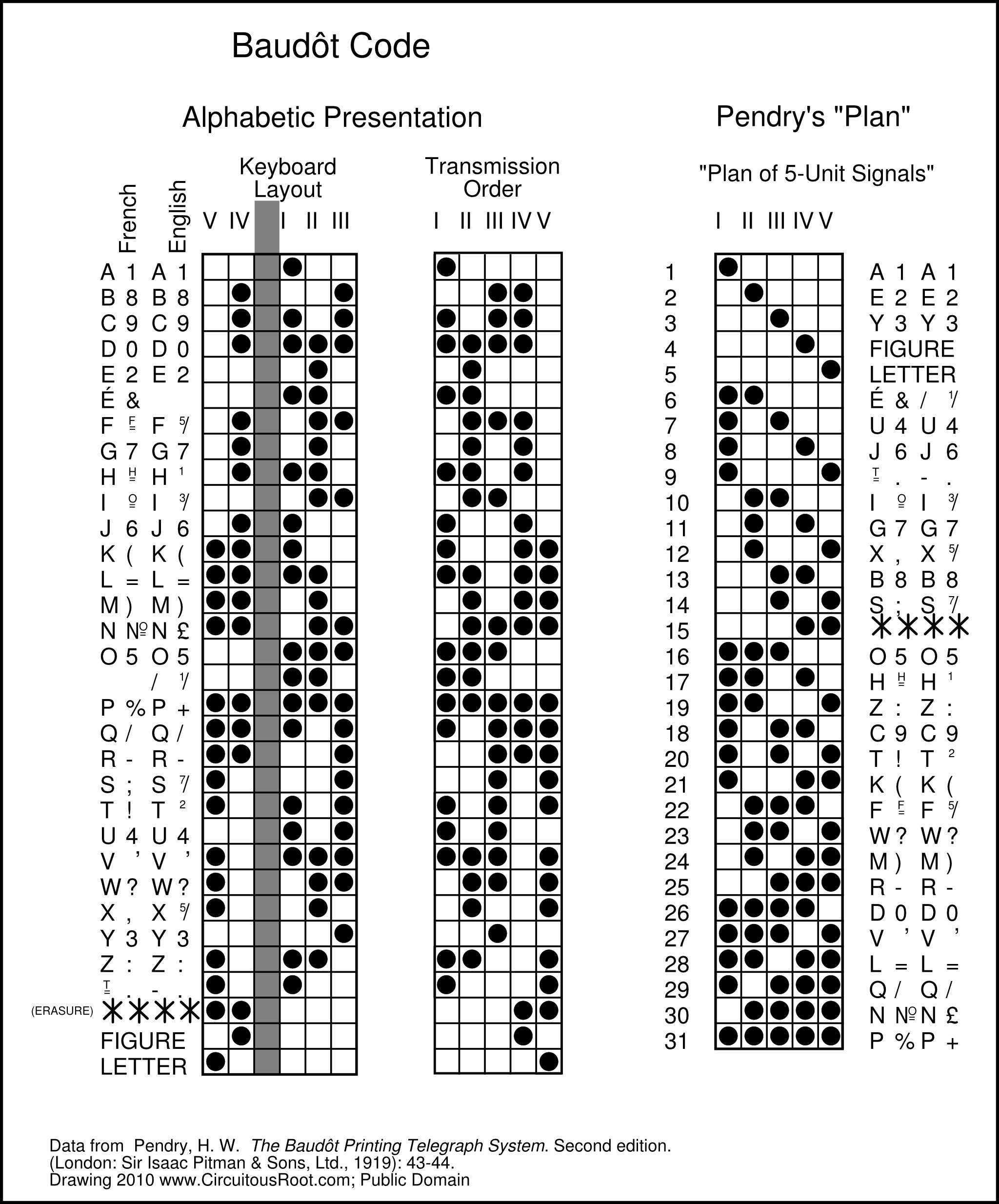
Here is a link to the SVG original of this drawing: baudot-pendry-plan.svg
The Baudôt code was received by a printing apparatus which employed for its printing a type-wheel with relief type on its periphery. The order of the type along this wheel was determined by an exceedingly clever coding arrangement on two intermediate decoding wheels (one for detecting all of the spacing units in a character and the other for simultaneously detecting all of the marking units). This isn't really the place to go into detail about this mechanism, but the resulting pattern is quite beautiful. Basically, Baudôt invented a shift register.

Here is a link to the SVG original of this drawing: baudot-type-wheel-2.svg
As noted, the Baudôt system did not involve punching tape. It printed to tape, but that was a visual output medium. It did not record data to tape.
Herbert (1920, p. 478, PDF 505) notes that one Carpentier (of Paris) did develop an input device based on a conventional keyboard which punched Baudôt code on a tape that could then be fed into a transmitter. He does not indicate whether a reperforator was developed.
It is interesting that Herbert refers to this tape as "cross-perforated" (p. 479). While someone raised on Teletypes might think of this as just ordinary punched tape, Murray's punched tape (see below) was punched linearly along the tape.

So by at least 1887 we had 5-Level encoding running across sprocket-fed tape, input from a standard (French) keyboard. However, the encoding scheme was determined not by that keyboard, or by tape, perforating, or printing considerations but by the ease of learning the code combinations when entered on the original 5-key Baudôt keyboard.
A computer programmer, trained on the powers of 2, would naturally think that a 5-unit code such as Baudôt's would have 2^6 = 32 states. In fact, however, Baudôt is a 31-state code.
In a communications system where the individual code characters can be clearly distinguished both from each other and from the line's resting state, then, indeed, a 5-unit code would be a 32 character code. However, this ability was only introduced with Krum's invention of start-stop coding for the Teletype. The Teletype is an isochronous system; that is, the transmitter and receiver must run more or less at the same speed within each character, but need not maintain synchronism between characters. Each "start" pulse resets the system.
Previous systems, including Baudôt's, were (imperfectly) synchronous rather than isochronous. That is, they required the transmitter and receiver to run at exactly the same speeds at all times. Since this was of course impossible, Pendry (for example) notes the techniques used to detect speed differences so that the machinery could be adjusted more or less constantly. ( Pendry, 1919, p. 3 for the manual correction of the Hughes system, and pp. 27-32 and 96-97 for the automatic correction of the Baudôt system).
In any system where the start of the transmission of a character is indicted by assumed timing rather than by a distinguishing event, if the system is normally spacing it is impossible to distinguish a fully-spacing character from the idle state of the line, and if the system is normally marking it is impossible to distinguish a fully marking character from the idle state of the line. The Baudôt system as employed by the British Post Office (at least) was normally spacing. There is therefore no all-space character in the code. (Indeed, the diagram of the code in Pendry, reproduced in Hausman, shows a 31 position code with no fully spacing character.)
It is almost impossible for a programmer such as myself not to think of a pattern of dots as a binary number. Baudôt's code is, however, resolutely not binary. Here's a version of the chart of the code with an additional column arranged in binary order (using the transmission order). This ordering corresponds to none of the rational orders for the code (not the alphabetic, or the type-wheel, or even Pendry's curious "Plan"). Baudôt is not binary.
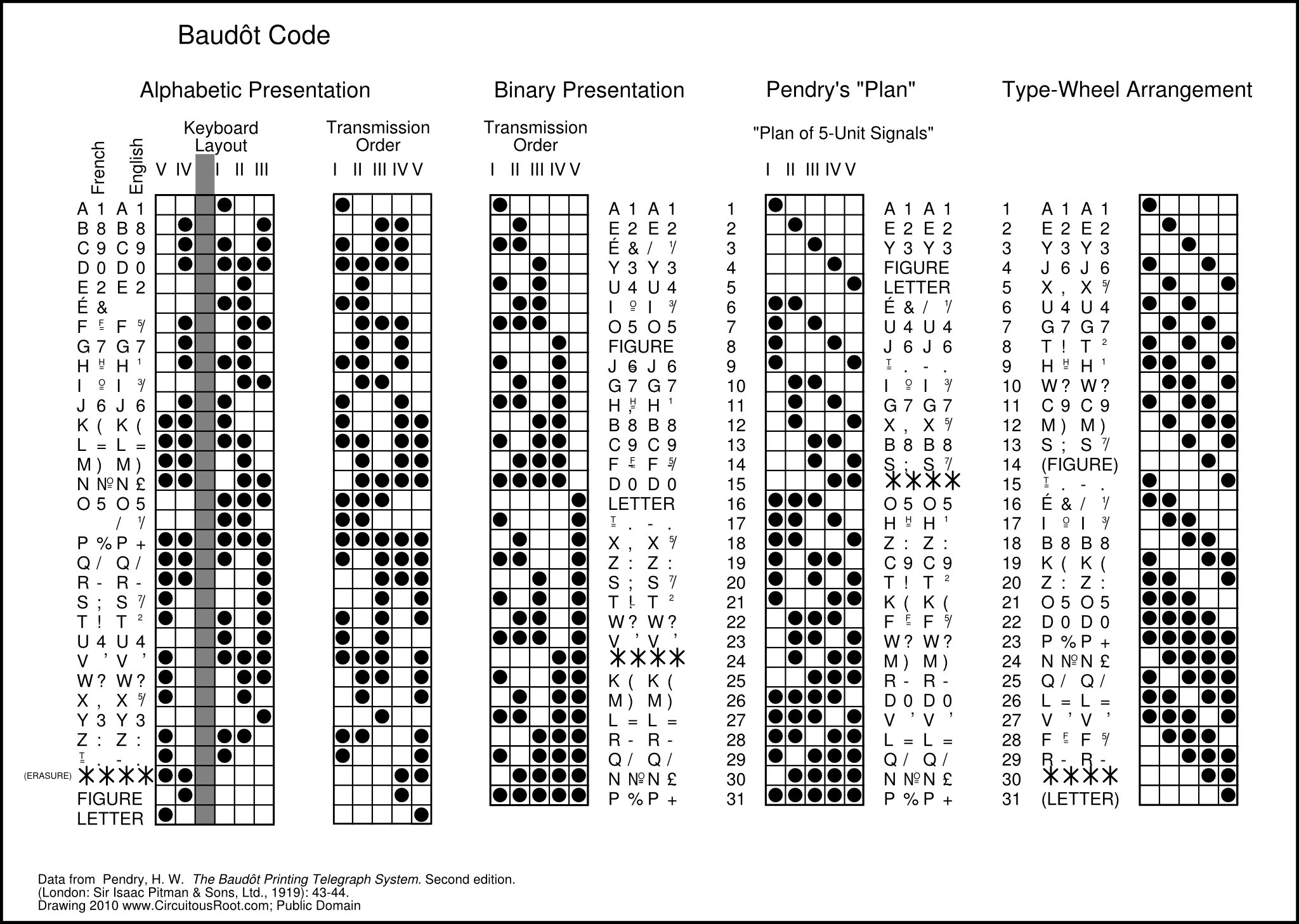
Here is a link to the SVG original of this drawing: baudot-binary.svg
I would like first to thank Heather Heywood, Head of Archive Services for the International Telecommunications Union. She was exceedingly helpful in tracking down the first occurrance of the alphabet associated with ITA-1, confirming the first specification of the signal encoding of ITA-1, and, most importantly, discovering the committee report and dates at which ITA-1 was deleted. Her assistance in particular, and more generally the work of the ITU Archives to document ITU history, have been invaluable to my research.
I should also emphasize that even though they have been very helpful, neither the ITU nor the ITU Archives endorses or bears any responsibility for the present document.
The simplest way to put it is that Baudôt's code was standardized into the International Telegraph Alphabet No. 1 (ITA-1). In practical terms, since ITA-1 isn't used even among most teleprinter enthusiasts today, knowing this is sufficient.
However, there seems to be a certain amount of partial information, or sometimes misinformation, concerning the origins of ITA-1 (And sometimes a confusion over ITA-1 itself, as some websites even claim that ITA-1 was Morse Code (which is entirely untrue.)) This present section is my attempt to piece together the history of ITA-1 using, primarily, the actual ITU standards and conference documents of the time. The secondary literature on ITA-1 simply is not reliable.
The ITU has an excellent history section of its website. Most of the documents cited here are available through this "History Portal." It is at: Welcome to History of ITU Portal : http://www.itu.int/en/history/Pages/default.aspx . The ITU-T (the current incarnation of the ITU's standardization "sector") also published in 2006 an interesting overview of its history (which also includes a general history of the ITU and of telecommunications generally): CCITT [and] ITU-T 1956-12006: 50 Years of Excellence .
The International Telegraph Union began in 1865. It is important to realize that it was a treaty-based organization which conducted its business through periodic conferences. Some of these were fully empowered, or "Plenipotentiary," conferences intended to revise the underlying treaty. Others were "Administrative" conferences intended to update and/or supply many of the actual operating details. For many decades after the founding of the ITU, these technical details concerned primarily issues of protocol (e.g., which telegrams get priority) and tariffs. What would now be termed "technical" standards entered into these documents gradually and slowly.
At a meeting in St. Petersburg in 1875, the ITU established both a new version of its governing treaty and a set of Telegraph Regulations. These Telegraph Regulations continued in force until 1932, with only administrative amendments accomplished through a series of Administrative Conferences. In 1932 the International Telegraph Union held a Plenipotentiary Conference, the International Telegraph Conference jointly with the International Radiotelegraph Conference. At this meeting, in Madrid, these two organizations merged into one: the International Telecommunications Union (also "ITU"). At this time a revised set of Regulations was issued which, again, continued with various revisions done at various Administrative Conferences over the years. [ Note 3-1] The subsequent evolution of these regulatory bodies and their regulations, especially since World War II, is complex and largely beyond the scope of the present discussion.
One clarification on the naming of committees is in order, however. As regulations became more complex and evolved into more technical standards, the work of making them moved increasingly to technical organizations. These have varied in name and structure over the years. Very briefly (and incompletely), the 1925 Paris (Administrative) International Telegraph Conference established two committees: the International Telegraph Consultative Committee (CCIT). and the International Long-Distance Telephone Consultative Committee (CCIF). These merged in 1956 into the International Telephone and Telegraph Consultative Committee, CCITT. The CCITT became the present "ITU-T" (ITU Telecommunications Standardization Sector) in 1993. [ Note 3-2]
As a technical aside, it is interesting to note that while the first Telegraph Regulations of 1875 were primarily procedural in nature, even at this date they contained some technical details of the type now to be seen in "standards" documents. For example, they defined the characters to be sent using either Morse Code or the Hughes telegraph system. They define the encoding of Morse characters and procedural signs, but not yet the encoding of characters for the Hughes system.
The first occurance of what was to become ITA-1 was in the Telegraph Regulations adopted in (Administrative) International Telegraph Conference in Lisbon (1908). This version of the Telegraph Regulations simply defined the characters which could be sent. It did not define their encoding. [ Note 3-3]
This entire section, tracing activities of a comittee established at the 1925 Paris Conference, may be a "red herring." I'll pursue it, though, because this committee has been cited in the literature as the origin of ITA-1.
The International Telegraph Conference held in 1925 in Paris was one such conference of the ITU in the period between 1875 and 1932 for the administrative revision of the Telegraph Regulations. In addition to simply revising the regulations, this conference also did several other things, including establishing the International Telegraph Consultative Committee (CCIT). It also established "a committee for the study of code langauges." [ Note 3-4])
As had been the case since the Lisbon conference of 1908, the 1925 Paris revision of the (St. Petersburg) Telegraph Regulations specified the characters to be transmitted in the Baudôt system but not the actual encoding of these characters. [ Note 3-5])
The Committee for the Study of Code Language (Comité d'étude pour le langage) apparently met "in Paris on 19 October 1925 and at Cortina d'Ampezzo (Italy) from 2-26 August 1926. There were also meetings in Washignton on 11 and 13 October 1927 and on the ocasion of the International Radiotelegraph Conference of Washington (1927)." [ Note 3-6 and Note 3-7])
There appears to be some confusion on the part of present readers (such as myself) as to what a Committee on Code Language might be studying. Authors such as Beauchamp, and others I've seen online who cite this committee's work, take the concept of "code language" to mean character encoding systems (such as Baudôt or Murray's 5-unit codes). However, as will become apparent in the discussion of the 1928 Brussels conference, below, this committee instead appeared to be studying the issue of the tariffs to be charged on telegrams sent using what in the US would be called "commercial codes."
The next Administrative Convention of the ITU was the International Telegraph Conference held in Brussels in 1928. The ITU notes that "... a protocol on code languages supplementing and amending the Regulations for international service was approved and signed." [ Note 3-7, again]) Yet the "Protocole portant additions et modifications au Réglement de service international. (Bruxelles, 1928)" as reprinted on the ITU History Portal does not address the encoding of characters. Rather, it addresses the issue of how to figure the prices to be charged for telegrams taking into account the use of "commercial codes."
From all that I have yet been able to discover in ITU historical documents, neither ITA-1 nor, indeed, any specification of the encoding of fixed-unit character codes existed as of the end of the 1928 Brussels conference.
[TO DO: Was the Committee on Code Language doing other work which did concern character encoding? What was the CCIT doing in this period? What, in general, was the technical activity which led to the adoption of ITA-1 in Madrid in 1932 (see below)?
The International Telegraph Conference of 1932, in Madrid, was a Plenipotentiary Conference (the first since St. Petersburg in 1875). It met simultaneous with the International Radiotelegraph Conference, and the organizations behind the two conferences deciced to join together into a single International Telecommunications Union (conveniently, also "ITU"). [ Note 3-8])
This Conference issued a new set of Telegraph Regulations, "annexed" (as more or less technical documents) to the (new) International Telecommunications Convention document itself. These Telegraph Regulations defined the character encoding of the International Telegraph Alphabet, No. 1. It is defined in Chapter IX ("Transmission Signals"), Article 35 ("Transmission Signals of the International Telegraph Alphabets Nos. 1 and 2, Morse Code Signals and Signals of the Hughes and Siemens Instruments"). This is pp 31-40 (ITA-1 chart on p. 33) of the official French version ( Règlement télégraphique annexé à la convention internationale des télécommunications - protocol finale audit règlement - Madrid, 1932 . (erne: Bureau Internationale de L'Union Télégraphique, 1933.) ]) The only official version was the French language one, but in London the General Post Office prepared a version with a translation into English ( Telegraph Regulations Annexed to the International Telecommunication Convention - Final Protocol to the Telegraph Regulations - Madrid 1932 . (London: His Majesty's Stationary Office, 1933.) ) The ITA-1 table appears on (English) p. 34 of this English translation.
This is the earliest definition that I have been able to discover in any document of official standing of something named the "Alphabet Télégraphique International No. 1" or of the signal encoding of ITA-1.
Still, questions about it remain unresolved. In particular, what was the technical activity behind its adoption? What committee studied and recommended it? The CCIT? The Committee for Code Langauge? Another? It is possible that the answers to this are in the "Documents" of the conference. These are online at the ITU History Portal [ Note 3-8, again], but are in French (a language I cannot read).
The next International Telegraph and Telephone Conference was an Administrative one, in 1938 in Cairo. The Telegraph Regulations adopted there retained the definition of ITA-1. It is defined in Chapter IX ("Transmission Signals"), Article 35 ("Transmission Signals of the International Telegraph Alphabets Nos. 1 and 2, Morse Code Signals and Signals of the Hughes and Siemens Instruments"). This is on p. [ Note 3-9], of the official French version and p. 36 of the unofficial English translation prepared by the General Post Office, London. [ Note 3-10],
In 1947, the ITU met in Atlantic City in a Plenipotentiary Conference. At this conference, they began the process of joining with the United Nations. The documents resulting from this conference were organizational rather than technical, however. Where the 1875 St. Petersburg Conference and the 1932 Madrid Conference issued both an international Convention and also Regulations, the Atlantic City issued a Convention only, without detailed Regulations. [ Note 3-11],
It is perhaps interesting to observe that in the period from 1865 through World War II the structure of the ITU was relatively stable, with more Administrative conferences to tune details than Plenipotentiary conferences to change institutional structures. Since then, however, the ogranization has undergone relatively rapid change, resulting in more Plenipotentiary conferences than Adminsitrative ones (and more recently the technical work once done at Administrative conferences has been moved into committees).
The next Administrative Conference, in 1949 in Paris, supplied the Regulations not present in the 1947 (Atlantic City) Convention. These remained similar in form to earlier Regulations (indeed, to those going back to the 1875 St. Petersburg Regulations). They retained ITA-1. IT is in chapter IX ("Transmission Signals"), Article 34 ("Transmission Signals of the International Telegraph Alphabets Nos. 1 and 2, and Morse Code Signals and Signals of the Hughes and Siemens Instruments."), which is p. 37 of both the English and French versions). [ Note 3-12],
In 1952 the ITU met in Buenos Aires in a Plenipotentiary Conference. As was the case with the 1947 Atlantic City Conference, the Buenos Aires Conference resulted in a new Convention only, without detailed Regulations. [ Note 3-13],
The next Administrative Conference was in 1958 in Geneva (not to be confused with a 1959 Plenipotentiary Conference also in Geneva). In looking at the history of the ITU, this Conference seems in a way to be the last of the older style of Administrative Conferences. Things changed structurally after this.
The 1958 Geneva Conference issued Telegraph Regulatiosn which retained ITA-1. It is defined in Chapter VI ("Transmission Signals"), Article 16 ("Transmission Signals of International Telegraph Alphabets Nos. 1 and 2, and Morse Code Signals"), which is pp. 12-21 (ITA-1 chart on p. 14) of both the French and English versions. [ Note 3-14],
The ITU met again in Plenipotentiary Conferences in 1959 (Geneva), 1965 (Montreaux), and 1973 (Malaga-Torremolinos). In each case, a new version of the International Telecommunications Convention emerged. This Convention itself was, as before, an organizational rather than technical document.
Meanwhile, the CCITT (International Telegraph and Telephone Consultative Committee) was meeting separately and discussing more technical matters. In the Fifth Plenary Assembly of the CCITT (Geneva, 4-15 December, 1972) "Study Group 1" reported that "as only five countries still used Alphabet No. 1 and intended to abandon it, it has been agreed [by Study Group 1] to delete the alphabet but to allow its use by bilateral agreement." (p. 64 of the CCITT Green Book, Volume I. (My thanks to Heather Heywood, Head of Archive Services for the International Telecommunications Union, for discovering this reference.)
Heather Heywood confirms that the Plenary Assembly of the CCITT accepted this recommendation and that ITA-1 was in fact removed at the World Administrative Telegraph and Telephone Conference (Geneva, 1973).
Note: This section really isn't relevant to ITA-1, since they were deleted in 1973 on a decision taken in 1972. However, the changes in ITU organization discussed here are useful in finding the location of ITA-2 (which is still in effect). You won't find it in a set of Telegraph Regulations adopted at an Administrative Conference and annexed to a treaty, though.
In the system in place until 1973, an International Telegraph/Telecommunication Convention would have had a set of Telegraph Regulations annexed to it, either at the Plenipotentiary Conference itself or at subsequent Administrative Conferences. For ITA-1, this had happened in 1932 (Madrid - but at a Plenipotentiary Conference), 1938 (Cairo, Administrative Conference), 1949 (Paris, Administrative Conference), and 1958 (Geneva, Administrative Conference). However, at some point after 1958 the technical workings of the Telegraph Regulations were separated from the Regulations themselves. I'm not sure exactly when this happened, but it may have been the next Administrative Conference after 1958, the 1973 World Administrative Telegraph and Telephone Conference in Geneva. [ Note 3-15]. The Telegraph Regulations contained in the Final Acts of the World Administrative Telegraph and Telephone Conference (Geneva, 1973) open with a "Note by the I.T.U. General Secretariat:
"The detailed provisions concerning the operation of the international public telegram service, hitherto contained in the Telegraph Regulations, will now be incorporated in the Instructions for the Operation of the International Public Telegram Service." (p. ii)
The remaining Telegraph Regulations document is rather short and very general; many of its provisions simply refer to the CCITT.
The new task in tracing the history of telegraph standards becomes at this point finding the "Instructions for the Operation of the International Public Telegram Service." This task is more complex since the institutional structure at the ITU responsible for these Instructions has changed since 1973.
According to the WorldCat international library catalog, a document entitled Instructions for the Operation of the International Public Telegram Service was indeed published in 1974. Another version was published in 1977 . I have not yet obtained either document.
At some point, these Instructions became a part of the current structure of Recommendations of the ITU (now more specifically the ITU-T (the ITU Telecommunications Standardization Sector). It is now Recommendation F.1 ( Operational Provisions for the International Public Telegram Service ). According to the ITU, the editions of Recommendation F.1 are:
Only versions from 4 (1988) onward are available online from the ITU.
However, a study of versions of this Recommendation from Edition 4 (1988-11) through the current version (1998-03) is revealing. It is very, very similar in structure and content to the old Telegraph Regulations. It, along with Recommendations F.2, F.4, F.10 and F.11 might be considered the heirs of the old Telgraph Regulations. The current version of F.1 (1998-03) makes reference to ITA-2 (defined in ITU-T S.1, International Telegraph Alphabet No. 2 ).
[TO DO: Track down "Instructions for the Operation of the International Public Telegram Service" (1974, 1977) and Operational Provisions for the International Public Telegram Service (ed. 1 (1976), 2 (1980), and 3 (1984))]
Summary: The International Telegraph Alphabet No. 1 came into existence at the 1932 International Telegraph Conference (where, also, the International Telegraph Union and the International Radiotelegraph Conference merged to form the International Telecommuniations Union). It was reaffirmed in Telegraph Regulations through the 1958 ITU Administrative Conference, Geneva. In 1972, the CCITT recommended that it be deleted, and in 1973 it was.
The simplest statement would be that ITA-1 is, indeed, based on Baudôt. But there are some interesting differences.
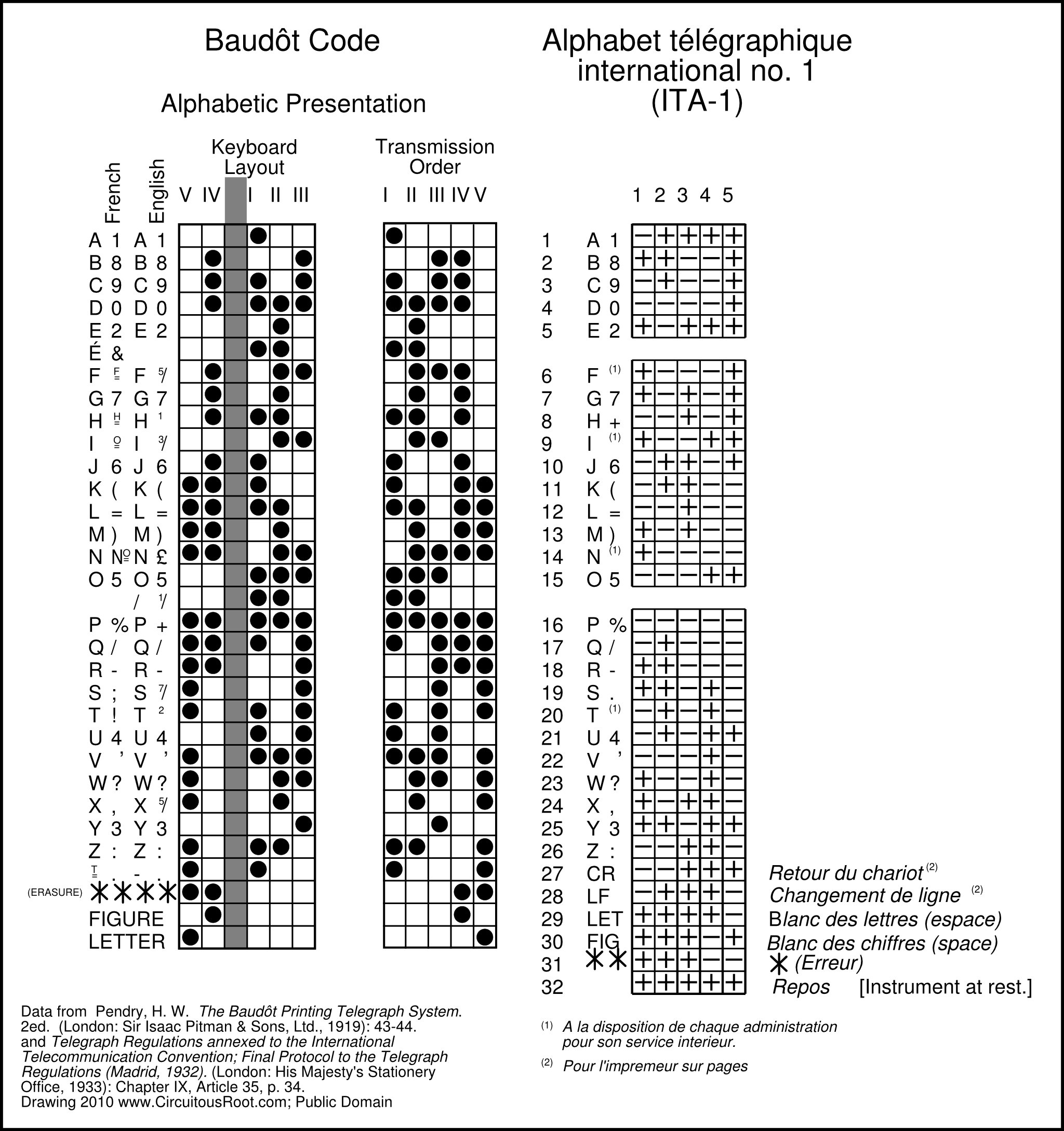
Here is a link to the SVG original of this drawing: ita-1.svg
Perhaps the most interesting difference is the provision of Carriage Return and Line Feed characters in ITA-1, taking over for 'É' and superscript-T in Baudôt. The Baudôt apparatus was tape-printing, not page printing. Yet ITA-1 contains the two codes necessary for page printing, and the standard refers explicitly to page printers. I do not know whether any ITA-1 page printers were ever made.
The next curious thing about ITA-1 is that it is specified in terms of a polar telegraph system (negative and positive currents). The negative current corresponds to a "mark" and the positive to a "space." This is particularly curious as in the same document ITA-2 is specified for both neutral systems (no current and (specifically) positive current) and polar systems (negative current and positive current) and in both neutral and polar operation positive current corresponds to "mark." Moreover, Pendry (1919, p. 99) suggests that the system of operation familiar to him was polar and used positive current for "mark" and negative for "space."
So, technically, a neutral system or one using negative current in any capacity for "space" cannot be using ITA-1. Indeed, ITA-1 as defined is not backward-compatible, electrically, with the Baudôt systems described by Pendry (though of course I doubt anyone would have been so fussy). The curious thing is that they were so specific about it in this way. This suggests to me that they might simply have been thinking of some particular machine.
Other than that, ITA-1 seems a pretty direct extension of Baudôt. All of the letters and numbers line up. Most of the less-common FIGURE-shifted symbols have been left for private use. Even though it lists 32 code positions, it is still a "31 bit" code insofar as the final position is not an explicit signal but rather simply the state of the instrument being "at rest."
While there were several other printing telegraph systems in the period (some relatively successful), the next one which enters into this present discussion is that of Donald Murray.
Murray was active for an extended period, but the 1905 version of his apparatus looked like this:
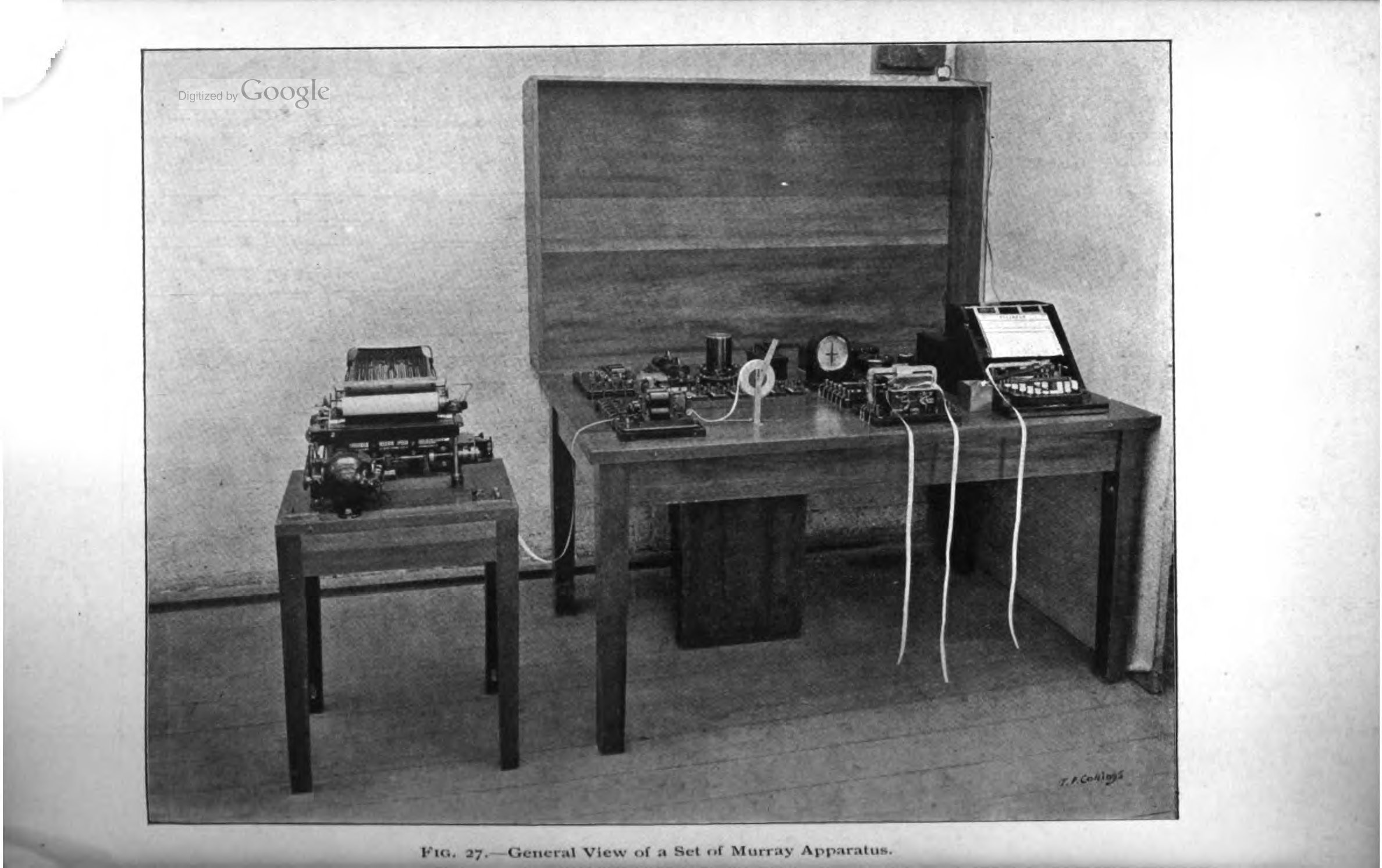
("Setting Type by Telegraph" in Journal of the Institution of Electrical Engineers . Vol. 24 (1905): 566, PDF 601)).
Several of the functional units shown will be more or less familiar to a Teletype operator. There is a keyboard perforator on the right. (I'm not entirely sure yet, but I do not think that it included a transmitter; this is not a KSR.) The next unit to its left, with tape hanging down from both sides, is the "single line transmitter." In Teletype terminology, I think that this would be much like a "Transmitter-Distributor." The apparatus to the rear of the table looks like telegraph equipment (for this demonstration setup); the cylindrical object look a lot like a line relay. On the left of the table is what would be called a Reperforator in Teletype terminology: a unit to receive a signal and punch it to tape. This tape is then fed into a page printer on a separate table.
Here's a closer look at the keyboard perforator, with its cover removed:

It is clearly a QWERTY keyboard, though it has been rearranged just enough to drive a touch typist mad:
What is most interesting, though, is the tape. It is punched longitudinally along the tape, not across the tape:
Murray's code was also a fixed-length, 5-unit code. Murray's system was also a synchronous system (like Baudôt's) rather than a start-stop system (like Krum/Morkrum/Teletype after 1919). The actual character encoding of Murray's code differed entirely from that of Baudôt, however. Here is Murray's own presentation of his code and Baudôt's, in 1905. Column B represents Murray code as punched on tape. Column C represents Murray code as transmitted on what we would term a neutral line. Column E represents the same Murray code transmitted on what we would call a polar line ("the alternating current"). Column D is Baudôt, represented in transmission order.
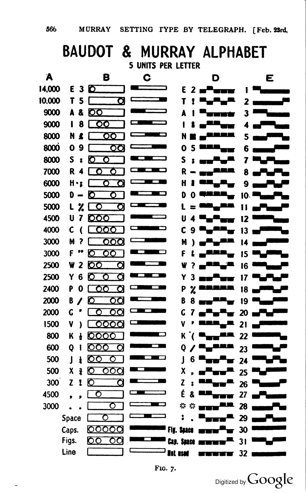
("Setting Type by Telegraph" in Journal of the Institution of Electrical Engineers . Vol. 24 (1905): 566, PDF 601)).
Here are the two codes presented side-by-side, alphabetically, in a new chart:
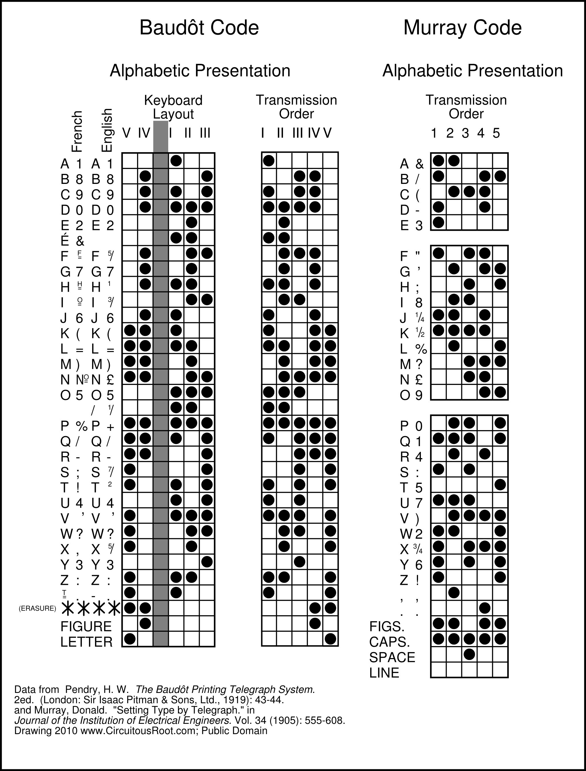
Here is a link to the SVG original of this drawing: murray-alphabetic.svg
It is clear that Murray's code and Baudôt's code are different. Column A of Murray's chart gives the clue as to why (well, it isn't a "clue" as such; it's something that Murray makes a point of). Murray's code is arranged in such a way that the number of punches is fewest for the most frequently used letters of the alphabet. (He uses "ETAINO SRHDLU", while Mergenthaler in the 1880s used "ETAOIN SHRDLU".)
Murray says of his code, relative to Baudôt's, that "The only difference is in the allotment of the letters to the various permutations, the Murray arrangement being designed to punch as few holes as possible in the tape." (Murray, 1905, p. 567 (PDF 602)).
In other words, because Murray was using a conventional keyboard from the start, he could let the keyboard machinery do the encoding translation (not the operator, as in Baudôt's 5-key keyboard). He therefore designed his encoding to minimize wear on his tape punch. This wear would have been five times that of a Teletype punch, because his tape was punched linearly and had to use a single punch serially, rather than five punches in parallel.
One other aspect of this system becomes apparent upon inspection: Murray's keyboard is QWERTY. This can be determined by reverse-engineering the numbers: Q/1, W/2, E/3, R/4, T/5, Y/6, U/7, I/8, O/9, P/0.
Here is the Murray code, in "ETAINO" order, with Baudôt's in the same order for comparison (just to see that it is not, in fact, the same).
Here is a link to the SVG original of this drawing: murray-etaino.svg
One puzzle remains for me with Murray's code, however: although the Murray system included a page printer, the code does not include Carriage Return or Line feed characters. Clearly some method of generating newlines was provided, as in "Setting Type by Telegraph" (1905) Murray writes "[at the end of a line] A key is then depressed which punches a line signal on the tape. [which causes a carriage return and a line-feed on printing]" (p. 501, PDF 632) What this "line signal" is is not clear to me at present.
The use of the name "Baudôt" has historically been quite confusing. The code developed by Baudôt was used on tape-printing telegraph systems. It was formalized into ITA-1 with additional codes designed for page printing systems. However, it was never used on start-stop telegraph transmission systems as introduced by Krum for the Morkum/Teletype page-printing equipment, and neither Baudôt nor ITA-1 was ever used on such equipment.
The code that was used on start-stop systems was that which was introduced by Murray, adopted by Morkrum/Teletype, and later standardized as ITA-2.
This seems simple enough. Howver, throughout the period of active use of Teletype systems, ITA-2 was commonly called "Baudôt." Indeed, even today any 5-bit code is often simply called "Baudôt," regardless of what it is. If you were writing a book about Teletype operators in the 20th century, you'd have to make your characters talk about "Baudôt" code in order to sound authentic, even though the code they were using wasn't Baudôt. [TO DO: There's at least one 1970s vintage Teletype manual that calls the code "Baudot" - find the reference.]
Murray himself may be the source of this confusion, although if so it would be better to say "the misunderstanding of what Murray said." Bear in mind that although the Baudôt system originated in the 1880s, it was French (and therefore more or less ignored in England). The 1906 edition of Herbert's Telegraphy, for example, doesn't even cite Baudôt in the index (although it devotes a chapter to the Hughes system). By the 1920 edition, of course, Herbert had to devote a chapter to Baudôt's system.
So when in a comprehensive 1905 paper on printing telegraphy, Murray notes: "Unquestionably the best alphabet for machine telegraphy is that used in the Baudôt and Murray systems," he was writing to an audience which might have had a limited familiarity with the Baudôt system. ("Setting Type by Telegraph" in Journal of the Institution of Electrical Engineers . Vol. 24 (1905): 564, PDF 599)).
Again, in 1910, Murray says of his own system that it uses "the Baudôt 5-unit alphabet." ("Practical Aspects of Printing Telegraphs." in Proceedings of the Institution of Electrical Engineers . Vo. 47 (1910): 498.))
However, it is important to realize what Murray meant by "alphabet" here. He might better have said "signaling system." Especially in his 1905 paper, he was discussing the differences between various types of telegraphic signaling sytems (Morse code, the Rowland system used by Siemens and Halske, the Buckingham system, Baudôt's, and his own.) The characteristic difference between these various other systems, on the one hand, and both his system and Baudôt's system, on the other hand, is that they employed either variable length encodings or very long fixed-length encodings. His system, and Baudôt's, employed the shortest practical fixed-length encoding. This is what he meant, I believe, when he said that his "alphabet" and Baudôt's were equivalent; not that they had the same patterns for the characters.
Yet from this initial confusion sprang a century of misleading colloquial vocabulary.
This present section is a puzzle. I haven't figured it out yet, so I'll just note it and skip it for now.
The argument to be developed below basically traces 5-unit telegraph code used by Teletype and formalized into ITA-2 back to its origins in an earlier code by Donald Murray. The early codes used by the Morkrum company (later to become the Teletype Corporation) are therefore important. The earliest document of which I am aware which presents the Morkrum code is a B.S. thesis by Ralph H. Earle in 1917, The Morkrum Printing Telegraph System . In it, he presents the code used by Morkum in 1917. (This would be just prior to the invention of start-stop transmission by Krum in 1919. The Morkrum equipment described by Earle is synchronous.) The puzzle is that the code he presents is not the same as the code used later by Morkrum/Teletype.
Here it is, from Earle's thesis. He presents it as a literal strip of paper tape, annotated by hand. The rows on the tape are not exactly square with the tape; this is due to characteristics of the equipment.
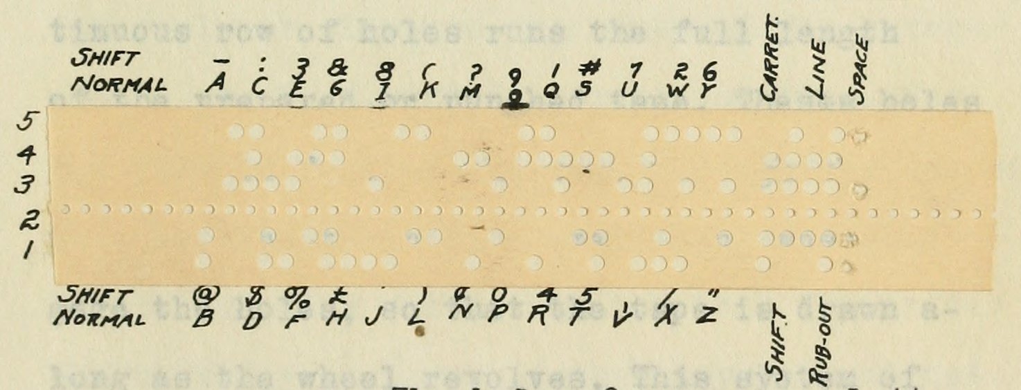
The code as presented above is neither Murray's nor Baudôt's.
At some point after 1917, Morkrum/Teletype changed the code they used to the code familiar throughout operation of Teletype and related 5-Level start-stop equipment. Unfortunately the earliest documents I have been able to find which specify this code date from 1931, over a decade after the 1919 invention of start-stop transmission and well into Teletype production (indeed, after the introduction of the 6-Level Teletypesetter in 1929). These documents are:
Teletype Bulletin 126, Issue 2 (December, 1931), Description: Type Bar Tape Printer Model 14 .
Teletype Bulletin 141 [presumably Issue 1] February, 1931. Description: Type Bar Page Printer Model 15 .
Here is a comparison of the codes they specify, in "ETAINO" presentation with Baudôt and Murray codes for comparison:
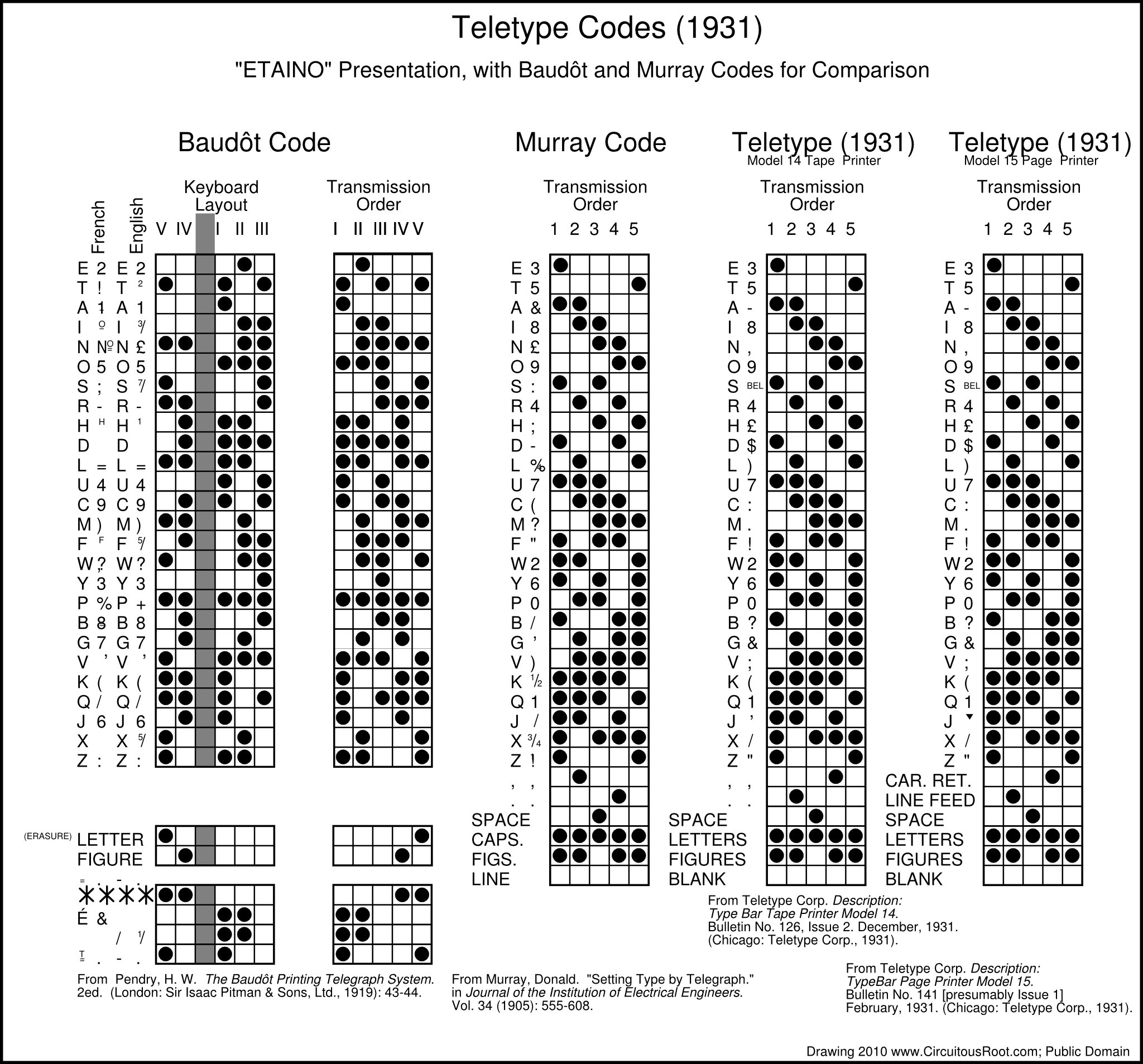
Here is a link to the SVG original of this drawing: morkrum-1931.svg
It is pretty clear that the Teletype 5-Level code is based on the Murray code, not the Baudôt code. That is, the principle of its arrangement is that of reducing the number of punches by assigning more common letters to code combinations with fewer punches, using exactly the same pattern as Murray. As is the case with Murray's code, the allocation of the digits is determined by the QWERTY keyboard's top row after the letters have been assigned.
The allocation of the non-numeric shifted characters is quite different in the Teletype code (vs. Murray), but this is to be expected. The only significant difference between the two codes is the curious inversion of the comma and period characters printed on Teletype tape printers in place of Carriage Return and Line Feed when considered in comparison with the corresponding characters in Murray.
This code is pretty much the standard 5-Level Teletype code common throughout the 20th century. Here is the Morkrum/Teletype encoding, presented with military thoroughness in the 1940s. The only difference is the substitution of "STOP" for the British Pound sign.
[United States] War Department Technical Manual TM 11-2222 Transmitter Distributors[,] Teletype Model 14. (Washington: U.S. Government Printing Office, August 1945).
I have not been able to discover any reference to either an International Telegrpah Alphabet No. 2 or to the character set transmitted by Murray, Morkrum, or Teletype instruments prior to the adoption of ITA-2 in the Madrid conference of the ITU in 1932. Prior editions of the Telegraph Regulations (through the 1928 Brussels (Administrative) Conference) defined only the character sets used for Morse Code and for the Baudót, Hughes, and Siemens instruments. The 1932 Madrid conference simultaneously issued a new International Telecommunications Convention (the first to bear the term "telecommunications") and a new set of Telegraph Regulations. These Telegraph Regulations defined both the characters and the signal encodings of ITA-2. [ Note 7-1],
Here is a chart of ITA-2. It is presented in "ETAINO" order so as to show the relationship between ITA-2/Teletype 5-Level code and the Murray code. The chart shows the Murray code (from his 1905 paper), the Teletype code as used in 1931, ITA-2 as originally introduced in 1932, and ITA-2 as it presently exists in ITU-T Recommendation S.1.

Here is a link to the SVG original of this drawing: ita-2-etaino.svg
Several things are clear from these charts. The US Teletype code is almost, but not quite, ITA-2. Most of the differences between them are accomodated in ITA-2 as characters definable by the "local administration" (for example, Figure-H and Figure-D (undefined in ITA-2, GB and US currency symbols in 1931 Teletype, and STOP and $ in later Teletype). The only difference between these two codes not accomodated by ITA-2 is the curious inversion of BELL and Apostrophe. Figure-S is Apostrophe in ITA-2 and BELL in Teletype, while Figure-J is "Signal acoustique" (Madrid, 1932) or "Audible signal" (Recommendation S.1) in ITA-2 and Apostrophe in Teletype.
Between 1932 and 1993, ITA-2 seems to have changed only in the clarification of details (and in the representation of signal states).
At the time of writing (2010), ITA-2 is still defined as an ITU standard. It is Recommendation S.1: International Telegraph Alphabet No. 2 in the S Series of ITU-T Recommendations ("Telegraph Services Terminal Equipment"). Recommendation S.1 is also referenced in Operational Provisions for the International Public Telegram Service. Recommendation F.1 in the F Series of ITU-T Recommendations ("Non-Telephone Telecommunications Services.")
The next code to consider is the 6-Level code designed for the Teletypesetter. The short answer here is that the Teletypesetter code seems to be a direct, and partially (but not entirely) backward-compatible, extension of the Teletype code. To really understand the Teletypesetter code, though, requires some background in the operation and features of the Linotype. (I am assuming here that you may know quite a bit about Teletypes, but not necessarily much about Linotypes. Experienced linecasting folks can skip this section.)
The Linotype is not a printer (it does not produce any printed output) and it is not a typesetter (it does not arrange or "set" individual relief printing types). Rather, it is a machine which produces as its output a "slug" or bar of typemetal which has cast upon it in relief the characters of a single line of type (hence the name, "line-o-type"; the "Lin-" in Linotype is pronounced "LINE" rather than "LYNN"). These slugs are then assembled (possibly after further sawing operations) into a page to be printed.
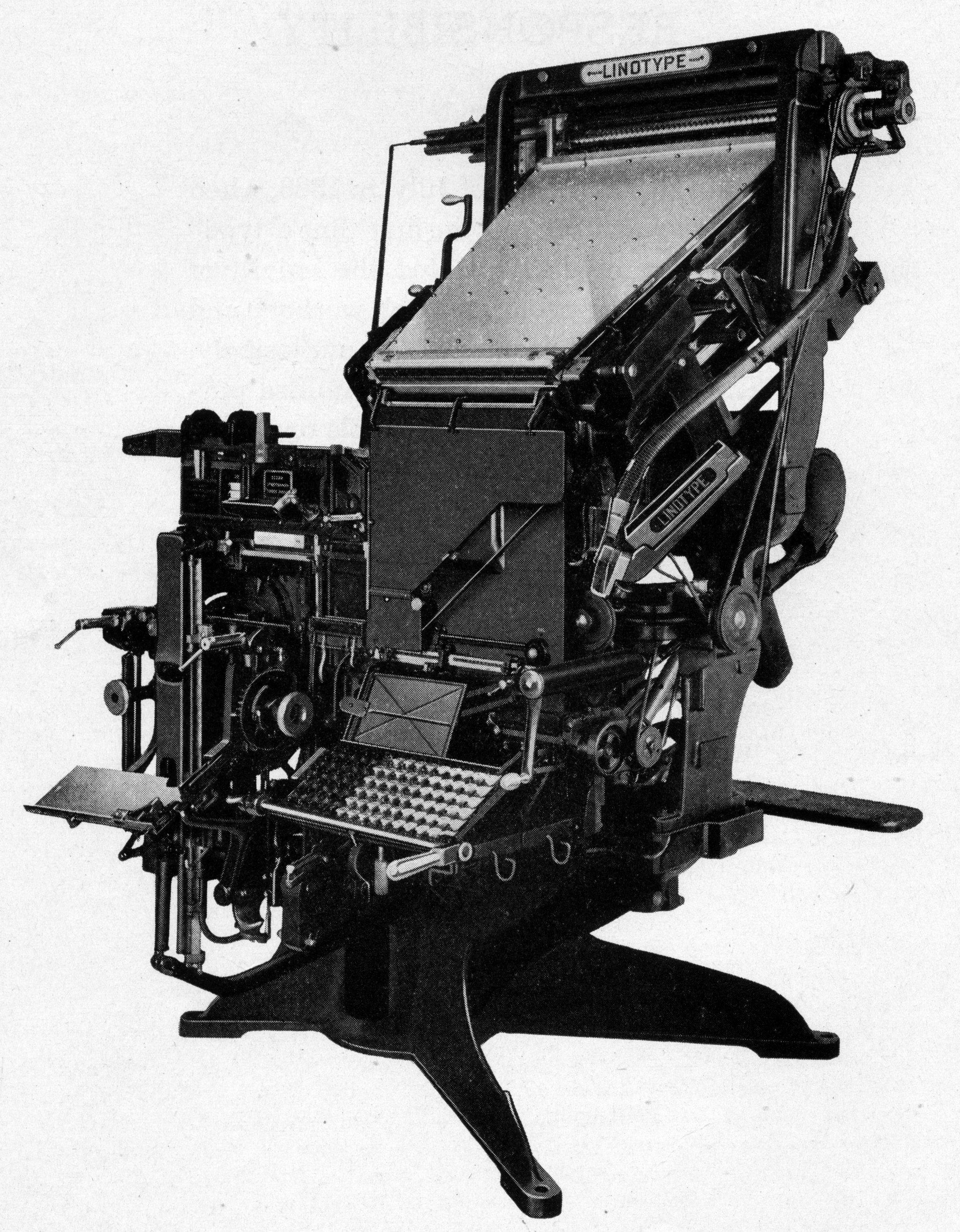
(From "The Big Scheme of Simple Operation." This was published in a number of forms, and incorporated into a number of other publications, by the Mergenthaler Linotype Company (Brooklyn, NY). The version from which the images here were scanned is a 1940 separate publication as a booklet.)
People in the Teletype world keep complaining about how heavy their machines are. Linotype enthusiasts have a different perspective. The Model 31 as shown would weigh somewhere around 3,400 pounds, depending upon features. The Model 31 was the standard Linotype model for manually set newspaper work and general jobbing from the mid 1930s through the end of production in the late 1970s. The machine shown here is not configured for Teletypesetter use (nor does it have a "quadder," a common accessory), but it serves to give a good general idea of what a standard Linotype looked like.
The Linotype was developed in the 1880s by Ottmar Mergenthaler and others. It emerged in substantially its modern form about 1890, and continued in production until the late 1970s. After the initial patents had expired, around 1913, a competing company, the Intertype Corporation, started to manufacture what would today be called a "clone" of the Linotype. For the purposes of understanding the Teletypesetter code, anything said about a Linotype applies to an Intertype as well. (There was a third competitor, the Linograph, which was a smaller, simplified machine. The Linograph company did not survive the second World War. To the best of my knowledge, the Teletypesetter was never applied to the Linograph (although I could well be wrong about this!))
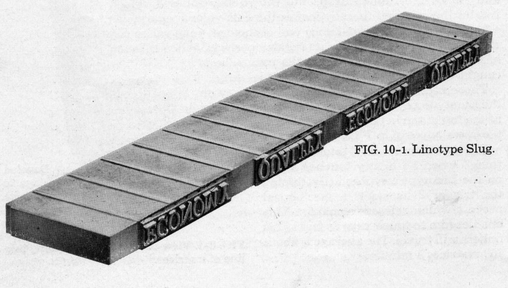
Here is an illustration of a Linotype slug. It is correctly read in the same way that all relief type is read: left-to-right, upside-down, as shown here:
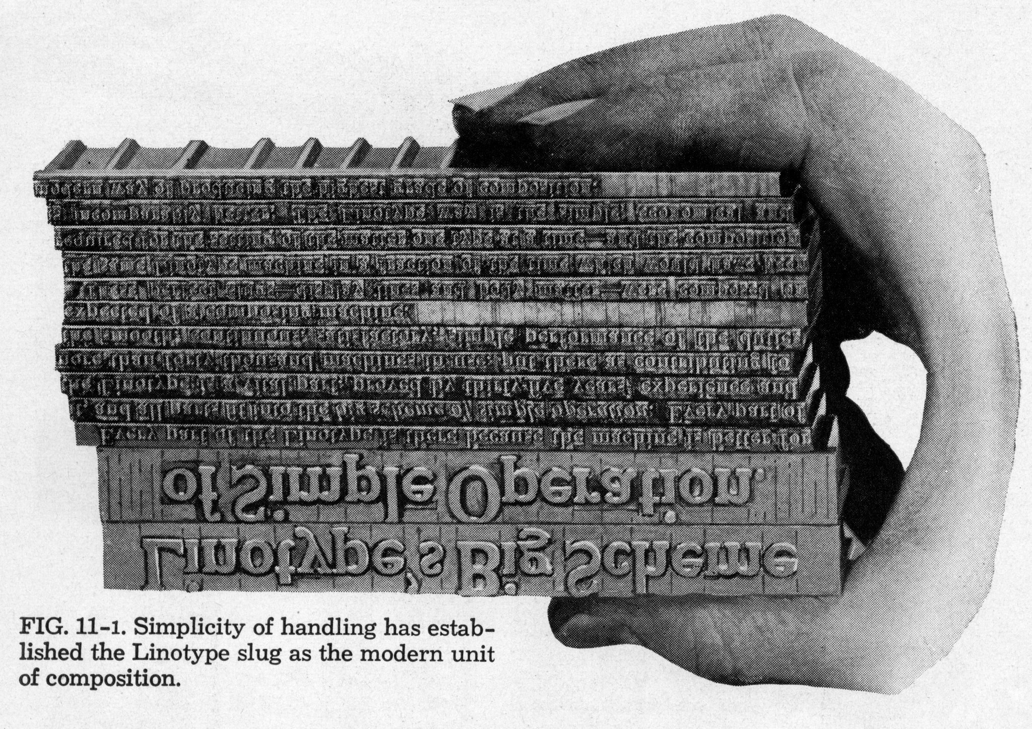
Here is a group of slugs forming a more complete text. (Of course, to print from them you wouldn't just hold them in your hand; you'd put them in a framework (called a "chase") and put that, in turn, into a printing press.)
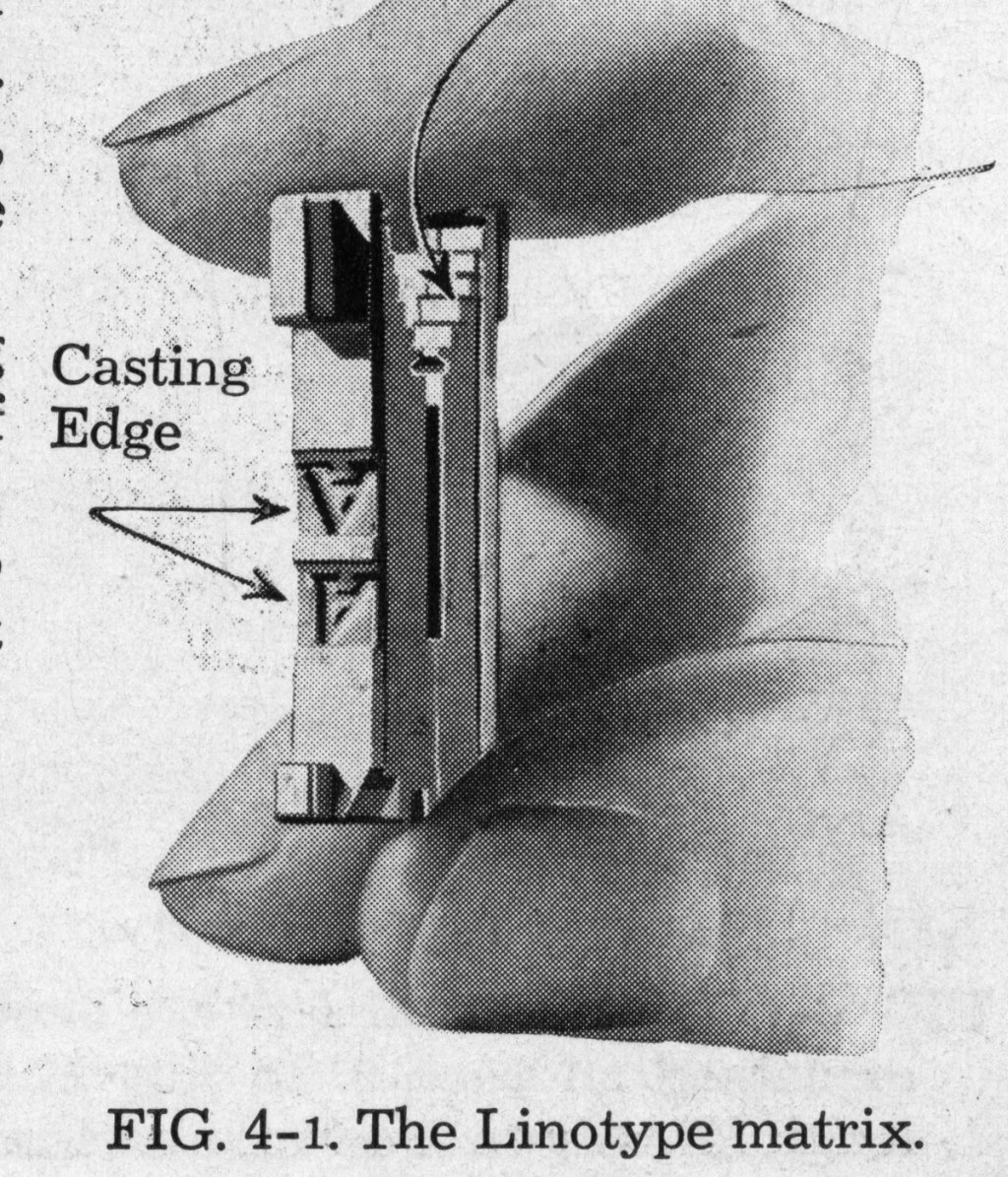
In order to cast this slug of type from molten typemetal, the Linotype uses a multi-part mold. The part of the mold that forms most of the body of the slug is fixed in the machine (I'm ignoring many subtleties of molds here, which aren't important to the Teletypesetter). The part of the mold that forms the "face" of the slug (where the letters are) is actually composed of many individual molds, one per letter, all lined up. An individual letter-mold is called a "matrix." (The plural of "matrix" is "matrices." Colloquially, they are called "mats.") Here is a matrix. Like most (but not all) Linotype matrices, it actually has two letter molds cast into it. Only one would be used for any given line (but either could be used, and the Teletypesetter had to be able to specify which one was used).
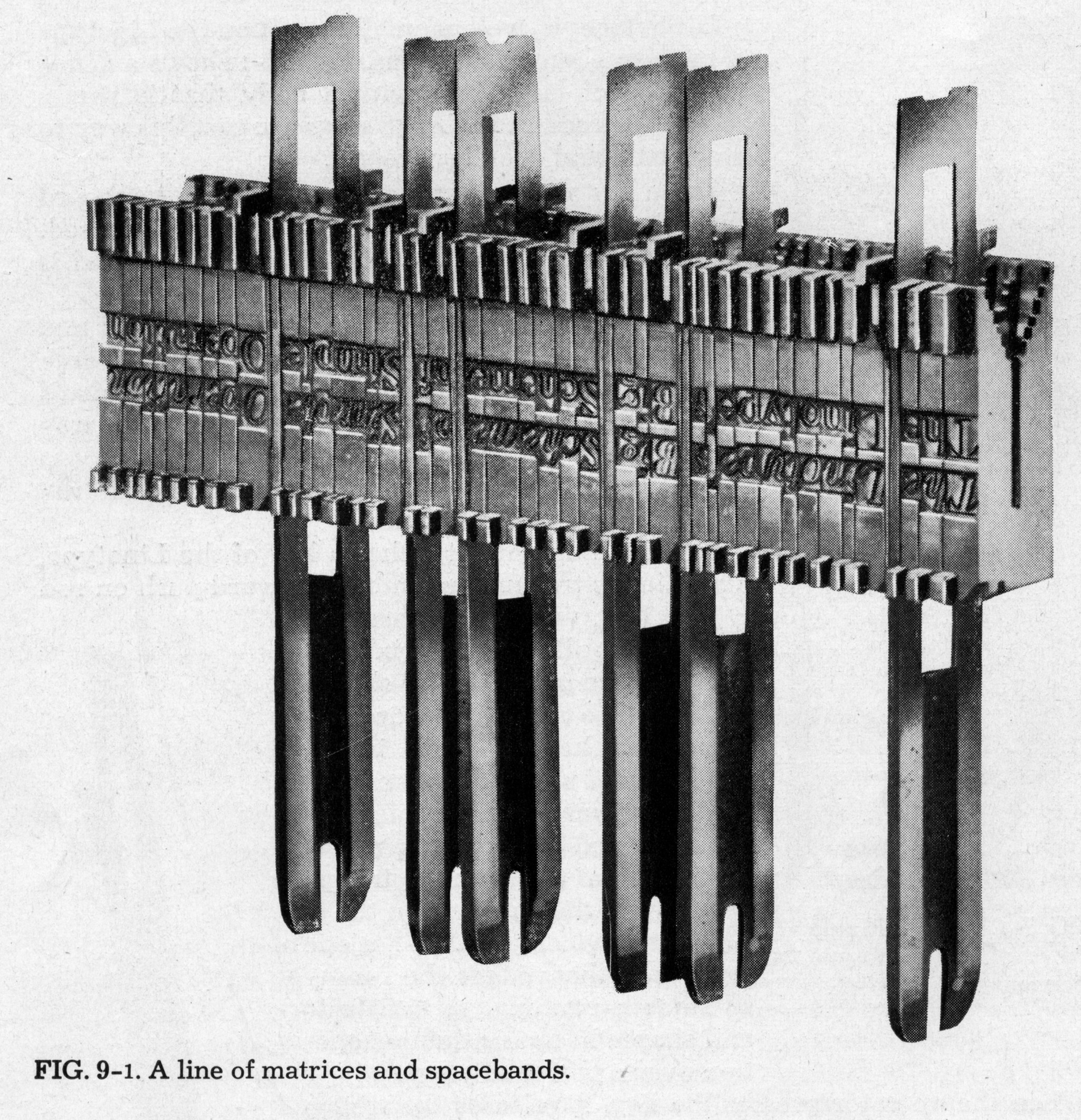
The illustration below shows an entire line of matrices assembled for casting. (Of course, it shows them just hanging in the air; in reality they would be held in the machine.) The mold lines up with only one or the other of the two lines of letterform-molds in this line of matrices. The slug which this line of matrices will cast would read "Linotype's Big Scheme of Simple Operation", either in Roman or Italic (depending upon which position has been selected).
The illustration also shows another important feature of the Linotype. The long thin elements between words are called "Spacebands." Each is a double-wedge which when pressed upon from below will widen. During the casting procedure, this is done so that the line is automatically justified. The space between each word is identical for any given line, but varies between lines (depending on how tightly the line is locked up and how many spacebands there are in it). Spacebands were available in different widths to accomodate work which might more commonly need narrower or wider spaces.
Under the control of an operator at a keyboard (or a tape control unit for a Teletypesetter-equipped machine), a Linotype circulates matrices through the machine. It (and the Operator or the TTS) assembles a line of matrices, moves them to a casting position, and casts a slug (line-o-type) using their letter-molds. While the slug is delivered to the user, the matrices are then automatically "distributed" back into their storage magazines. While a line is casting, an operator can be setting a new line. A good operator was said to "hang the machine" (a positive term) when he or she was simultaneously assembling one line while the previous line was in the process of casting while the line prior to that was in the process of distributing.
Here is a "phantom view" of a manually operated Linotype which I've annotated to trace this process. It is from The Big Scheme of Simple Operation .
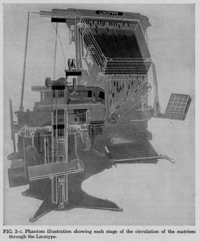
Start at (1). Matrices are stored while in use in one or more "magazines" mounted on the machine. Each magazine contains a single font of matrices. (Simplifying,) each magazine has 90 vertical channels, each of which holds up to 20 matrices of a particular character. Depending upon the machine, either one or two magazines may be in operation at any given time (if there are three or four magazines mounted on the machine, these must be moved into position manually for use).
Under the control of a keyboard (5), escapements at (2) release the matrices from the magazines. The matrices travel through the Assembler Front (3), which consists in part of free-fall and in part of an inclined belt. They are assembled in the Assembling Elevator (7). An operator (but not a Teletypesetter) can add or subtract matrices by hand at this point. Spacebands, as desired, are dropped straight down from the Spaceband box (4) into the line as it is assembled.
When the operator presses down on the handle (6), the Assembling Elevator rises to position (8). At this point, the operation of the rest of the machine enters an automatic cycle. The line of matrices is transferred through (9); at the same time, the Assembling Elevator (7) may be lowered and a new line begun.
The line of matrices continues its transfer and is moved into the jaws of the First Elevator at (10). The First Elevator then descends with the line of matrices to Casting Position (11). The cast occurs, and the resulting slug is delivered to on the Galley (12).
Once the casting has occurred, the First Elevator rises to position (13) and begins the Second Transfer of the matrices. The Second Elevator (16) desends to position (14). The line of matrices slides onto the Second Elevator, where the Combination Teeth of the matrices engage corresponding rails in the Second Elevator. At this point any matrices which have no Combination Teeth drop off and fall into the Quad Box (15). These are usually larger matrices, such as logotypes, which will not fit through the regular distribution mechanism. The Second Elevator rises (in this picture, it is shown at (16) rising with a line of matrices on it). The spacebands have no Combination Teeth (but are also designed not to fall into the Quad Tray). They remain at (14) when the Second Elevator rises, and are then gathered by an arm and returned to the Spaceband Box (4).
The Second Elevator rises to (17), and the line of matrices is pushed off it, through the Distributor Box (not identified here), and onto the Distributor Bar at (18). The pattern of rails on the Distributor Bar engages the Combination Teeth on the matrices in such a way that the matrices slide along it until exactly the point where they are over their proper channel in the Magazine. They then fall off the Distributor Bar and re-enter the Magazine to be re-used.
Any matrices which have all seven pairs of Combination Teeth present will not fall off of the Distributor Bar. Instead, they pass all the way through the Distributor and exit it on the right. They then fall down a chute (19) and are collected on the Pi Stacker (20). These matrices are typically special characters that are not accomodated by the magazine/keyboard layout. The operator keeps such matrices in a Sorts Tray shown just above (20) and inserts them manually into the Assembling Elevator (7). The Teletypesetter cannot, of course, do this.
As was seen earlier, the Murray and therefore the Morkrum/Teletype keyboard layout is deeply tied to the pattern "ETAINO SRHDLU". For different reasons stemming from similar cuases, the Linotype is deeply tied to the pattern "ETAOIN SHRDLU" (unless you're in France, where the pattern is ELAOIN SDRETU, as readers of the Belgian comic Le Petit Noël know well).
As the matrices in a Linotype descend through the Assembler Front ((3) in the annotated illustration above), they fall freely for some distance and then travel on a diagonal belt. There is some possibility that a fast operator might first release one matrix and then release another to its left before the first matrix had passed the location of the second. This would result in a transposition in the line. To minimize this, it is desirable that the most commonly used matrices do as much of their traveling as possible in free-fall and as little as possible on the belt (the belt, while fast, is slower than free-fall). This means that the layout of the matrices in the magazine starts out, left to right, with the most commonly used letters. Mergenthaler identified this pattern as lowercase "etaoinshrdlu...".
The Linotype keyboard, shown below, corresponds to this magazine layout. (In this section I'm using Linotype keyboard diagrams which reflect manual operation, not Teletypesetter operation. The principles will remain the same when moving to the TTS, but some of the keyboard details will no doubt change.)
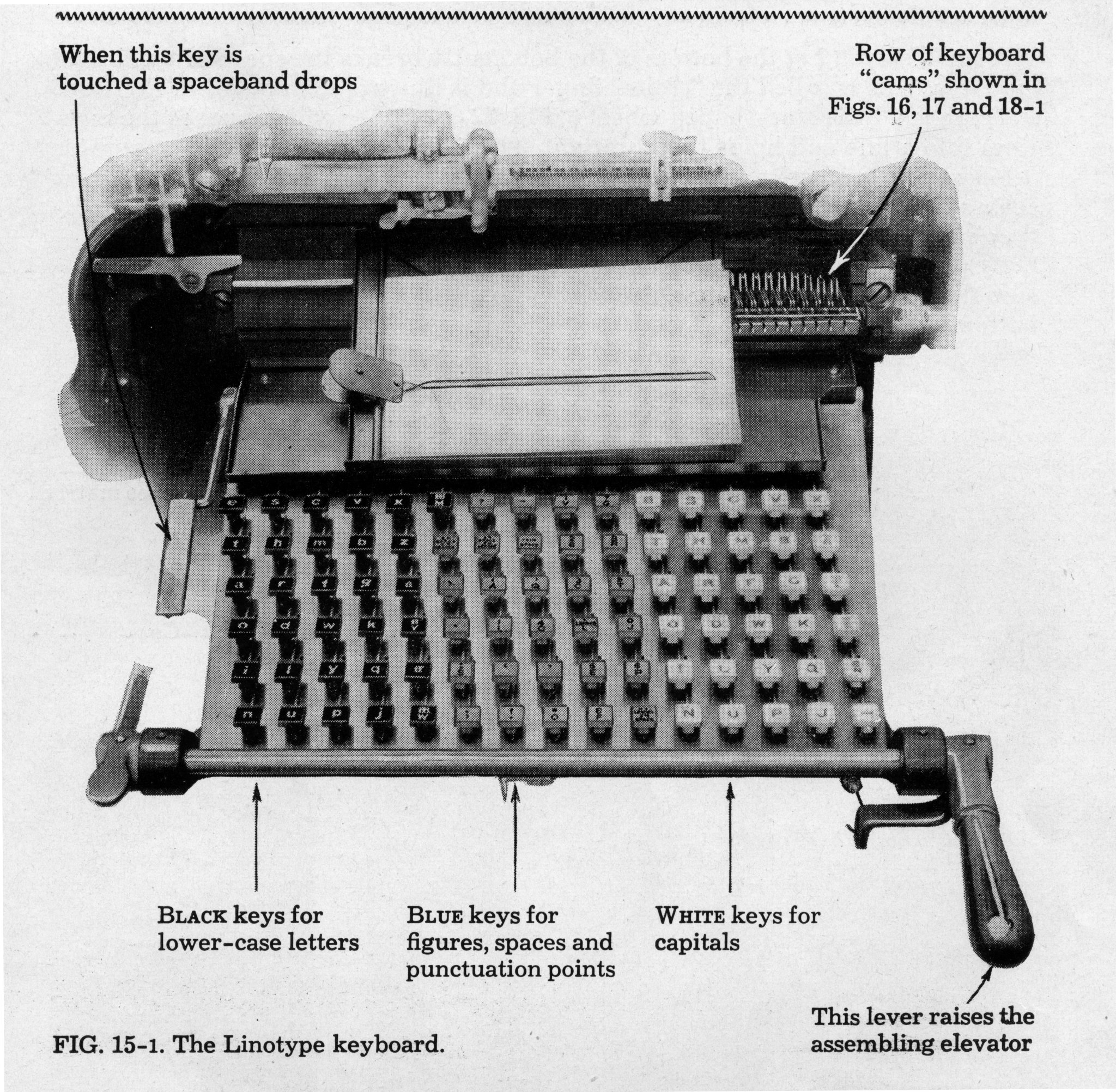
Here's a clearer diagram of a keyboard layout itself, for a standard 90-channel magazine arrangement.
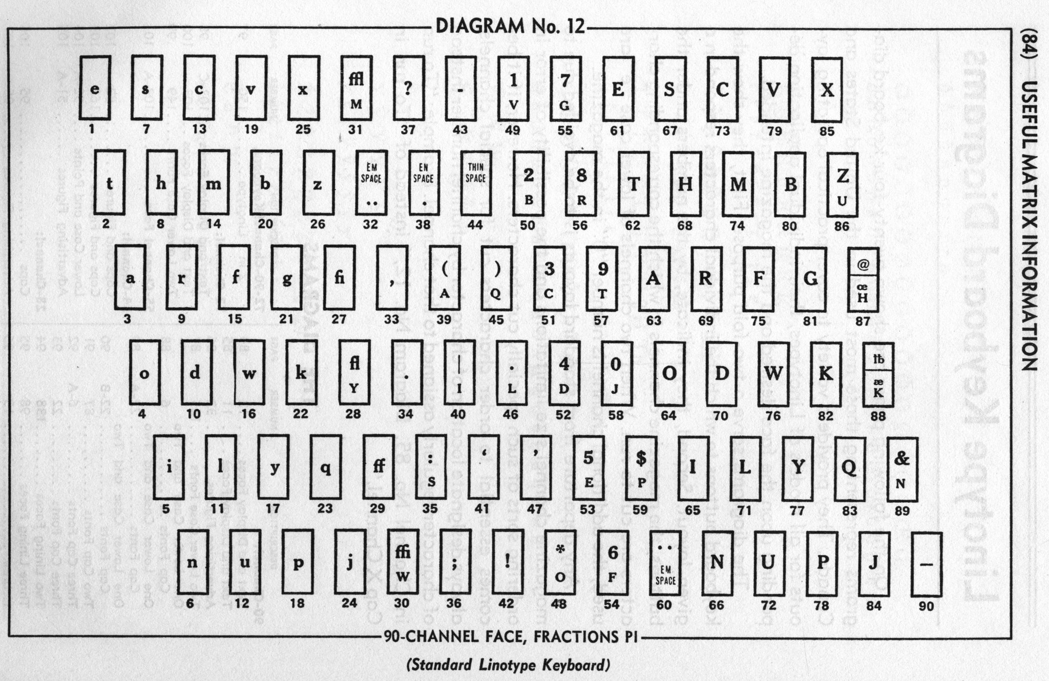
(From Useful Matrix Information : p. 84.)
The numbering of the keys ('e' = 1, 't' = 2, etc.) corresponds to the left-to-right arrangement of the channels of matrices in the magazine.
A study of this keyboard diagram reveals several points which will be significant for the Teletypesetter.
First, the Linotype (and any telegraph controlling it) must represent both lowercase and uppercase. The Linotype keyboard does not use a shift key like an ordinary typewriter, but instead duplicates the lowercase and uppercase keys. (The Teletypesetter, as it turns out, did use a shift to get to uppercase.) The left third of the keyboard contains the lowercase alphabet. The right third contains the uppercase alphabet. The middle contains a miscellany of characters; some of these will be relevant to the Teletypesetter, while some will not.
The left third, nearer to the middle, contains several characters which may be unfamiliar. These are the "ligatures": fi, fl, ff, ffi, and ffl. On a typewriter, these are typed as separate characters. However, in fine printing these letters must be set much closer to each other, often joining into a single glyph. Because of its use of a line of discrete matrices, the Linotype could not accomplish this using successive matrices. (There will always be a space, however slight, between an 'f' and an 'i' following it; good typography requires that they touch.) The Linotype solution was to provide these as separate matrices, in separate magazine channels, controlled by separate keys. The Teletypesetter had to accomodate this.
The middle third contains the digits, of course. It also contains some standard punctuation. In addition, it contains Spaces and Leaders. The Linotype achieves line justification by the use of spacebands, as described earlier. However, it is also useful to have fixed-width spaces of various sizes. The Linotype provides three: an "Em" space, and "En" space, and a thin space. To a printer, an "Em" space is a space the width of which is exactly equal to the height of the type. So for 12 point type, an Em space would be 12 points wide (even if the 'M' character happened to have a slightly differen width). An En space is half the width of an En space. A "thin" space is thinner, but its exact width is left to the type designer. A "Leader" is a row of dots (which, when set successively, lead the eye across the page). These were provided in Em-wide and En-wide versions (keys 32 and 38; if you're wondering why the "shifted" versions of these keys appear underneat the regular versions on the keycap, wait until the discussion of the upper and lower rails later). A thin space usually provided just another thin space in both positions (there isn't much room on a thin space for anything else). The standard keyboard also provided Em spaces and Em leaders in an opposite combination (key 60).
The middle third of they keyboard was also used in manual operation (but not TTS operation) to provide small caps. These appear in an essentially random layout dictated by space remaining after other things were accomodated.
The right third of the keyboard contains the uppercase letters in the same ETAOIN pattern, along with other punctuation and less usual characters (the 'oe' and 'ae' digraphs, and the 'lb' symbol). Note that the Linotype distinguishes between the hyphen (key 43) and the longer Em-dash (key 90); the Teletypesetter retains this distinction.
By "Fractions Pi" the diagram means that matrices containing characters as fractions (e.g., "1/2" as a single character) were not accomodated in the magazine or keyboard, but instead were inserted by hand by the operator. ("Pi," to a printer, means mixed-up or jumbled type or matrices.) It was also possible to arrange a magazine/keyboard such that these fractions ran in the magazines. Here is a keyboard layout for this:

(From Useful Matrix Information : p. 85.)
The fractions simply replace several of the lesser-used ligatures and punctuation characters. The Teletypesetter retained the possibility of running fractions.
There were innumerable other keyboard layouts for manual Linotype operation (especially for non-English typesetting both internationally and in non-English newspapers in the U.S.) An examination of Teletypesetter Corporation "Specification" documents from the 1930s indicates that to a great extent the Teletypesetter Corporation supported unusual arrangements on a per-customer basis. The two keyboard arrangements above, however, will suffice for the present.
[TO DO; although it is not relevant to the TTS code, Mergenthaler rediscovered binary counting as a basis for mechanical sorting. For a study of this, see: Decoding Matrices 2: Teeth, Channels & Characters/Fonts in The CircuitousRoot Typefoundry and Press . ]
Take another look at the Linotype matrix as shown earlier. It has not one but two letterform molds on it. (Some matrices for very large type had only one mold, but we can ignore that here.) Generally, the two positions on the matrices in a font of matrices were coordinated typographically. One might contain the Roman version of the typeface, while the other might contain the Italic.
The Assembling Elevator in a Linotype has two sets of "rails" on which a matrix rests: a regular or lower set of rails, and an optional upper set of rails. If the upper rails are engaged, the operator can select whether a matrix will sit on the lower rails or the upper.
Because of the way in which a Linotype matrix is oriented in the machine, this means that of the two letterform molds on the matrix the regular one is the upper (used when the matrix sits on the lower rail) while the alternative one is the lower (used when the matrix is raised up onto the upper rail). (This, by the way, is why a Linotype keyboard will show alternative symbols for a key below the regular ones. This seems backwards only if you're trained on a typewriter with a shift key. The Linotype has no shift key, and the positioning of the symbols on the keycaps corresponds to their positions on the matrices.)
Here is a view of the Assembling Elevator, shown mysteriously detached from the Linotype itself. As shown, the matrices on the left (spelling "Linotyp") are on the upper rail and so their lower casting position lines up for use. The three matrices to the right are on the lower rail, and so their upper casting position will line up for use. The Upper Rail itself is called out as "1". The short extension of it being manipulated by the operator is used to select whether incoming matrices assemble on the upper rail or (in the state shown here) the lower rail. By moving the lever to the left, the upper rail can be disengaged entirely.
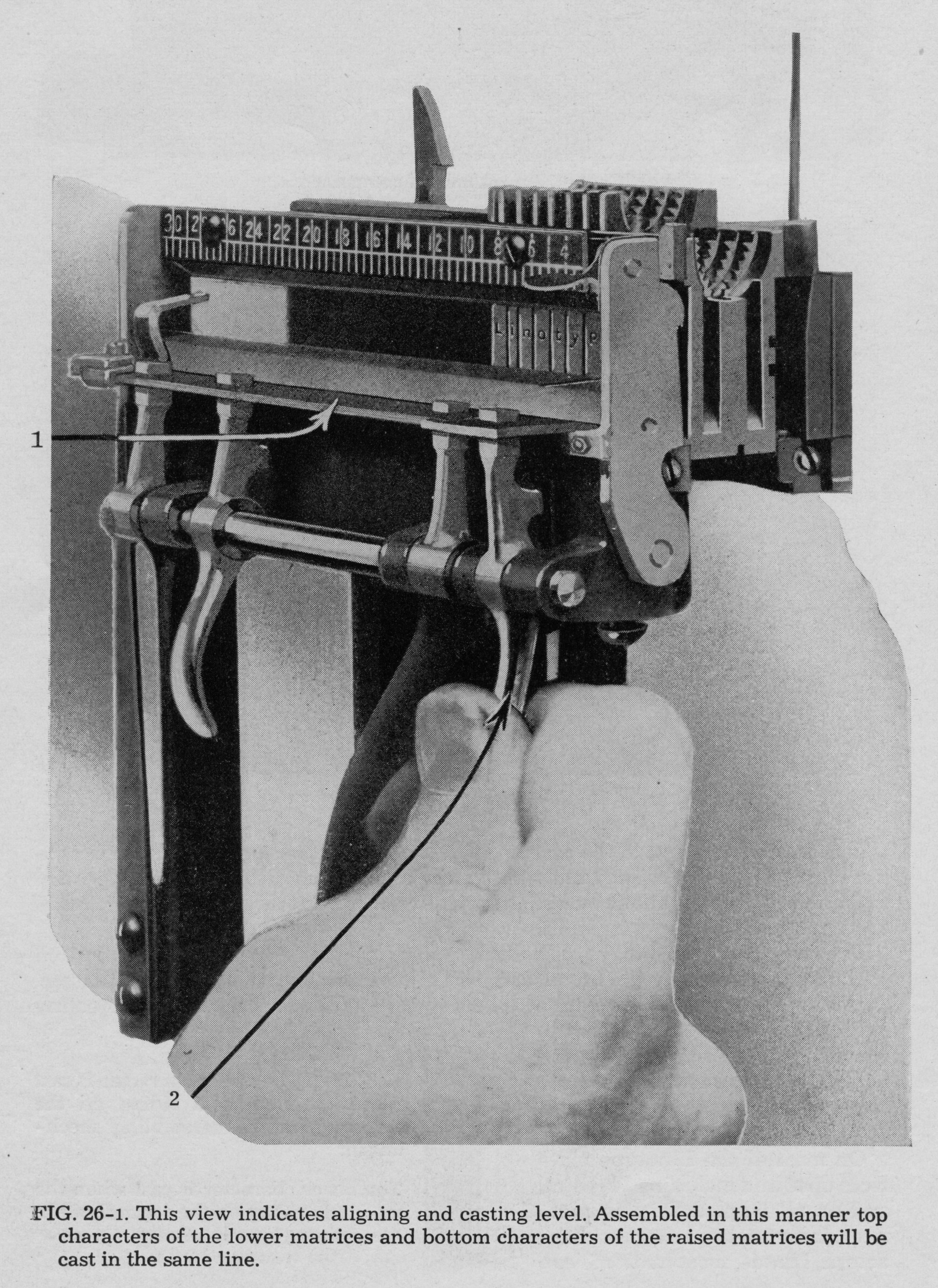
The Teletypesetter, therefore, must be able to signal to the Linotype that a matrix should be assembled on the lower rail or the upper rail. In practice, the TTS code does this with a shift: "Upper Rail" to cause matrices to start being assembled on the upper rail, and "Lower Rail" to cause them to start being assembled on the lower rail.
"Quadding" is the last major function of the Linotype that the Teletypesetter must accomodate. It is a simple concept, although it can be perplexing to those without printing experience. I'm not sure that a picture of a quadder will help here, although seeing one in operation makes its use clear immediately.
In traditional hand-set typography, a "quad" ("quadrat" to the English) is another word for an Em Space. It's a square space. If a line is to be set flush left (for example), quads and other spaces must be added to the line to fill it out to the right. This process is termed "quadding."
An analogous method is used on a Linotype when the machine is not equipped with an automatic "quadder" (and the quadder was always an optional device, even though it became a very common one). The operator would "quad out" the line manually using Em Spaces and En Spaces (not spacebands, for reasons that aren't relevant here).
This process was of course tedious. A quadder automated it. A quadder manipulates the jaws of the vise in which a line is held for casting so that the jaws themselves move and automatically fill out the line. Moreover, the quadder was also built so that it could, optionally, "quad right" (set flush right) or center a line (quad equally from both left and right). It could also be disabled for regular full-justified lines. Lines which are quadded are set entirely with fixed-size spaces, not spacebands (mechanically, you don't want the spacebands trying to expand the line while the quadder is trying to compress it).
The Teletypesetter accomodates all three kinds of quadding: "Quad Left," "Quad Center," and "Quad Right."
Toward the end of the Teletypesetter era, the capabilities of the system were expanded to include control of other features of the linecaster previously controlled manually. Some Linotype "Elektron" models, for example, could change magazines under TTS control. The Mohr Lino-Saw company also figured out how to use the TTS to control their linecaster-attached slug saw. None of these later, advanced features are relevant to the present discussion, however.
The other aspects of linecaster tape control that are easy for "software" people to overlook have to do with keeping the machine running. The Linotype and Intertype, while remarkably reliable machines, were also remarkably complex machines designed to be run by a skilled operator. In addition to typing, the operator cleared jammed matrices from the machine, and generally kept it in order. The fact that the machines were run harder (faster) in TTS operation didn't help here.
A linecaster under TTS control, therefore, had to be in much better operating condition than normal. Linotype published special maintenance instructions for this. Additionally, the machines were often "instrumented" with additional apparatus to detect mats gone awry (Teletypesetter had their own unit for this, but the most successful mat detector was the Shaffstall.)
These considerations are all important in understanding the Teletypesetter (and why the tape control of linecasters took decades to accomplish). They are not, however, relevant to understanding the code.
The Teletypesetter system may be a bit unfamiliar both to Teletype and to Linotype enthusiasts, so perhaps a bit of potted history is in order.
The idea of controlling a Linotype by telegraph or tape is not new. The initial interest of Frank Pearne in printing telegraphy (which led, through his collaboration with Charles Krum and Joy Morton, to the Teletype) included Linotype control. [ Note 9-1]. Independently, Donald Murray was interested in Linotype control as well. His paper "Setting Type by Telegraph." (1905) actually only considers this very briefly (p. 593 / PDF 638). Interestingly, Murray indicates that "three years" previously the Mergenthaler Linotype Company had experimented with using Murray apparatus. Murray's conclusion, however, is that:
"All that can be said about automatic typesetting by telegraph is that it is a possibility of the future, and that if it is done it will have to be done on the lines of the Murray apparatus, because the Murray system alone is practical both from the newspaper and from the telegraphic point of view." (p. 593 / PDF 638)
Insofar as the Teletype code is Murray's code, and the Teletypesetter was in most respects a Teletype derivative, Murray was quite correct.
(Proponents of the Monotype, a competing system of "hot metal" type composition, will of course note that the Monotype was controlled by tape from its initial design. However, the Linotype dominated the newspaper industry, both because of its greater speed and because it produced easy-to-handle slugs of type (the Monotype cast individual types). The greatest field of application of telegraph control to type composition was the newspaper industry, so it was the Teletypesetter controlling Linotype (and Intertype) linecasters which dominated the telegraph control of hot metal composing machinery.)
The Teletypesetter itself began in the 1920s with an interest by the Rochester (NY) newspaper publisher Frank E. Gannett in such a system. He investigated this with the engineer Walter W. Morey, but they discovered that Teletype (then Morkrum-Kleinschmidt) held blocking patents. They therefore went to Morkrum-Kleinschmidt to develop the system. Its development there was undertaken by E. Kleinschmidt (as vice president of Morkrum-Kleinschmidt, but also an enginer of note) and Dr. L. M. Potts (as research engineer). Snyder cites an initial public demonstration on Dec. 6, 1928, at the Rochester Times-Union. [ Note 9-2] The US Patent and Trademark Office record for the (now lapsed) trademarks (in two categories) "Teletypesetter" gives a date of first use of 1928-11-15.
Although the Teletypesetter was available from the early 1930s, it took a while for it to become widely accepted. The Associated Press did not adopt it until 1951, and it was not until 1962 that AP linked all of their TTS circuits into a single network. [ Note 9-3] and [ Note 9-4] By the end of "hot metal" composition in the newspaper industry in the 1970s, however, the TTS was in widespread use. The Teletypesetter Corporation itself was spun off to Fairchild in 1958 [ Note 9-5]
By that time competing systms had been developed as well (especially the Mergenthaler Linotype Company's Linomatic Tape System (LTS) [ Note 9-6] and the Star Parts Company Star Autoperf and Star Autosetter systems [ Note 9-7] and some auxiliary third-party equipment had been introduced (especially the Shaffstall Mat Detector [ Note 9-8]). In addition, standalone tape and computational equipment was developed (for example, the Compugraphic "Justape," which could read a "straight" (non-TTS) news story from tape, justify it for the linecaster, and then reperforate it to a new tape [ Note 9-9]). In the end, TTS equipment merged into tape-controlled phototypesetting composing machinery (Mergenthaler Linotype's Linoquick Perforator, for example, could feed both a conventional hot metal Linotype and the "Linofilm Quick 'phototextsetter'" [ Note 9-10]).
The reasons for the success of the Teletypesetter have, however, worked against its preservation. It was used primarily by large newspapers. These were the first to scrap it when new technologies came around. The few surviving Linotype shops tended to be smaller shops which never had TTS. Moreover, the TTS seemed to split into two communities. To a Linotype operator, the TTS was just another way to control a Linotype (and not necessarily the fun way; old Linotype operators sometimes speak of TTS-equipped Linotypes as "robots.") On the other side of things, a Teletype(setter) operator might never see a linecaster. The remaining Model 20 Teletype printers (capable of 6-Level TTS operation) are now simply seen as upper-and-lower-case Teletypes.
There was, however, quite a lot to the system. One good overview of the mature system is Fairchild's More Type In Less Time through Automatic Typecasting . Here (drawing in part from that document) is a very brief survey in images of the Teletypesetter:
In most installations, the linecaster was controlled by a "Teletypesetter Operating Unit" (TOU) attached to the linecaster keyboard. A machine so equipped could be run either manually or under tape control. In the image below, the TOU is visible to the right of (and underneath) the keyboard.
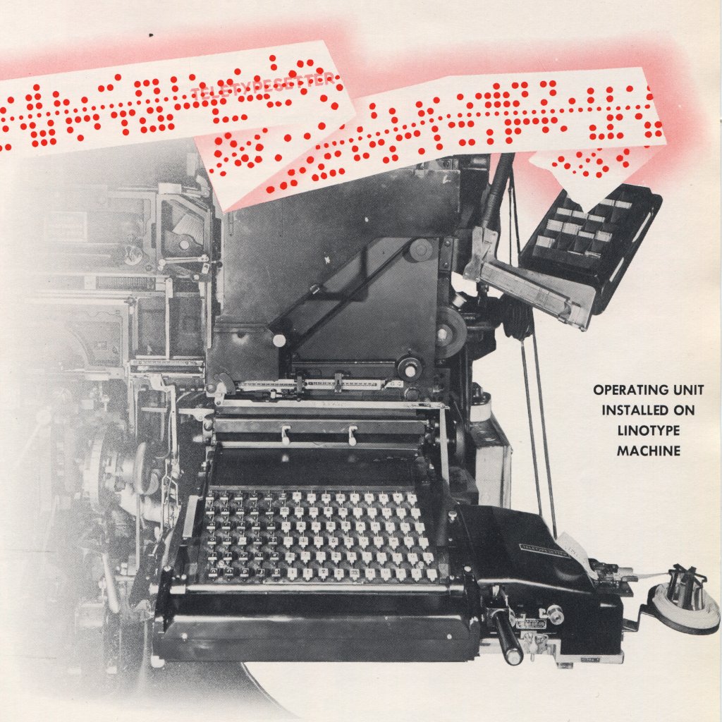
(From More Type In Less Time through Automatic Typecasting .)
Later, things became sleeker and more integrated. Here is a Linotype "Elektron" from around 1962. It is equipped with the Teletypesetter-compatible Linomatic Tape System. A few later machines even eliminated the keyboard entirely. For all its automation, however, it still has a pi stacker, and you could, if you wanted, still put mats in by hand.
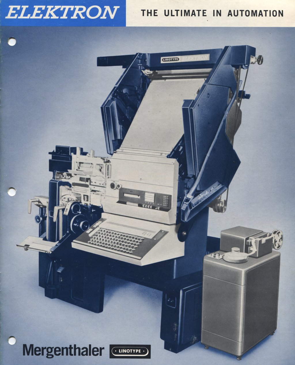
(From Elektron: The Ultimate in Automation .)
The tape was punched on a keyboard perforator. This had a QWERTY (not ETAOIN) keyboard, with extra keys for TTS-specific functions. The pointers and scales indicated the line length for which the linecaster was set, the length of the line already typed, and the room for the spread of the spacebands. Just as in the direct use of the Linotype, there was considerable operator skill involved in deciding how long a line should be and where lines should be broken. (Old Linotype operators generally cringe when reading modern newspapers. In a linecaster-set newspaper, a human brain was involved in typesetting every line. The computer algorithms just aren't that good yet.) Considerable operator skill was also involved in seeing what had been punched. The operator had to read the punches on the tape directly to do this. To the best of my knowledge, no Teletypesetter Perforator ever printed (either to tape or to page).
The tape take-up reel to the left of the punch was available in both clockwork-drive and electrical-drive models.
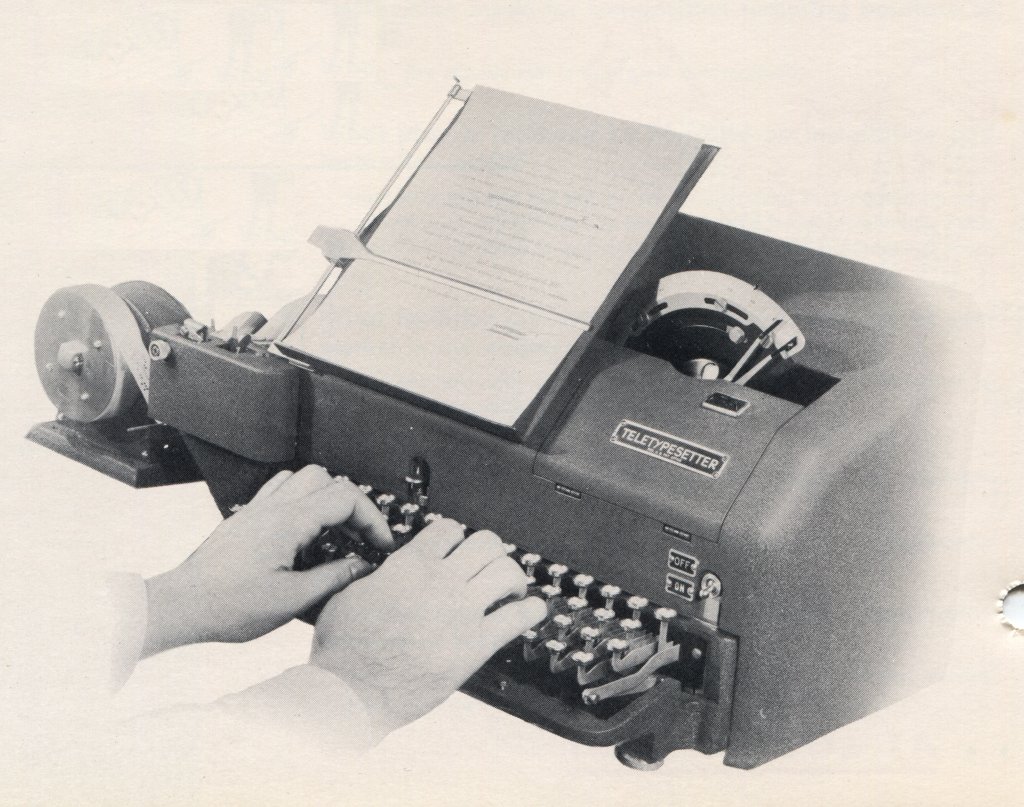
(From More Type In Less Time through Automatic Typecasting .)
The unit shown above is a "Standard Perforator." Linecaster matrices are of various widths (vs. fixed-pitch typewriters or Teletype printers) A Standard Perforator was used when the linecaster was set up for "unit fonts" of matrices. These were designed to a particular set of widths. A "Multiface Perforator" (shown below) used a "counting magazine" which told the Perforator how wide the mats of the desired font were. (All TTS operation involved the use of specific fonts of mats for which there was TTS support - either a unit font or one for which there was a Multiface magazine. You couldn't run just any old font of mats and expect it to work.)

(From More Type In Less Time through Automatic Typecasting .)
Here's a closer look at the "Indicator Scale" by which the Perforator operator judged the spacing and division of lines.

(From More Type In Less Time through Automatic Typecasting .)
The Teletypesetter Perforator Operator's Training Reference Manual (1953) uses this same illustration and explains it thus (pp. 41-43):
"On the Teletypesetter Perforator, line justification is achieved by means of the Counting Scale with it three pointers - the Counting Pointer, the Left-Hand Spaceband Justification Pointer, and the Right-Hand Spaceband Justification Pointer...
[I would insert here that the length of the line as set up in the linecaster mold is read on the Counting Scale, from right to left. The Counting Scale itself is adjusted to set this length on the Perforator.]
"The counting pointer moves along the counting scale from left to right as the keys are depressed for the various characters. The distance that the counting pointer moves for each keystroke depends on the matrix width of the character selected. ... Thus, as the counting pointer moves along the counting scale, it registers the cumulative widths of the characters used in the line.
"When the space[band] bar is depressed, the counting pointer remains stationary - but the counting scale itself ... moves from right to left. This movement of the scale measures the thin part of the sapceband (the minimum width of the sapce). At the same time, the left-hand spaceband justification pointer moves to the left a distance corresponding to the thick part of the spaceband (maximum space width)...
"When the counting pointer moves into a position between the two spaceband justification pointers, the line is considered to be within the 'justification range' and may be ended by depressing the return (RET) an then the elevate (ELEV) keys.
"The spread ... between the two spaceband justification pointers represents the allowable range for ending the line...
"If the line is ended before the counting pointer has passed the left-hand spaceband justification pointer, the result will be a loose line which will not cast a 'slug' on the linecasting machine. If the counting pointer is beyond the right-hand spaceband justification pointer, a tight line will result. ... Either condition may cause damage to the equipment."
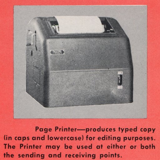
(From More Type In Less Time through Automatic Typecasting .)
In addition to this linecaster-specific equipment, there was also the "Teletype side of the house." The Teletype Model 20 page printer is a 6-Level machine adapted from the standard 5-Level Model 15. This was Teletype-branded equipment.
For a KSR (Keyboard Send-Receive) version of the Teletype Model 20, see Teletype Bulletin 161, Description: TypeBar Page Printer Model 20 . .
There was also a 6-Level Transmitter-Distributor for Teletypesetter use. The unit shown below looks a lot like a standard 5-Level Model 14 TD; I do not know its Teletype model number, however.
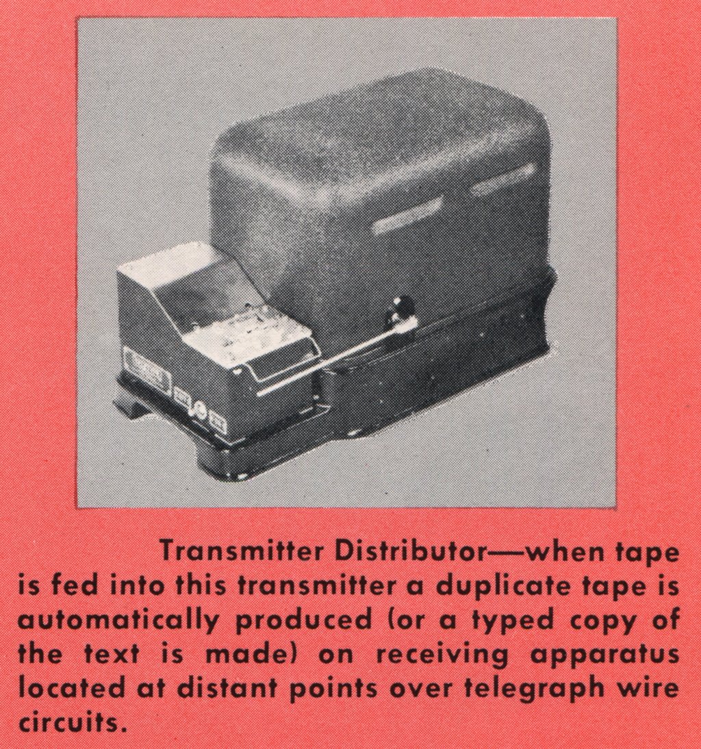
(From More Type In Less Time through Automatic Typecasting .)
The opposite of a Transmitter-Distributor is a Reperforator. There was a 6-Level TTS Reperforator as well. I do not know the Teletype model number for this unit.
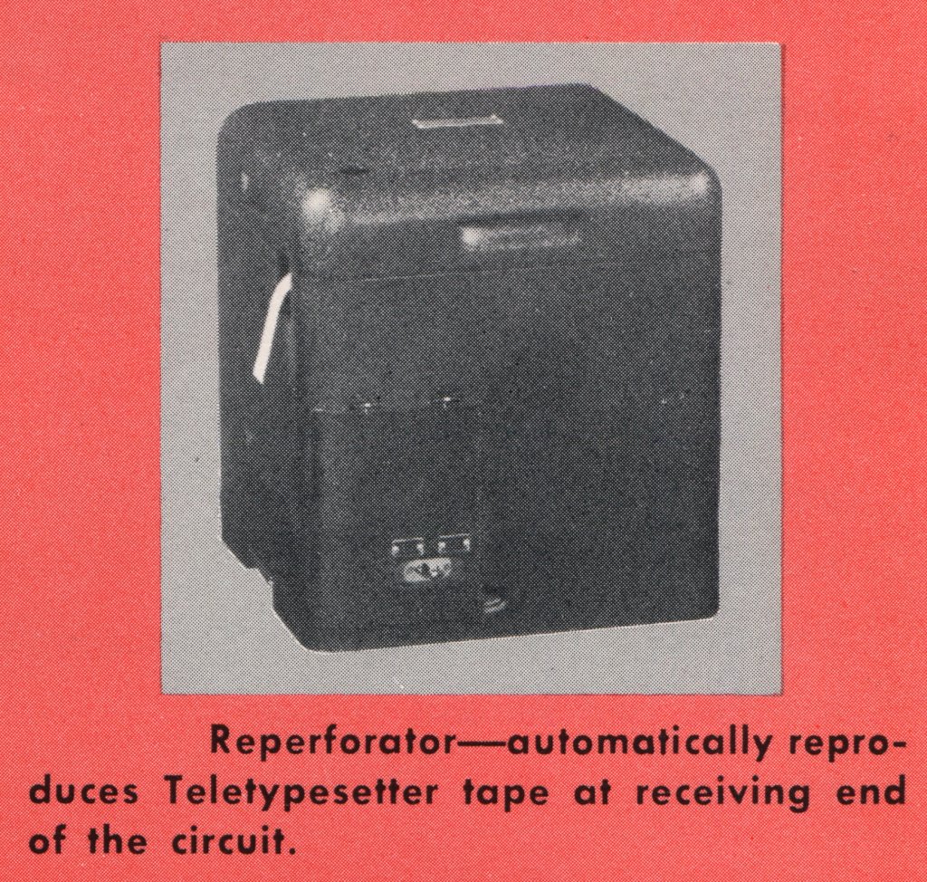
(From More Type In Less Time through Automatic Typecasting .)
While you could carry a tape by hand from a Perforator or Reperforator to a linecaster's TTS Operating Unit, you could also link a Reperforator up to a TOU pretty directly:
(From [Fairchild/TTS] New High-Speed Transmission Equipment . The TOU in the image above is Fairchild-branded, but the TD is Teletype-branded.)
Especially later, after the TTS became widely accepted, more specialized equipment became available. The image below is of a Fairchild TTS Selective Allotter:

(From Fairchild TTS Selective Allotter .)
By way of explanation: There were two basic points to the Teletypesetter: (1) to provide for remote use of a linecaster via a telegraph circuit, and (2) to maximize the throughput on the linecaster. As far as this second point was concerned, there were two basic bottlenecks: Linotypes can cast faster than even the best Linotype operator can type, and changing a Linotype from one kind of work to another is slow (it involvs changing heavy magazines of fonts, possibly changing molds, and so forth). With TTS, multiple TTS Perforator operators could generate tape fast enough to keep a linecaster occupied. If, in addition, you could dedicate a linecaster to a special type of work (general news copy, the classified section, etc.) then you could avoid the downtime of changing the machine setups. (A large newspaper might have dozens of linecasters.)
The TTS Selective Allotter acted as a switch to facilitate this. Work was divided into up to three "groups" (types of work), and up to 10 linecasters were configured so as to be in one of these three groups. The Selective Allotter had up to 15 input channels, each of which could be either a wire service feed or a local Perforator/Transmitter-Distributor combination. The input channel could specify what group its input was part of (and this could change from one chunk of input data to the next; a single Perforater operator could punch general news stories for a while and then switch to the classifieds by operating a simple switch). The allotter then took all of this input as it was presented and routed (allotted) it among the output linecasters in such a way as to keep each linecaster in each group as busy as possible.
I have no idea whether Fairchild sold many of these or not, and how many of them might survive. No small shop would have needed one, and no large shops stayed with hot metal.
This isn't the place for a comprehensive list of third-party TTS-related equipment, but I'll show one more item just to give a sense of the range involved. This is the Compugraphic Corp. "Justape" (shown here in the Mergenthaler Linotype Corp. rebranding as the "Linasec Justape"). This was a standalone computer. It read in a 6-level tape containing TTS data entered without regard for line length or justification (so that the Perforator operator didn't have to think, but could just type). It computed the end-of-line and justification decisions for this data and punched out a TTS-ready tape for use in either a linecaster or in a Linofilm Quick phototypesetter. The output punch was a standalone Teletype BRPE High-Speed punch.

The previous two technical histories of the Linotype and the Teletypesetter are simply by way of introduction to the Teletypesetter code itself. Unless you understand the Linotype and its requirements, and the way in which the Teletypesetter constituted a complete system of telegraphically controlled automation, the TTS code isn't comprehensible.
For all that, the TTS code turns out to be quite easy to understand - if only you look at it with the proper historical context. Traditionally, this was not done. This is the way the TTS code is usually presented:

This is from a little plastic pocket rule that was probably given out as a promotional item by Fairchild. This presentation (given a document code of "TS 729" is basically the same as the others I've seen (one coded "538 TS" in Teletypesetter Perforator Operator's Training Reference Manual. or a larger fold-out Fairchild chart coded "668 TS")
The problem with it is that the layout of the code on it is designed to be easy to learn (at least someone at Teletypesetter and/or Fairchild thought it would be easy to learn with this layout). It is set up in regular, but not-quite-repeating patterns. They aren't binary. Moreover, the order of the columns along the tape is backward with respect to traditional Teletype use (counting 5,4,3,2,1,0 left-to-right, where the standard TTY presentation is 1,2,3,4,5).
In Teletype Bulletin 161, Description: TypeBar Page Printer Model 20 , it is presented alphabetically, but with an even more curious column ordering: 1,2,3,4,5,0.
What one needs to do in order to make sense of this is to lay the code out according to its underlying principles. As it turns out, TTS code is a direct development of TTY code, which in turn is based upon Murray's code. The proper order for it is, therefore, "ETAINO...":
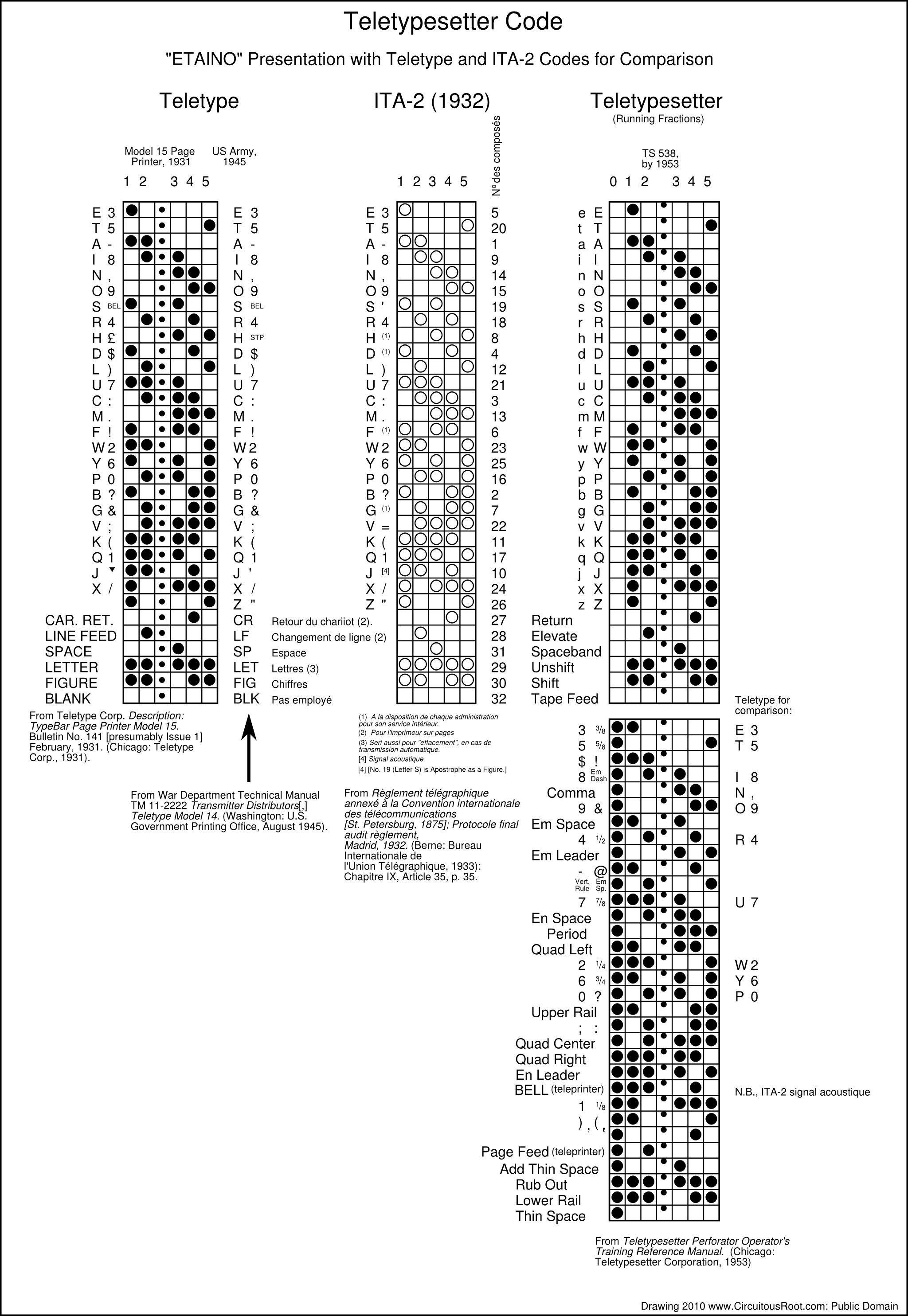
Here is a link to the SVG original of this drawing: tts-etaino.svg
The basic observation here is that the 6-Level Teletypesetter code is clearly based on the 5-Level Teletype code, which in turn is based on Murray's 5-Unit code. The reason for the layout of Murray's code was the minimization of wear on tape punches by following a regular pattern designed to use fewer punches for the most commonly used letters. The placement of the numbers in Murray's arrangement followed from the layout of the QWERTY keyboard. The output (punch) and input (keyboard) technologies led to the code layout.
In looking at the TTS code in greater detail, several lesser observations may be in order.
First, the TTS code is almost, but not quite, backward compatible with the TTY code. If you strip off channel 0, you do get the letters of the 5-Level TTY code, and reasonable equivalents for the "Return," "Elevate," etc. control codes. However, because the TTS code puts lowercase letters in those positions and uses a shift/unshift to get to uppercase, the semantics of the letters are not quite the same. More importantly, the shifted versions of the letters differ. If you strip off channel '0', a TTS shifted 'e' becomes not TTS 'E' but TTY '3'.
Second, the "upper half" of the code (positions 31-64) repeats the Murray pattern. This is seen because if this pattern is used then all but one of the TTS numbers fall in exactly the same locations that they would in Murray's pattern. (The exception is '1', which isn't quite in the right place.)
This allocation of the numbers in TTS is further interesting because the Linotype is not QWERTY, it's ETAOIN. The Teletypesetter Perforator, however, is QWERTY.
There is, however, one oddity in the TTS layout when compared with the TTY layout. The position of BELL in TTS isn't quite where one would expect if the upper half of TTS replicated TTY as far as possible. Instead, BELL is exactly where ITA-2 has "Audible Signal." I'm not sure what to make of this.
[TO DO] The basic point will be that ASCII, too, reflected its technologies. It is not based on any of the previous codes discussed (Baudôt's, ITA-1, Murray, Teletype, ITA-2, TTS). Instead, it is based on binary counting. If you take an ASCII 'A' (0x41) and add 5 to it, you get 0x46, which is in fact ASCII 'F' - the letter five up from 'A'. If you try to treat TTY 'A' as if it were a binary number (0b11000, or 0x18) and add 5 to it you get 0x0D = 0b11101, which is TTY 'Q'.
None of the earlier codes discussed were binary because they were not designed for computation. They were designed to encode given certain input and output equipment. By the time ASCII came around, though, there were computers upon and it made sense to treat character codes as binary numbers.
So this has been a great deal of verbiage on tiny little details of codes nobody uses any more and machines which in some cases no longer exist. Here's a sort of minimal summary (still with too many words):
Baudôt's code is a 5-unit code with units which, when transmitted over a telegraph line, are intended to be of equal duration. Baudôt seems to have introduced these principles, which therefore deserve to be associated with his name. The transmission system used was synchronous, not start-stop. The combinations of his code are not binary numbers. Its layout was designed to be easy to learn given a particular keyboard, the key-ordering of which differed from the transmission-ordering of the code. It was not initially intended to be punched to tape at all, although a tape was devised for it. The system was a printing telegraph which printed along a (non-punched) tape; it was not a page teleprinter.
In summary, the Baudôt code layout was determined by the need to teach the Baudôt 5-key keyboard to human telegraph operators.
As an aside, while Baudôt's code is not binary numbering, he effectively invented a binary shift register for decoding and printing it.
Baudôt's code was formalized into ITA-1 in 1932. ITA-1 was deleted in 1973.
Murray's code was also 5-unit and employed units of equal duration. It was designed to be used with synchronous transmission equipment, not start-stop equipment. It punched to a tape (although the punching was linear along the tape). It was also intended to drive page teleprinters. The alphabetic layout of Murray's code was designed to minimize the number of punches used for common letters (in an order beginning "ETAINO..."), thus minimizing the wear on the (single) punch. The numeric layout of Murray's code was determined by the existing layout of the QWERTY keyboard once the letters had been assigned code values. The code combinations of Murray's code are not binary numbers. Murray's code layout has nothing at all to do with Baudôt's, and properly should not be called "Baudôt," even though Murray himself begain the confusing practice of doing this.
In summary, Murray's code was determined by letter frequency and punch mechanics.
The Teletype code is based directly on Murray's. It is punched to tape, in a pattern going across the tape. It may be useful therefore to call this "5-Level" (the conventional usage) to distinguish it from Murray's 5-unit code punched lenghtwise on the tape. The Teletype code may or may not have been used first with synchronous equipment, but certainly achieved prominance used with the Krum start-stop equipment. It was used both for page teleprinting and for printing linearly on tape (though this latter use seems to have been primarily to assist in reading the tape).
Even though Murray called his code "Baudôt," and even though the Teletype Corp. called their Murray-derived code "Baudot" upon occasion, the Teletype code layout has nothing at all to do with the layout of Baudôt. The only similarity is that both are 5-unit codes with equal-length units when transmitted.
The Teletype code was given an international formalization in 1932 as ITA-2, and continues today as ITU-T Recommendation S.1. The Teletype code is almost, but not quite, a proper administrative variation of ITA-2.
The layout of TTY/ITA-2, like the Murray code upon which they are based, is determined by (English) letter frequency and the mechanics of Murray's (not Teletype's) punches (and by the QWERTY keyboard). The code combinations are not binary numbers.
The Teletypesetter code is a direct extension of the Teletype code. It is only partially backward-compatible.
Unlike all of the codes previously considered, the code combinations of ASCII are, in fact, binary numbers. It is possible to do limited binary arithmetic on them and come up with meaningful results.
Whereas the previous codes were determined by user considerations (an unusual keyboard for Baudôt), input device considerations (the QWERTY keyboard for Murray/TTY numerics), or output device considerations (the punch for Murray/TTY), ASCII was determined by the existance of and the ability to use computing machinery on character encodings.
The codes of Baudôt and Murray, and their derivatives with Krum, Morey, and others counted for a great deal from the late 19th to the late 20th centuries; most of the world's telecommunications and much of its newspaper printing used them. Even so, while you can count on them, you can't count with them.
The Associated Press. The AP Style Book for Teletypesetter Circuits. NY: The Associated Press, 1951.
This is available online on Dave and Beth Seat's Hot Metal Services website, www.hotmetalservices.com (in the Downloadable Documents section).
bsittler. [no title; "baudot.txt]. http://xent.com/~bsittler/baudot.txt.
This brief note argues that if you separate out the vowels and consonants into two separate sequences that Baudôt's code is a Gray code.
Beauchamp, Ken. History of Telegraphy. London: INstitution of Electrical Engineers
The bulk of Beauchamp's book is concerned with manual telegraphy. Machine-based telegraphy (Baudôt, Murray, Teletype, etc.) receives treatment only in an Epilogue. It should certainly not be judged on the basis of this epilogue, but nevertheless there are errors in it which should be noted.
On p. 397 he ascribes the invention and the naming of the Teletype to AT&T in 1924. This is not true; the Teletype was developed by the Morkrum company prior to 1924, and named by them. AT&T merely purchased their successor company well after 1924.
On p. 395, he presents a chart of the French and English versions of the Baudôt code. He attributes this chart to "Fleming. 'Principles of Electric Wave Telegraphy,' 1909." However, the first edition of The Principles of Electric Wave Telegraphy and Telephony (London: Longmans, Green, and Co.) was April, 1906. It was revised with additions in November, 1908. The second edition appeared in September, 1910. A third edition appeared in December, 1916. A fourth edition appeared in May, 1919. The first, second, and fourth editions are presently (April 2010) available online via Google Books. The closest date of an actual edition of Fleming to the one cited by Beauchamp is 1910. This chart does not appear in the 1910 edition.
On page 197, he presents a chart of "The International Alphabet No. 1." He attributes this chart to "Fleming. 'Principles of Electric Wave Telegraphy,' 1909." This cannot be correct for two reasons. First, ITA-1 did not exist at this time (it was first adopted at the 1932 ITU Conference in Madrid). Second, this chart does not appear in Fleming (1910).
On p. 397, he attributes the initiation of development of standards for "a much wider range of operations [e.g., teleprinters]" to "the Internationl Consultative Committee for Telegraph Communications (CCITT), which at its inaugural meeting in Berlin in 1926 commissioned a study of the standardisation of the five-unit codes..." This should of course be the CCIT (its successor, the CCITT, dates from 1956).
Earle, Ralph H. The Morkrum System of Printing Telegraphy. B.S.E.E. Thesis, Armour Institute of Technology (Chicago), May 31, 1917.
The Morkrum systems described here predate the invention of start-stop signaling by Krum in 1919. This thesis has been digitized and is available online at The Internet Archive: http://www.archive.org/details/morkrumsystemofp00earl
Fairchild Graphic Equipment. More Type in Less Time. Plainview, Long Island: Fairchild Graphic Equipment, Division of Fairchild Camera and Instrument Corp. [no date, early 1960s]
I have digitized this document. For the moment, a link to it may be found at: http://www.circuitousroot.com/artifice/letters/press/temp-pdfs.html
Fairchild Graphic Equipment. New High-Speed Transmission Equipment. Plainview, NY: Fairchild Graphic Equipment Division of Fairchild Camera and Instrument Corp., [no date; 1960s]
Fairchild Graphic Equipment. Fairchild TTS Selective Allotter. Plainview, NY: Fairchild Graphic Equipment Division of Fairchild Camera and Instrument Corp., [no date; 1960s]
Herbert, T. E. Telegraphy. 4th Edition. London: Sir Isaac Pitman & Sons, Ltd., 1920.
Online via Google Books. Baudôt system 455-479 (PDF 480-506).
Hobbs, Alan G. [G8GOJ]. "Five-Unit Codes." on NADCOMM Papers and Writing http://www.nadcomm.com/fiveunit/fiveunits.htm.
This gives charts of Baudôt (in French and English version), an ITA-1 (the same chart as in Beauchamp 2001), Murray, ITA-2, and Teletypewriter. No sources are specified.
The following documents are either (a) modern ITU websites devoted to the history of the ITU, its committees and sectors, and its Conferences, or (b) historical ITU documents produced at those conferences. I've arranged conference-related documents not alphabetically but by conference date.
ITU. "Welcome to History of ITU Portal", "Welcome to History of ITU Portal", http://www.itu.int/en/history/Pages/default.aspx . Accessed 2010-04-17.
ITU. "About ITU Administrative Telegraph and Telephone Conferences and the Telegraph and Telephone Regulations." A web pages on the ITU website, History of ITU Portal, http://www.itu.int/en/history/administrativeconferences/Pages/aboutAC.aspx.
ITU-T. "Fifty Years of Excellence in Telecommunication/ICT Standards," a web pages with a brief historical overview published by the ITU-T. http//www.itu.int/ITU-T/50/history.html
ITU-T. CCITT [and] ITU-T 1956-12006: 50 Years of Excellence. Geneva: International Telecommunications Union, 2006. http://www.itu.int/ITU-T/50/docs/ITU-T_50.pdf
The International Telegraph and Telephone Consultative Committee (C.C.I.T.T.) of the International Telecommunications Union. Green Book. Volume I. (CCITT Fifth Plenary Assembly, Geneva, 4-15 December 1972). Geneva: The International Telecommunications Union, 1973.
The Minutes of the First Plenary Meeting (Monday, 4 December 1971) record the "Report by Study Group 1" in which, inter alia, the Study Group recommended that ITA-1 be deleted.
ITU. "International Telegraph Conference (St. Petersburg, 1875)." Administrative Conferences section, ITU History Portal, ITU website. http://www.itu.int/en/history/plenipotentiaryconferences/Pages/1875StPetersburg.aspx. Accessed 2010-04-17.
Web pages devoted to this conference, with PDF versions of documents from the conference.
ITU. Convention télégraphique internationale de Saint-Pétersbourg et Règlement et tarifs y annexés (1875) . Berne: par le Bureau international des administrations télégraphique by Imprimerie Rieder & Simmen, 1876. Digital version available from the ITU at the Plenipotentiary Conferences section, ITU History Portal, ITU website. http://www.itu.int/en/history/plenipotentiaryconferences/Pages/1875StPetersburg.aspx, or directly at: http://www.itu.int/dms_pub/itu-s/oth/02/01/S02010000044002PDFF.pdf
Throughout the entire period of the development of the teleprinter and Teletype, this was the basic international convention on telegraphy. It remained in force, with Administrative changes only, until 1932 (Madrid).
ITU. "International Telegraph Conference (Lisbon, 1908)." Administrative Conferences section, ITU History Portal, ITU website. http://www.itu.int/en/history/administrativeconferences/Pages/1908Lisbon.aspx. Accessed 2010-04-22.
Web pages devoted to this conference, with PDF versions of documents from the conference.
ITU. Convention télégraphique internationale de Saint-Pétersbourg et Règlement et tarifs y annexés, Revision de Lisbonne, 1908 . [Extraits [by the ITU Archives] de la publication: Documents de la Conférence télégraphique internationale de Lisbonne . Berne: Bureau international de l'Union télégraphique, 1909.
The first definition of an alphabet for the Baudôt instrument (which later evolved into ITA-1) appeared here.
ITU. "International Telegraph Conference (Paris, 1925)." Administrative Conferences section, ITU History Portal, ITU website. http://www.itu.int/en/history/administrativeconferences/Pages/1925Paris.aspx. Accessed 2010-04-17.
Web pages devoted to this conference, with PDF versions of documents from the conference.
ITU. International Telegraph Convention of St. Petersburg and Service Regulations Annexed, Revision of Paris (1925). London: His Majesty's Stationary Office, 1926. [This is a version with an English translation prepared by the General Post Office, London. The official document is in French.] Digital version available from the ITU at the Administrative Conferences section, ITU History Portal, ITU website. http://www.itu.int/en/history/administrativeconferences/Pages/1925P aris.aspx , or directly at: http://www.itu.int/dms_pub/itu-s/oth/02/01/S02010000134004PDFE.pdf
ITU. "International Telegraph Conference (Brussels, 1928)." Administrative Conferences section, ITU History Portal, ITU website. http://www.itu.int/en/history/administrativeconferences/Pages/1928Brussels.aspx. Accessed 2010-04-17.
Web pages devoted to this conference, with PDF versions of documents from the conference.
ITU. International Telegraph Convention. Modification of the Service Regulations, Adopted by the International Conference of the Telegraph Union Held at Brussels in September 1928 . London: His Majesty's Stationary Office, 1929. [This is a version with an English translation prepared by the General Post Office, London. The official document is in French.] Digital version available from the ITU at the Administrative Conferences section, ITU History Portal, ITU website. http://www.itu.int/en/history/administrativeconferences/Pages/1928Brussels.aspx, or directly at: http://www.itu.int/dms_pub/itu-s/oth/02/01/S02010000174006PDFE.pdf
ITU. "Protocole portant additions et modifications au Réglement de service international. (Bruxelles, 1928)" Via "International Telegraph Conference (Brussels, 1928)." Administrative Conferences section, ITU History Portal, ITU website. http://www.itu.int/en/history/administrativeconferences/Pages/1928Brussels.aspx or direclty at: http://www.itu.int/dms_pub/itu-s/oth/02/01/S02010000174004PDFE.pd
This Protocol (less the interesting notes about the Comité d'étude pour le langage) is translated as a part of the English version of the modifications to the Telegraph Regulatiosn, International Telegraph Convention. Modification of the Service Regulations, Adopted by the International Conference of the Telegraph Union Held at Brussels in September 1928 .
ITU. "International Telegraph Conference (Madrid, 1932)." Plenipotentiary Conferences section, ITU History Portal, ITU website. http://www.itu.int/en/history/plenipotentiaryconferences/Pages/1932Madrid.aspx. Accessed 2010-04-17.
Web pages devoted to this conference, with PDF versions of documents from the conference.
ITU. International Telecommunication Convention Madrid 1932 . London: His Majesty's Stationary Office, 1933. [This is a version with an English translation prepared by the General Post Office, London. The official document is in French.] Digital version available from the ITU at the Plenipotentiary Conferences section, ITU History Portal, ITU website. http://www.itu.int/en/history/plenipotentiaryconferences/Pages/1932Madrid.aspx, or directly at: http://www.itu.int/dms_pub/itu-s/oth/02/01/S02010000184004PDFE.pdf
This Convention is an organizational and treaty document. The Conference also issued updated Telegraph Regulations (see below).
ITU. Telegraph Regulations Annexed to the International Telecommunication Convention - Final Protocol to the Telegraph Regulations - Madrid 1932 . London: His Majesty's Stationary Office, 1933. [This is a version with an English translation prepared by the General Post Office, London. The official document is in French.] Digital version available from the ITU at the Plenipotentiary Conferences section, ITU History Portal, ITU website. http://www.itu.int/en/history/plenipotentiaryconferences/Pages/1932Madrid.aspx, or directly at: http://www.itu.int/dms_pub/itu-s/oth/02/01/S02010000184508PDFE.pdf
See Article 35 (English Page 34) for the International Telegraph Alphabet No. 1. See Article 35 (English Page 36) for the International Telegraph Alphabet No. 2.
ITU. Règlement télégraphique annexé à la convention internationale des télécommunications - protocol finale audit règlement - Madrid, 1932 . Berne: Bureau Internationale de L'Union Télégraphique, 1933. Digital version available from the ITU at the Plenipotentiary Conferences section, ITU History Portal, ITU website. http://www.itu.int/en/history/plenipotentiaryconferences/Pages/1932Madrid.aspx, or directly at: http://www.itu.int/dms_pub/itu-s/oth/02/01/S02010000184503PDFE.pdf
Alphabet télégraphique international nº 1 is defined (for the first time, I believe) in Article 35 of this document (page 33). Alphabet télégraphique international nº 2 is defined (for the first time, I believe) in Article 35 of this document (page 35).
ITU. "International Telegraph Conference (Cairo, 1938). Administrative Conferences section, ITU History Portal, ITU website. http://www.itu.int/en/history/administrativeconferences/Pages/1938Cairo.aspx. Accessed 2010-04-17.
Web pages devoted to this conference, with PDF versions of documents from the conference.
ITU. Telegraph Regulations (Revision of Cairo, 1938) Annexed to the International Telecommunication Convention (Madrid, 1932): Final Protocol to the Telegraph Regulations . [This is a version with an English translation prepared by the General Post Office, London. The official document is in French.] Digital version available from the ITU at the Administrative Conferences section, ITU History Portal, ITU website. http://www.itu.int/en/history/administrativeconferences/Pages/1938Cairo.aspx, or directly at: http://www.itu.int/dms_pub/itu-s/oth/02/01/S02010000154512PDFE.pdf
ITU. Règlement télégraphique (revision du Caire, 1938) annexé à la convention internationale des télécommunications (Madrid, 1932) protocol finale audit règlement . Berne: Bureau de l'Union Internationale des Télécommunications, 1938. Digital version available from the ITU at the Administrative Conferences section, ITU History Portal, ITU website. http://www.itu.int/en/history/administrativeconferences/Pages/1938Cairo.aspx, or directly at: http://www.itu.int/dms_pub/itu-s/oth/02/01/S02010000154513PDFE.pdf
ITU. "International Telecommunications Conference (Atlantic City, 1947). Administrative Conferences section, ITU History Portal, ITU website. http://www.itu.int/en/history/administrativeconferences/Pages/1947AtlanticCity. Accessed 2010-04-17.
Web pages devoted to this conference, with PDF versions of documents from the conference.
This was a Plenipotentiary Conference. It issued only a Convention, not Regulations or technical documents.
ITU. International Telecommunications Convention, Atlantic City, 1947; Final Protocol to the Convention, Additional Protocols to the Convention, Resolutions, Recommendations and Opinion . Berne: Bureau of the International Telecommunications Union, 1947. Digital version available from the ITU at the Plenipotentiary Conferences section, ITU History Portal, ITU website. http://www.itu.int/en/history/plenipotentiaryeconferences/Pages/1947AtlanticCity.aspx, or directly at: http://www.itu.int/dms_pub/itu-s/oth/02/01/S02010000194006PDFE.pdf
This is an organizational treaty, not set of Regulations or a technical standard.
ITU. "International Telegraph Conference (Paris, 1949). Administrative Conferences section, ITU History Portal, ITU website. http://www.itu.int/en/history/administrativeconferences/Pages/1949Paris.aspx. Accessed 2010-04-17.
Web pages devoted to this conference, with PDF versions of documents from the conference.
ITU. Telegraph Regulations (Paris Revision, 1949) Annexed to the International Telecommunication Convention (Atlantic City, 1947): Final Protocol to the Telegraph Regulations . Geneva: General Secretariat of the International Telecommunications Union, 1949. Digital version available from the ITU at the Administrative Conferences section, ITU History Portal, ITU website. http://www.itu.int/en/history/administrativeconferences/Pages/1949Paris.aspx, or directly at: telegraph-regulations--1949-paris-english--S02010000164012PDFE.pdf
ITU. Règlement télégraphique (revision du Paris, 1949) annexé à la convention internationale des télécommunications (Atlantic City, 1947); protocol finale audit reglement [sic, not règlement] . Geneve: Secrétariat Général de l'Union Internationale des Télécommunications, 1949. Digital version available from the ITU at the Administrative Conferences section, ITU History Portal, ITU website. http://www.itu.int/en/history/administrativeconferences/Pages/1949Paris.aspx, or directly at: http://www.itu.int/dms_pub/itu-s/oth/02/01/S02010000164013PDFF.pdf
ITU. "Plenipotentiary Conference (Buenos Aires, 1952)." Plenipotentiary Conferences section, ITU History Portal, ITU website. http://www.itu.int/en/history/plenipotentiaryconferences/Pages/1952BuenosAires.aspx. Accessed 2010-04-17.
Web pages devoted to this conference, with PDF versions of documents from the conference.
This was a Plenipotentiary Conference. It issued only a Convention, not Regulations or technical documents.
ITU. International Telecommunications Convention, Buenos Aires, 1952; Final Protocol to the Convention, Additional Protocols to the Convention, Resolutions, Recommendations and Opinion . Geneva: General Secretariat of the International Telecommunications Union, 1953. Digital version available from the ITU at the Plenipotentiary Conferences section, ITU History Portal, ITU website. http://www.itu.int/en/history/plenipotentiaryeconferences/Pages/1952buenosAires.aspx, or directly at: http://www.itu.int/dms_pub/itu-s/oth/02/01/-S020100001A4002PDFE.pdf
This is an organizational treaty, not set of Regulations or a technical standard.
ITU. "Administrative Telegraph and Telephone Conference (Geneva, 1958)." Administrative Conferences section, ITU History Portal, ITU website. http://www.itu.int/en/history/administrativeconferences/Pages/1958Geneva.aspx. Accessed 2010-04-17.
Web pages devoted to this conference, with PDF versions of documents from the conference.
ITU. Telegraph Regulations (Geneva Revision, 1958) Annexed to the International Telecommunication Convention (Buenos Aires, 1952); Final Protocol to the Telegraph Regulations . Geneva: General Secretariat of the International Telecommunications Union, 1949. Digital version available from the ITU at the Administrative Conferences section, ITU History Portal, ITU website. http://www.itu.int/en/history/administrativeconferences/Pages/1949Paris.aspx, or directly at: telegraph-regulations--1949-paris-english--S02010000164012PDFE.pdf
ITU. Règlement télégraphique (revision du Gèneve, 1958) annexé à la convention internationale des télécommunications (Buenos Aires, 1952) protocol finale audit règlement . Geneve: par l'Union Internationale des Télécommunications, 1959. Digital version available from the ITU at the Administrative Conferences section, ITU History Portal, ITU website. http://www.itu.int/en/history/administrativeconferences/Pages/1958Geneva.aspx, or directly at: http://www.itu.int/dms_pub/itu-s/oth/02/01/S020100001B4004PDFF.pdf
ITU. "World Administrative Telegraph and Telephone Conference (Geneva, 1958)." Administrative Conferences section, ITU History Portal, ITU website. http://www.itu.int/en/history/administrativeconferences/Pages/1973Geneva.aspx. Accessed 2010-04-17.
Web pages devoted to this conference, with PDF versions of documents from the conference.
ITU. Final Acts of the World Administrative Telegraph and Telephone Conference (Geneva, 1973) . [No publication information in the ITU's PDF, but presumably Geneva: ITU, circa 1973.] Digital version available from the ITU at the Administrative Conferences section, ITU History Portal, ITU website. http://www.itu.int/en/history/administrativeconferences/Pages/1973Geneva.aspx, or directly at: http://www.itu.int/dms_pub/itu-s/oth/02/01/S020100001E4002PDFE.pdf
The following documents are current ITU (ITU-T) Recommendations at the time of writing.
ITU-T. Operational Provisions for the International Public Telegram Service. Recommendation F.1 in the F Series of ITU-T Recommendations, "Non-Telephone Telecommunications Services" Accessed 2010-04-17.
ITU-T. International Telegraph Alphabet No. 2. Recommendation S.1 in the S Series of ITU-T Recommendations (previously "CCITT Recommendations"), "Telegraph Services Terminal Equipment", http://www.itu.int/ITU-T/recommendations/index.asp?ser=5 Version approved March 1993 (Helsinki), published 1994. Accessed 2010-04-17.
ITU-T. Conversion Between International Telegraph Alphabet No. 2 and international Alphabet No. 5 . Geneva: ITU, 1980. Recommendation S.18 in the S Series of ITU-T Recommendations, "Telegraph Services Terminal Equipment", http://www.itu.int/ITU-T/recommendations/index.asp?ser=5 Accessed 2010-04-17.
We return now to non-ITU bibliography:
Jennings, Tom. "An Annotated History of Some Character Codes, or, ASCII: American Standard Code for Information Interchange." http://wps.com/projects/codes/index.html
This is especially good on details of early systems.
Lodge, John E. "Setting the Type by Wire!" in Popular Science Monthly. Vol. 114, No. 3 (March, 1929): 23-24.
This article is viewable online via Google Books. (It is in copyright, however, and I cannot reproduce it here.) It includes some of the same photographs as Snyder, with an additional photograph which, quite interestingly, shows reporters at a sporting event equipped with telegraph sounders and keys.
Mergenthaler Linotype Company. The Big Scheme of Simple Operation. Brooklyn, NY: Mergenthaler Linotype Company, 1940.
This booklet was published in various forms. The version from which the illustrations here were scanned was a separate publication. It was also incorporated into Linotype Machine Principles. I did the scans here from my own copy, but this booklet (and also Linotype Machine Principles) are available online at www.linotype.org
Mergenthaler Linotype Company. Elektron: The Ultimate in Automation. Brooklyn, NY: Mergenthaler Linotype Company, [undated, but the Elektron first shipped 1962-11-23].
I have digitized this. It isn't online yet, but when it does go online it will be at: http://www.circuitousroot.com/artifice/letters/press/linecasters/literature/linotype/elektron/index.html
Mergenthaler Linotype Company. Linasec Justape Operating Instructions. Brooklyn, NY: Mergenthaler Linotype Company, [undated, early 1970s].
I believe that this was a Linotype rebranding of the Compugraphic Justape. It uses a Teletype BRPE High-Speed Punch.
Mergenthaler Linotype Company. Linotype Machine Principles. Brooklyn, NY: Mergenthaler Linotype Company, 1940.
I did the scans here from my own copy, but this book is available online at www.linotype.org
Mergenthaler Linotype Company. Useful Matrix Information. Brooklyn, NY: Mergenthaler Linotype Company, 1937.
I did the scans here from my own copy, but this book is available online at www.linotype.org
Murray, Donald. "The Strange Story of Printing-Telegraphs." in Everybody's Magazine. Vol. 7, No. 1 (July, 1902): 72-81.
Online via Google Books. This is an entertaining account which emphasizes the diversity of invention at the time (and points out that America seems the peculiar home of printing telegraph crank inventors).
Murray, Donald. "Setting Type by Telegraph." in Journal of the Institution of Electrical Engineers . Vol. 34 (1905): 555-608 (PDF 590-653).
Online via Google Books. This paper is notable for its extensive discussion of "Telegraph Signalling Alphabets" from Morse to Murray (the comparison of Baudôt and Murray is p. 566). It illustrates Murray's equipment. It also makes reference to experiments in using Murray apparatus to control a Linotype (p. 593, PDF 638).
Murray, Donald. "Practical Aspects of Printing Telegraphs." in Proceedings of the Institution of Electrical Engineers . Vol. 47 (1910): 450-529.
Online via Google Books.
Pendry, H. W. The Baudôt Printing Telegraph System. First Edition. London: Sir Isaac Pitman and Sons, Ltd., 1913. 147pp.
Pendry, H. W. The Baudôt Printing Telegraph System. Second Edition. London: Sir Isaac Pitman and Sons, Ltd., 1919. 184pp.
Savard, John. "A Cryptographic Compendium." http://www.quadibloc.com/crypto/intro.htm (1998-2003) and especially Chapter 3: Telecipher Devices [Machines]: http://www.quadibloc.com/crypto/tele03.htm
This paper quite clearly notes that ITA-1 is not Morse. It also gives a chart for the Teletypesetter code that I have not seen elsewhere.
Smith, Gil. "Teletypewriter Communication Codes." 2001. The main site for this is probably Gil Smith's own www.baudot.net: http://www.baudot.net/docs/smith-teletype-codes.pdf. It is mirrored elsewhere.
Slayton, Ransom D. "History of Telegraphy from the Teletype Museum." (1983).
This is a record of the placard information at the Teletype Corporation's museum. It is available online; see for example Gil Smith's Baudot.net Note that Pearne's name is "Frank Pearne," not "Prank Pearne" as a typo in the digital version has it.
Snyder, Leroy E. "The Teletypesetter." in The Penrose Annual [date not yet known, circa 1929]. Collected in James Moran, ed. Printing in the Twentieth Century: A Penrose Anthology . London: Northwood Publications, Ltd. and NY: Hastings House, 1974.
This article appeared originally in The Penrose Annual sometime soon after the initial public demonstration of the Teletypesetter in 1928.
Teletype Corp. Description: Type Bar Tape Printer Model 14 . Bulletin No. 126, Issue 2. December, 1931. (Chicago: Teletype Corp., 1931).
This shows a Teletype code clearly derived from Murray (ETAINO...), but without Carriage Return or Linefeed characters. It is online at www.hertzmail.com
Teletype Corp. Description: TypeBar Page Printer Model 15 . Bulletin No. 141 [presumably Issue 1] February, 1931. (Chicago: Teletype Corp., 1931).
This shows a Teletype code clearly derived from Murray (ETAINO...), with Carriage Return or Linefeed characters. It is online at www.bitsavers.org
Teletype Corp. Description: TypeBar Page Printer Model 20 . Bulletin No. 161, Issue 1, March, 1940. (Chicago: Teletype Corp., 1940).
The Model 20 is the 6-level derivative of the Model 15. The code diagram in this Bulletin lists the TTS code in the order "1,2,3,4,5,0". It is online at www.bitsavers.org
Teletypesetter Corporation. Teletypesetter Perforator Operator's Training Reference Manual. Chicago, IL: Teletypesetter Corp., 1953.
Vansize, William B. "A New Page-Printing Telegraph." in Transactions of the American Institute of Electrical Engineers . Vol. 18 (1901, published 1902): 7-43.
Online via Google Books. Paper presented January 25, 1901. Discusses the Murray system.
Winter, Dik. "100+ Codes: A Collection of Papertape, Punched Card, Magnetic Tape and Other Codes." Amsterdam, Netherlands: Computer Museum, University of Amsterdam, 1997-2010. http://www.science.uva.nl/faculteit/museum/DWcodes.html
This is just what it says it is, a compendium of many, many codes.
Booth, A. C. The Baudôt Printing Telegraph System. 1907.
Booth, A. C. " Institution of Post Office Electrical Engineers: The Baudôt Printing Telegraph System ." [title as cited from Google Books] 1909.
Booth, A. C. " Post Office Engineering Department: The Baudôt Printing Telegraph System ." [title as cited from Google Books] 1909.
ITU. Instructions for the Operation of the International Public Telegram Service [1974 Edition]; Instructions Published In Accordance with the Decisions of the World Administrative Telegraph and Telephone Conference (Geneva, 1973) . Geneva: International Telecommunications Union, 1974.
ITU. Instructions for the Operation of the International Public Telegram Service [1977 Edition]; Instructions Published In Accordance with the Decisions of the World Administrative Telegraph and Telephone Conference (Geneva, 1973) . Geneva: International Telecommunications Union, 1977.
Note 2-1. The Baudôt system was the subject of a book by H[enry] [Walter] Pendry, The Baudôt Printing Telegraph System (London: Sir Isaac Pitman & Sons, Ltd., 1913 and 1919). This source is not yet online, but I am fortunate to have a copy of it. It was also the subject of books and papers by A. C. Booth, who is cited by Pendry as having contributed to the development of the system in England. I do not yet have access to these sources. The best online source I know of is the 1920 (4th) edition of Herbert, T. E. Telegraphy. pp. 455-479 (online via Google Books; PDF 480-506).
Note 3-1. See "About ITU Administrative Telegraph and Telephone Conferences and the Telegraph and Telephone Regulations" and CCITT [and] ITU-T 1956-12006: 50 Years of Excellence."
See also "International Telegraph Conference (St. Petersburg, 1875)", a summary of the (Plenipotentiary) International Telegraph Conference (St. Petersburg, 1875). and "International Telegraph Conference (Madrid, 1932)", a summary of the (Plenipotentiary) International Telegraph Conference (Madrid, 1932).
See also Convention télégraphique internationale de Saint-Pétersbourg et Règlement et tarifs y annexés (1875) . and Telegraph Regulations Annexed to the International Telecommunication Convention - Final Protocol to the Telegraph Regulations - Madrid 1932 .
Note 3-2. See "Fifty Years of Excellence in Telecommunication/ICT Standards.".
Note 3-3. See "International Telegraph Conference (Lisbon, 1908)", a summary of the (Administrative) International Telegraph Conference (Lisbon, 1908). and the Telegraph Regulations contained in Convention télégraphique internationale de Saint-Pétersbourg et Règlement et tarifs y annexés, Revision de Lisbonne, 1908.
Note 3-4. See "International Telegraph Conference (Paris, 1925)", a summary of the (Administrative) International Telegraph Conference (Paris, 1925).
Note 3-5. International Telegraph Convention of St. Petersburg and Service Regulations Annexed, Revision of Paris (1925) , Chapter X, "Transmission of Telegrams," Article 32, Section D. This is on p. 46 of the English version
Note 3-6. There is a summary of the meetings of the Committee for the Study of Code Language (Comité d'étude pour le langage) in "Protocole portant additions et modifications au Réglement de service international. (Bruxelles, 1928)" This Protocol (less the interesting notes about the Comité d'étude pour le langage) is translated as a part of the English version of the modifications to the Telegraph Regulatiosn, International Telegraph Convention. Modification of the Service Regulations, Adopted by the International Conference of the Telegraph Union Held at Brussels in September 1928 .
Note 3-7. See "International Telegraph Conference (Brussels, 1928)", a summary of the (Administrative) International Telegraph Conference (Brussels, 1928).
Note 3-8. See "International Telegraph Conference (Madrid, 1932)", a summary of the (Plenipotentiary) International Telegraph Conference (Madrid, 1932).
Note 3-9. See Règlement télégraphique (revision du Caire, 1938) annexé à la convention internationale des télécommunications (Madrid, 1932) protocol finale audit règlement .
Note 3-10. See Telegraph Regulations (Revision of Cairo, 1938) Annexed to the International Telecommunication Convention (Madrid, 1932): Final Protocol to the Telegraph Regulations .
Note 3-11. See "International Telecommunications Conference (Atlantic City, 1947)", a summary of the Plenipotentiary Conference of the ITU (Atlantic City, 1947).
Note 3-12. See "International Telegraph Conference (Paris, 1949)", a summary of the (Administrative) International Telegraph Conference (Paris, 1949). See also Telegraph Regulations (Revision of Paris, 1949) Annexed to the International Telecommunication Convention (Madrid, 1932); Final Protocol to the Telegraph Regulations . and Règlement télégraphique (revision du Paris, 1949) annexé à la convention internationale des télécommunications (Atlantic City, 1947); protocol finale audit reglement [sic, not règlement] .
Note 3-13. See "Plenipotentiary Conference (Buenos Aires, 1952)", a summary of the Plenipotentiary Conference of the ITU (Buenos Aires, 1952).
Note 3-14. See "Administrative Telegraph and Telephone Conference (Geneva, 1958)" , a summary of the Conference. See also Telegraph Regulations (Revision of Geneva, 1958) Annexed to the International Telecommunication Convention (Buenos Aires, 1952); Final Protocol to the Telegraph Regulations . and Règlement télégraphique (revision du Gèneve, 1958) annexé à la convention internationale des télécommunications (Buenos Aires, 1952); protocol finale audit reglement [sic, not règlement] .
Note 3-15. See "World Administrative Telegraph and Telephone Conference (Geneva, 1973) , a summary of the Conference.
Note 7-1. See "International Telegraph Conference (Madrid, 1932)", a summary of the (Plenipotentiary) International Telegraph Conference (Madrid, 1932). See also Telegraph Regulations Annexed to the International Telecommunication Convention - Final Protocol to the Telegraph Regulations - Madrid 1932 . (This is the unofficial version in English prepared by the General Post Office, London.) and Règlement télégraphique annexé à la convention internationale des télécommunications - protocol finale audit règlement - Madrid, 1932 . (This is the official version in French.)
Note 9-01. There are several good (if altogether too brief) early histories of what became the Teletype Corp. The websites at RTTY.COM and Gil Smith's Baudot.net are two good starting places (there are others as well). Of these various histories, one that mentions specifically an early interest by Frank Pearne in the Linotype is Ransom D. Slayton's "History of Telegraphy from the Teletype Museum", in paragraph 18.
Note 9-02. There is vanishingly little recorded about the early history of the Teletypesetter. Two contemporary newspaper accounts are Snyder's "The Teletypesetter" in The Penrose Annual and Lodge's "Setting the Type by Wire!" in Popular Science Monthly .
Note 9-03. A historical timeline of the Associated Press published by AP online ( http://www.ap.org/pages/about/history/history_third.html ) notes: "1951. The AP launches the first Teletypesetter circuit operated by a news service. Copy is edited at the AP bureau and punched on paper tape in lines justified for the Teletypesetting machines. Stories are sent at a speed of 53 words per minute - later raised to 66 wpm-and the type is set automatically at the newspaper plant." and "1962. AP links its Teletypesetter news wires together for the first time so that every TTS member newspaper in the United States simultaneously receives reports of John Glenn's historic orbital flight around the earth."
Note 9-04. See also The AP Style Book for Teletypesetter Circuits. (1951) .
Note 9-5. See More Type In Less Time through Automatic Typecasting : "... the Teletypesetter - developed and manufactured since 1932 by the designers of world famous Teletype communications apparatus until January 1958, when Fairchild Graphic Equipment, a Division of Fairchild Camera & Instrument Corp., assumed manufature, development, sales and service of Teletypesetter equipment."
Note 9-6. [TO DO: Linomatic Tape System references]
Note 9-7. [TO DO: Star Parts references]
Note 9-8. [TO DO: Shaffstall references]
Revision 3, 2010-04-27. Typographical correction.
Pendry's The Baudôt Printing Telegraph System is in the public domain (both the 1913 and 1919 editions), as are scans from it presented here.
Herbert's Telegraphy (1920) is in the public domain, as is its digitization by Google (and the extracts from that digitization presented here).
Murray's "Setting Type by Telegraph" (1905) is in the public domain, as is its digitization by Google (and the extracts from that digitization presented here).
Earle's The Morkrum Printing Telegraph System (1917) is in the public domain, as is its digitization at The Internet Archive (and the extracts from that digitization presented here).
TM-2222, Transmitter-Distributor, Teletype Model 14 (1945) is in the public domain (it was an official US government publication and thus not subject to copyright), as is the scan from it presented here.
The original drawings of the various codes are by me. I place them (their SVG source and the exported bitmap versions) in the public domain.
Mergenthaler Linotype's The Big Scheme of Simple Operation (1940) is in the public domain (its copyright was not renewed, as would then have been required), as are scans from it presented here. My annotations for Fig. 2-1, "Phantom Illustration" are, for what they're worth, also placed by me in the public domain.
Mergenthaler Linotype's Useful Matrix Information (1937) is in the public domain (its copyright was not renewed, as would then have been required), as are scans from it presented here.
Fairchild's More Type in Less Time (early 1960s) is in the public domain (it was published in the US without copyright notice at a time when such notice was required), as are scans from it presented here.
Mergenthaler Linotype's Elektron: The Ultimate in Automation (early 1960s) is in the public domain (it was published in the US without copyright notice at a time when such notice was required), as is the scan from it presented here.
Fairchild's New High-Speed Transmission Equipment (early 1960s) is in the public domain (it was published in the US without copyright notice at a time when such notice was required), as is the scan from it presented here.
Fairchild's TTS Selective Allotter (early 1960s) is in the public domain (it was published in the US without copyright notice at a time when such notice was required), as is the scan from it presented here.
Mergenthaler Linotype's Linasec Justape Operating Instructions (early 1970s) is in the public domain (it was published in the US without copyright notice at a time when such notice was required), as is the scan from it presented here.
Fairchild's [TTS pocket rule] (early 1960s) is in the public domain (it was published in the US without copyright notice at a time when such notice was required), as is the scan from it presented here.
All portions of this document not noted otherwise are Copyright © 2010 by David M. MacMillan and Rollande Krandall.
Circuitous Root is a Registered Trademark of David M. MacMillan and Rollande Krandall.
This work is licensed under the Creative Commons "Attribution - ShareAlike" license. See http://creativecommons.org/licenses/by-sa/3.0/ for its terms.
Presented originally by Circuitous Root®
Select Resolution: 0 [other resolutions temporarily disabled due to lack of disk space]
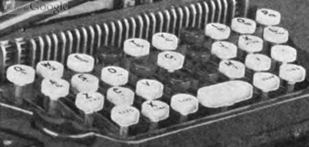
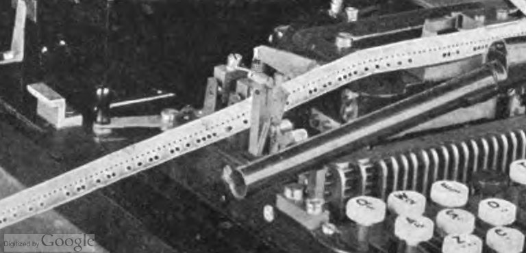


